 Overslaan naar inhoud

- Cooling accounts for 50-70% of total injection molding cycle time; optimizing it is the fastest way to reduce cost.
- The six main cooling channel types are: straight-line, baffle, bubbler, spiral, conformal, and thermal pin.
- Water cooling at 10-25 degrees C is the industry standard for most thermoplastics; oil cooling is used above 80 degrees C.
- Conformal cooling channels reduce cycle time by 20-35% compared to conventional straight channels.
- Channel diameter, pitch, and distance from cavity wall directly determine cooling uniformity and warp risk.
- In our factory, we use mold flow analysis on every new mold to verify temperature uniformity before cutting steel.
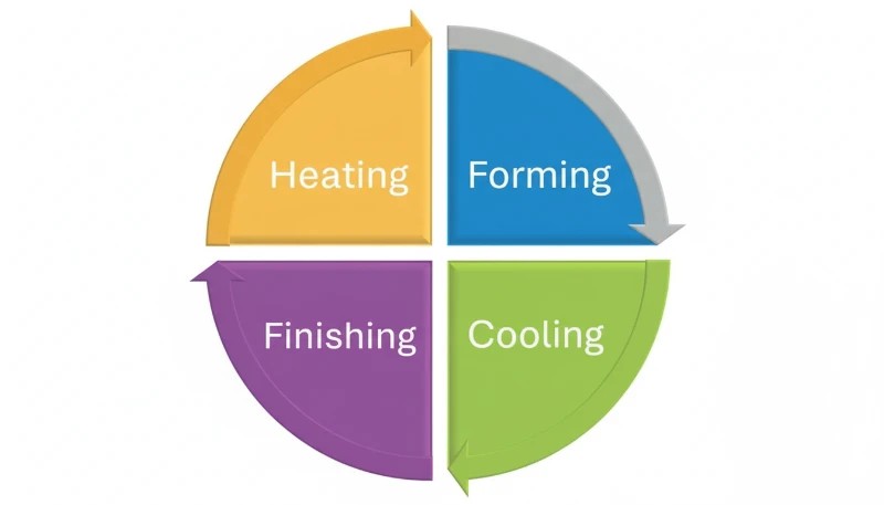
What Is an Injection Mold Cooling System?
An injection mold cooling system is a network of channels, passages, and temperature-control devices machined into the mold that remove heat from molten plastic after injection, reducing cyclustijd1 by 50-70% and ensuring dimensional accuracy. Without a properly designed cooling system, parts warp, sink marks appear, and production throughput collapses. The cooling system is not an afterthought — it determines whether your mold is profitable or a liability.
Cooling works by circulating a temperature-controlled medium — most commonly water at 10-25 degrees C — through channels drilled or printed into the mold plates surrounding the cavity. Heat from the molten plastic (injected at 180-320 degrees C depending on material) transfers into the coolant, which carries it away to an external chiller or cooling tower. The part reaches ejection temperature (typically 40-80 degrees C below the material glass transition temperature) and is removed.
In our factory in China, we run 47 injection molding machines across 3 workshops. Every mold we build receives a dedicated cooling circuit layout during DFM2 review, and we use analyse van de matrijsstroming3 to simulate temperature distribution before any steel is machined. This discipline is why our first-pass approval rate exceeds 92%.
Why Cooling System Design Matters: The Numbers
Cooling phase accounts for 50-70% of total cycle time in standard thermoplastic injection molding. A 10-second reduction in cooling time on a 30-second cycle translates to a 33% increase in throughput — producing hundreds of thousands more parts per year on the same machine with zero capital investment. That is the single highest-ROI optimization available in injection molding.
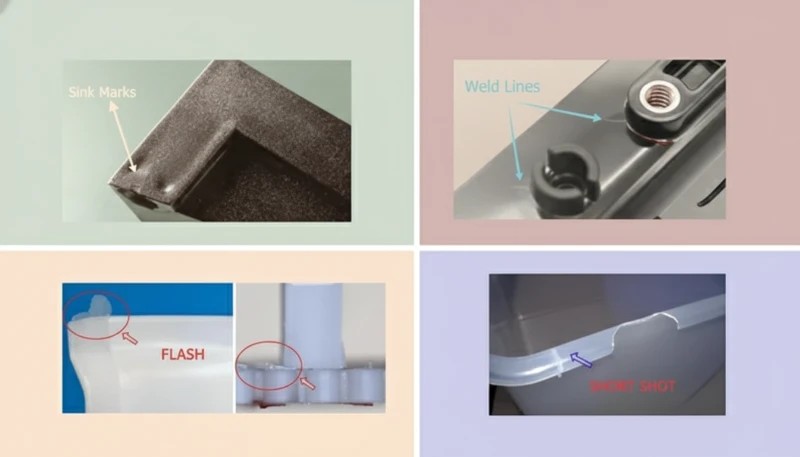
Poor cooling design creates five interconnected problems: warping and dimensional deviation from uneven temperature gradients above 5 degrees C across the cavity surface; sink marks from insufficient cooling time causing premature ejection; internal residual stress from rapid or uneven solidification; surface defects including gloss variation and blush; and extended cycle times from conservative cooling settings to compensate for poor channel placement.
All five problems cost money — either through scrap, rework, slow cycles, or failed customer inspections. In our experience reviewing hundreds of mold projects, poor cooling design is the most common root cause of first-article failures. Customers often attribute failures to material or machine settings when the actual cause is a cooling circuit that was never properly designed.
| Parameter | Poor Cooling | Optimized Cooling | Improvement |
|---|---|---|---|
| Cyclustijd | 35 sec | 22 sec | -37% |
| Temperature uniformity | >10°C delta | <3°C delta | 3x better |
| Warp (typical ABS part) | 0.8 mm | 0.15 mm | 81% reduction |
| Sink mark depth | 0.3 mm | <0.05 mm | 6x better |
| Annual throughput (1 cavity) | 825,000 shots | 1,310,000 shots | +59% |
These figures come from our engineering team’s internal benchmarking data across 200+ mold projects. The exact numbers vary by material, wall thickness, and part geometry — but the directional impact is consistent: every second of cooling time saved translates directly to cost reduction and capacity increase.
6 Types of Injection Mold Cooling Systems
Injection molds use six primary cooling channel configurations, each suited to different part geometries, precision requirements, and budget constraints. Understanding when to use each type is foundational to mold design.
1. Straight-Line Cooling Channels
Straight-line (or drilled) cooling channels are the standard for flat or simple-geometry parts, created by drilling 6-14 mm diameter holes through mold plates in a grid or parallel pattern. Channel-to-cavity distance is typically 15-25 mm for P20 steel molds, with 1.5 times channel diameter as minimum wall thickness to the cavity surface. Coolant flow rate targets turbulent flow (Reynolds number above 10,000), which transfers heat 3-5 times more efficiently than laminar flow.
Straight channels are the most cost-effective option — drilling costs $50-200 per circuit versus $500-5,000 for conformal channels — and are fully appropriate for flat lids, panels, housings with uniform wall thickness, and commodity parts. Their limitation is geometric: they cannot follow curved or complex cavity surfaces, leaving hot spots in corners and ribs where the channel is necessarily further from the cavity wall.
2. Baffle Cooling
Baffles are thin metal plates inserted into drilled channels that force coolant to flow down one side and back up the other, converting a single straight hole into a U-shaped flow path. They are used in narrow cores, pins, and areas where two parallel channels cannot be drilled side by side. A typical baffle doubles the cooling surface area in a restricted zone without requiring additional channel ports.
Baffle effectiveness depends on plate clearance (0.05-0.15 mm on each side) and coolant flow velocity. We typically specify baffles for any core diameter between 16 and 40 mm. Below 16 mm, thermal pins or bubblers are more effective; above 40 mm, spiral channels become the preferred option. The combination of baffle geometry and proper flow rate is what makes the difference between adequate and excellent core cooling.
3. Bubbler Cooling
Bubblers (also called fountain cooling) use a small-diameter inner tube inserted into a blind hole: coolant flows down the inner tube and returns up the annular space between the tube and hole wall. This creates a spray effect at the tip of the core — the hottest zone — achieving very high local heat transfer coefficients. Bubblers are standard for cores under 16 mm in diameter and deep pin features with aspect ratios above 4:1.
In our shop, we use bubblers on every core pin above 25 mm height, regardless of diameter. The additional machining cost of $30-80 per bubbler port is consistently recovered in cycle time reduction at the mold trial. For cores that are too small for bubblers, beryllium copper inserts provide passive heat conduction to nearby water channels.
4. Spiral (Helix) Cooling Channels
Spiral cooling channels wrap a helical path around cylindrical cores or circular cavities, providing uniform cooling over 360 degrees of the feature. For threaded closures, round containers, medical vials, and any rotationally symmetric part, spiral channels reduce peak-to-average temperature differential from more than 8 degrees C (with straight channels) to less than 2 degrees C.
Pitch and lead angle are tuned to the coolant flow rate — typically 4-8 mm pitch with a 45-degree helix angle for water cooling. Spiral inserts can be machined as separate components and pressed into mold cores, making them replaceable when worn or when geometry changes require a redesign.
5. Conformal Cooling Channels
conformal cooling4 channels follow the exact 3D contour of the mold cavity wall at a uniform standoff distance (typically 5-12 mm), made possible by metal additive manufacturing (DMLS or SLM). Where conventional drilled channels leave hot spots on curved surfaces and sharp corners, conformal channels maintain cavity-to-channel distance within plus or minus 1 mm across the entire surface — delivering 20-35% cycle time reduction and dramatically more uniform cooling.
The trade-off is cost and lead time: a conformal-cooled insert produced by DMLS from H13 tool steel costs $3,000-15,000 versus $500-2,000 for a conventionally machined insert. The break-even point is typically reached at 50,000-100,000 shots for high-volume parts, where cycle time savings translate to machine-hour savings that exceed the tooling premium. For medical devices, automotive trim, and consumer electronics at high volume, conformal cooling is the standard of practice.
6. Thermal Pins and Heat Pipes
Thermal pins (heat pipes) are sealed copper or beryllium copper components charged with a phase-change fluid. They passively transfer heat from hot spots — sharp corners, ribs, thin features — to a water-cooled heat sink with no active coolant flow. Heat pipe thermal conductivity reaches 10,000-100,000 W/m·K, compared to 20-50 W/m·K for P20 steel.
Thermal pins are ideal for features too small or inaccessible for active cooling channels, such as ribs under 3 mm wide or ejector pin areas. They require no plumbing connections and can be retrofitted into existing molds without major rework. In our factory, thermal pins have eliminated hot-spot sink marks on several medical device molds where ribs could not otherwise be adequately cooled.
Cooling Medium Comparison: Water, Oil, and Air
The cooling medium choice — water, oil, or air — determines heat transfer capacity, operating temperature range, maintenance requirements, and cost. Each medium fits a specific window of mold temperature requirements, and choosing the wrong medium creates quality problems that are surprisingly difficult to trace back to their root cause.
| Medium | Temp Range | Heat Transfer | Beste voor | Onderhoud |
|---|---|---|---|---|
| Water (chilled) | 10-60°C | High (3,000-10,000 W/m2K) | Most thermoplastics (PE, PP, ABS, PC) | Scale/corrosion control |
| Water (tower) | 25-35°C | Hoog | High-volume commodity parts | Algae and mineral control |
| Oil (thermal) | 60-200°C | Medium (500-2,000 W/m2K) | High-temp materials (PEI, PEEK, PPS) | Fluid replacement every 12 months |
| Lucht | Ambient | Low (50-200 W/m2K) | Thin walls, elastomers, foam parts | Minimal — filter cleaning only |
| Beryllium copper | Passive | Very high (conduction) | Thin ribs, micro features | None |
In our factory, 90% of molds run water cooling at 15-25 degrees C using a closed-loop chiller system. For engineering resins processed above 120 degrees C (PEI, PEEK, PPS, POM), we switch to temperature-controlled oil circuits that maintain mold temperature at 80-160 degrees C. Air cooling is reserved for simple silicone and thin-wall foam applications where water channel proximity would cause surface condensation.
Water chemistry management is a critical and often overlooked aspect of mold cooling. We use deionized water with pH 7-8 and a corrosion inhibitor package in all production chiller loops. Tap water causes progressive scale buildup that reduces heat transfer by 15-25% per millimeter of deposit — an invisible performance degradation that shows up as gradually increasing cycle times over 12-18 months of production.
True or False: Injection Mold Cooling Myths
“Cooling time accounts for more than half of total injection molding cycle time.”Echt
In most standard thermoplastic applications, cooling accounts for 50-70% of total cycle time. A 30-second cycle typically breaks down as: injection 3-5 sec, pack/hold 5-8 sec, cooling 15-22 sec, and ejection/mold-open 3-5 sec. Optimizing the cooling phase is the single highest-leverage action in cycle time reduction. Even a 20% improvement in cooling efficiency on a 20-second cooling window saves 4 seconds — a 13% cycle time reduction with no other changes.
“Using colder water always produces faster, better results in injection mold cooling.”Vals
Dropping coolant temperature below the dew point causes condensation on the mold surface — forming water droplets that transfer to part surfaces as cosmetic defects, accelerate mold surface rust, and cause short shots. For hygroscopic materials like nylon and ABS, mold temperature must stay above 15 degrees C to prevent moisture-related defects. The optimal coolant temperature depends on material, wall thickness, ambient humidity, and surface finish requirements — not simply the lowest achievable temperature.
These two principles — that cooling dominates cycle time and that coolant temperature must be carefully controlled — form the foundation of effective injection mold cooling system engineering. Misunderstanding either one leads to wasted machine time or cosmetic defects that fail customer inspection. The next two myths address more advanced design decisions around coolant flow dynamics and cooling technology selection. Both are frequently misapplied in practice: engineers either accept laminar flow as unavoidable or invest in conformal cooling for parts that do not justify the premium. Getting the analysis right saves both time and money.
“Turbulent coolant flow transfers heat significantly more efficiently than laminar flow.”Echt
Turbulent flow (Reynolds number above 10,000) achieves convective heat transfer coefficients of 3,000-10,000 W/m2K, compared to 500-1,500 W/m2K for laminar flow — a 3-5 times improvement in heat transfer rate. Achieving turbulence requires minimum flow velocities of 0.5-1.0 m/s for 8 mm channels. We specify flow rate requirements on every mold cooling circuit drawing and verify turbulent conditions at the mold trial using digital flow meters on each circuit port.
“Conformal cooling channels always justify their higher cost over conventional straight channels.”Vals
Conformal cooling is a premium solution justified only by high production volumes and geometrically complex parts. For flat panels, lids, and simple boxes running under 50,000 shots annually, the $10,000-30,000 DMLS tooling premium will never be recovered through cycle time savings. The break-even analysis must account for machine hourly rate, cycle time delta, annual volume, and tool life. For low-volume specialty parts, optimized straight channels deliver 90% of the benefit at 10% of the cost.
Key Design Parameters for Injection Mold Cooling
Five engineering parameters govern cooling system performance. Getting these right at the design stage prevents expensive rework after mold trials. These numbers are not arbitrary — they emerge from decades of empirical testing and thermal simulation validation.
Channel Diameter
Standard cooling channel diameters range from 6 mm (small precision molds) to 16 mm (large structural molds). The most common sizes in our shop are 8 mm and 10 mm, which balance drilling cost, flow resistance, and heat transfer surface area. Channels below 6 mm are prone to blockage from scale and corrosion and require filtered deionized water; channels above 16 mm reduce structural mold strength and increase the risk of channel-to-channel breakthrough during drilling.
Channel-to-Cavity Distance
Channel centerline-to-cavity surface distance should be 1.5-2 times the channel diameter for balanced thermal and structural performance. For an 8 mm channel in P20 steel, the target distance is 12-16 mm. Closer placement increases cooling rate but risks stress cracking and core breakthrough; greater distances reduce cooling efficiency and create hot spots between channels where the thermal gradient is not adequately controlled.
Channel Pitch (Center-to-Center Spacing)
Pitch between parallel channels affects temperature uniformity across the cavity surface. The standard recommendation is 3-5 times the channel diameter. For 10 mm channels, a pitch of 30-50 mm balances thermal uniformity against drilling cost. Wider pitch produces temperature ripple between channels; tighter pitch is structurally challenging and increases the mold plate cost.

Koelvloeistofdebiet en Reynoldsgetal
Het debiet moet een Reynoldsgetal boven 10.000 bereiken voor turbulente stroming. Voor een kanaal van 8 mm vereist dit een stroomsnelheid boven 0,7 m/s, wat overeenkomt met ongeveer 2,6 liter per minuut per circuit. Onze standaardpraktijk is om het debiet tijdens de matrijspers te verifiëren met digitale debietmeters die op elke circuitpoort zijn geïnstalleerd, en de werkelijke Reynoldsgetallen vast te leggen in het matrijsinstellingsblad voor toekomstige productiereferentie.
Inlaat- en Uitlaattemperatuurverschil
De temperatuurstijging van koelvloeistof inlaat naar uitlaat moet onder de 3-5 graden C per circuit blijven. Een groter delta duidt op onvoldoende debiet – de koelvloeistof neemt te veel warmte per passage op – en creëert een temperatuurgradiënt langs de kanaallengte, wat resulteert in ongelijkmatige koeling van het ene naar het andere uiteinde van het onderdeel. Wij streven naar een delta onder de 3 graden C als onze standaard en passen het debiet tijdens de proef aan tot dit is bereikt.
Stapsgewijs Ontwerpproces Koelsysteem
Ons technisch team volgt een gestructureerd zevenstappenproces voor elk nieuw matrijskoelsysteem, van initiële CAD-beoordeling tot validatie tijdens matrijspers. Dit proces voorkomt de meeste koelgerelateerde eerste-artikelfouten voordat ze zich voordoen.
Stap 1 is thermische belastingsberekening: schat de warmte-invoer van de geïnjecteerde kunststofmassa, materiaal-enthalpie en de gewenste cyclustijd om de vereiste koelcapaciteit in watt te bepalen. Stap 2 is selectie van kanaaltype: pas de kanaalgeometrie aan op de vorm van het onderdeel – recht voor vlakke onderdelen, spiraal voor cilindrische kenmerken, conform voor complexe 3D-geometrie, schotten en bruisstenen voor smalle kernen. Stap 3 is lay-outontwerp: positioneer kanalen op 1,5-2 keer de diameter afstand, 3-5 keer de hartafstand, met voldoende stalen bruggen tussen de kanalen.
Stap 4 is circuitplanning: ontwerp serie- en parallelschakelingen om de stroming in balans te brengen en dode zones te vermijden waar de koelvloeistofsnelheid tot nul daalt. Stap 5 is matrijssimulatie: voer thermische analyse uit in Moldex3D of Moldflow om temperatuuruniformiteit te verifiëren, hotspots te identificeren en kromtrekking te voorspellen — herhaal het ontwerp tot het temperatuurverschil tussen piek en gemiddelde onder de 5 graden C daalt. Stap 6 is DFM-beoordeling: controleer op boorinterferentie met uitstoters, geleidingspennen, lifters en schuiven. Stap 7 is matrijstestvalidatie: meet circuitdebieten, inlaat-/uitlaattemperatuurverschil en onderdeeltemperatuur bij uitstoting met infraroodthermometrie, vergelijk vervolgens met simulatievoorspellingen.
Veelvoorkomende Koelsysteemproblemen en Oplossingen
Zelfs goed ontworpen koelsystemen ontwikkelen na verloop van tijd problemen. De drie meest voorkomende problemen die we in onze fabriek tegenkomen zijn kanaalaanslag, hotspots door ontwerpblindspots en koelvloeistoflekkage in de matrijs. Elk heeft duidelijke diagnostische indicatoren en bewezen oplossingen.
| Probleem | Root Cause | Oplossing |
|---|---|---|
| Vervorming / dimensionale drift | Niet-uniforme matrijstemperatuur (>5°C verschil) | Voeg kanalen toe aan hete zones; controleer stromingsbalans |
| Aanslag/verstopte kanalen | Mineraalafzettingen door hard water | Gebruik gedemineraliseerd water; jaarlijkse zuurspoeling |
| Koelvloeistoflekkage in holte | Gebarsten kanaalwand (onvoldoende staaldikte) | Herontwerp met >10 mm wand; gebruik O-ringen bij inzetstukken |
| Verlengde cyclustijd | Onvoldoende stromingssnelheid (laminaire stroming) | Verhoog de pompdruk; verkort de leidinglengte; herformaat kanalen |
| Oppervlaktecondensatie/roest | Koelvloeistof onder dauwpunt | Verhoog koelmiddeltemperatuur; gebruik vochtbarrières |
| Hotspots op ribben/dunne wanden | Kanalen te ver van kenmerk | Voeg bruisstenen, schotten of thermische pennen toe in getroffen zones |
Aanslag is volgens onze ervaring de nummer één langetermijn koeling killer. Een 1 mm aanslaglaag op een kanaalwand vermindert warmteoverdracht ongeveer 15-25%. We verplichten driemaandelijkse koelcircuit inspecties op alle productiemallen, met chemische ontkalking elke 6-12 maanden afhankelijk van waterhardheid. Mallen die op stadswater werken vereisen frequenter onderhoud dan die op gedemineraliseerde watercircuits.
Lekkage van koelvloeistof in de matrijsholte komt minder vaak voor, maar is catastrofaal ontwrichtend wanneer het gebeurt – de productie stopt onmiddellijk en de matrijs moet gerepareerd worden. De voornaamste oorzaak is onvoldoende wanddikte tussen het koelkanaal en het holteoppervlak, meestal door een kanaal dat tijdens productie te dicht is geboord of een scheur die is voortgekomen uit een reeds bestaand oppervlaktedefect. Wij verifiëren de minimale wanddikte tijdens de DFM-beoordeling en controleren opnieuw met CMM-meting na de bewerking, vóór elke matrijspers.
Conform Koelen vs. Conventioneel Koelen: Wanneer te Kiezen
Conformele koeling is niet altijd de juiste keuze. Het beslissingskader is eenvoudig: vergelijk de meerkosten voor gereedschap met de waarde van de bespaarde cyclustijd over de geplande productiehoeveelheid. Deze analyse verkeerd uitvoeren kost geld — ofwel door te veel uit te geven aan premium gereedschap voor een onderdeel met lage volumes, of door aanzienlijke cyclustijdwinsten te laten liggen voor een onderdeel met hoge volumes.
| Factor | Kies Conventioneel | Kies Conform |
|---|---|---|
| Onderdeelgeometrie | Vlakke, uniforme wanddikte | Complex 3D, variabele wanddikte |
| Annual volume | <50,000 shots | >100.000 shots |
| Cyclus tijd doel | Geen agressieve beperking | 20%+ reductie vereist |
| Kromtrekkingstolerantie | +/-0,5 mm acceptabel | <+/-0,2 mm vereist |
| Gereedschapsbudget | Standaard budget | 20-50% premie acceptabel |
| Materiaal | PE, PP, ABS (vergevingsgezind) | PC/ABS, Nylon, technische kunststoffen (gevoelig) |
In onze fabriek adviseren we conformaal koelen voor automotive exterieurafwerking, behuizingen voor medische apparaten en consumentenelektronica-onderdelen waar cosmetische normen streng zijn, de wanddikte aanzienlijk varieert en de jaarlijkse volumes meer dan 100.000 shots bedragen. Voor verpakkingen, standaard behuizingen en prototype-gereedschappen levert geoptimaliseerd conventioneel koelen de vereiste kwaliteit tegen een fractie van de kosten. De beslissing hoort thuis in de DFM-beoordeling — niet nadat de eerste matrijspoging een cyclus tijdprobleem onthult.
De Evoluerende Kosten van Conformale Koeltechnologie
De economie van conform koelen is de afgelopen vijf jaar aanzienlijk veranderd, aangezien de kosten van DMLS-machines (Direct Metal Laser Sintering) met 40-60% zijn gedaald en de levertijden zijn verkort van 8 weken naar 2-3 weken. In 2020 werd conform koelen voornamelijk gerechtvaardigd voor automotive en medische toepassingen. Tegenwoordig raden we het steeds vaker aan voor elk onderdeel met een wanddiktevariatie boven 2:1 waar de jaarlijkse volumes meer dan 75.000 shots bedragen. De break-even-berekening komt nu vaak uit in het voordeel van conform koelen in toepassingen die slechts een paar jaar geleden nog standaard naar conventionele kanalen zouden zijn gegaan.
Een onderschat voordeel van conformaal koelen is de impact op de consistentie van het onderdeel, niet alleen op de snelheid. Wanneer de temperatuurverdeling uniform is binnen 2-3 graden Celsius, neemt de dimensionele variatie van shot tot shot aanzienlijk af — een factor die enorm belangrijk is in de productie van medische apparaten en precisie auto-onderdelen waar Cpk-eisen boven 1,67 standaard zijn. In onze fabriek verminderde het overschakelen van drie matrijzen voor medische apparaten van conventioneel naar conformaal koelen de dimensionele procesvariatie met 35-45%, waardoor een belangrijke bron van inspectie-afkeuringen op klantniveau werd geëlimineerd.

Veelgestelde Vragen Over Spuitgietmatrijs Koelsystemen
Hoe lang moet de afkoeltijd zijn bij spuitgieten?
Koeltijd hangt af van wanddikte, thermische geleidbaarheid van het materiaal, matrijstemperatuur en vereiste uitwerp temperatuur. De vuistregel is: koeltijd in seconden is ongeveer gelijk aan de wanddikte in millimeters in het kwadraat, vermenigvuldigd met een materiaalfactor van 1,5-2,5 voor amorfe kunststoffen (ABS, PC) en 2,0-4,0 voor semi-kristallijne kunststoffen (PP, PA, POM). Voor een 3 mm ABS wand, verwacht 9-13 seconden koeling; voor een 3 mm PP wand, 18-36 seconden. Ons engineeringteam berekent de vereiste koeltijd tijdens de DFM-beoordeling met thermische simulatietools — niet alleen met vuistregels — omdat variatie in wanddikte binnen één onderdeel zeer verschillende koelduur voor verschillende secties kan vereisen.
Wat veroorzaakt vervorming in spuitgietonderdelen?
Vervorming wordt veroorzaakt door differentiële krimp over het onderdeel, wat het gevolg is van ongelijke koeling. Wanneer één oppervlak sneller afkoelt dan het tegenoverliggende oppervlak, krimpt het meer en buigt het onderdeel naar de koelere kant. Temperatuurgradiënten van meer dan 5-8 graden Celsius tussen holte- en kernzijde zijn de meest voorkomende hoofdoorzaak. Andere bijdragende factoren zijn asymmetrische wanddikte, onvoldoende pakdruk, locatie van de ingang, en vezeloriëntatie-effecten in glasgevulde materialen. Het belangrijkste herstel is het balanceren van de koelcircuitlay-out — bevestigd via matrijsstromingsanalyse met thermische simulatie voordat er staal wordt gesneden. Pogingen om vervorming alleen via aanpassingen van de pakdruk te corrigeren slagen zelden als de hoofdoorzaak in het koelontwerp ligt.
Hoe bereken je de diameter en afstand van koelkanalen?
Standaard richtlijnen voor het ontwerp van koelkanalen: kanaaldiameter moet 6-16 mm zijn (meestal 8-10 mm voor algemeen gereedschap); afstand van kanaallas tot holteoppervlak moet 1,5-2,0 keer de kanaaldiameter zijn; kanaalsteek (afstand hart-op-hart) moet 3-5 keer de kanaaldiameter zijn. Voor een kanaal met een diameter van 10 mm is de streefafstand tot de holte 15-20 mm, met een steek van 30-50 mm. Deze initiële parameters worden gevalideerd via thermische simulatie met Moldex3D of Moldflow om te bevestigen dat de piek-tot-gemiddelde temperatuurvariatie over het hele holteoppervlak onder volledige productieomstandigheden onder de 5 graden Celsius blijft, voordat er staal wordt bewerkt.
Wat is het verschil tussen serie- en parallelle koelcircuits?
In een serieschakeling stroomt koelvloeistof door alle kanalen in een enkele ononderbroken weg voordat deze de matrijs verlaat. Dit is eenvoudig aan te sluiten, maar zorgt ervoor dat de koelvloeistoftemperatuur aanzienlijk stijgt van inlaat naar uitlaat, wat een temperatuurgradiënt creëert die zorgt voor ongelijkmatige koeling over de lengte van het onderdeel. In een parallelschakeling wordt de koelvloeistofstroom gelijktijdig over meerdere kanalen verdeeld en weer samengevoegd bij de uitlaatspruitstuk, waardoor een gelijkmatigere temperatuurverdeling in de gehele matrijs behouden blijft. De meeste productiematrijzen gebruiken een combinatiebenadering: korte serieschakelingen voor individuele zones, gebalanceerd via parallelle spruitstukken over de gehele matrijs om een uniforme inlaattemperatuur van de koelvloeistof in elke zone te bereiken.
Waarom heeft mijn mal hete plekken ondanks een koelsysteem?
Hotspots ontstaan wanneer koelkanalen te ver van de holtevlakte liggen, wanneer de stroomsnelheid onvoldoende is en laminaire stromingscondities creëert, wanneer kalkaanslag de kanalen isoleert van effectieve warmteoverdracht, of wanneer bepaalde kenmerken — dunne ribben, scherpe hoeken, kleine kernen — niet bereikt kunnen worden door conventionele kanalen. Oplossingen omvatten het toevoegen van bubblers of thermische pinnen aan ontoegankelijke kenmerken, het verifiëren van turbulente stromingscondities tijdens proeven met digitale debietmeters, het jaarlijks uitvoeren van zuurontkalking op alle circuits, en het upgraden naar conformale koelinzetstukken in chronisch hete gebieden die zijn geïdentificeerd via infrarood temperatuurmeting van het onderdeel na uitwerping.
-
cycle time: Cyclustijd is de totale duur van één complete spuitgietcyclus, gemeten in seconden, en omvat de fasen van injectie, koeling en uitwerping. ↩
-
DFM: DFM (Design for Manufacturability) is een ingenieursmethodologie die het productontwerp optimaliseert om de efficiëntie en kosteneffectiviteit van het productieproces te verbeteren. ↩
-
mold flow analysis: Matrijsstromingsanalyse is een computersimulatieproces dat voorspelt hoe gesmolten kunststof een matrijsholte vult, inclusief koelgedrag, vervorming en krimp. ↩
-
conformal cooling: Conformaal koelen verwijst naar een matrijs koeltechniek waarbij kanalen zijn ontworpen om de contour van de matrijsholte te volgen, waardoor uniforme warmteafvoer over complexe onderdeelgeometrieën mogelijk is. ↩


