 コンテンツへスキップ

- Cooling accounts for 50-70% of total injection molding cycle time; optimizing it is the fastest way to reduce cost.
- The six main cooling channel types are: straight-line, baffle, bubbler, spiral, conformal, and thermal pin.
- Water cooling at 10-25 degrees C is the industry standard for most thermoplastics; oil cooling is used above 80 degrees C.
- Conformal cooling channels reduce cycle time by 20-35% compared to conventional straight channels.
- Channel diameter, pitch, and distance from cavity wall directly determine cooling uniformity and warp risk.
- In our factory, we use mold flow analysis on every new mold to verify temperature uniformity before cutting steel.
What Is an Injection Mold Cooling System?
An injection mold cooling system is a network of channels, passages, and temperature-control devices machined into the mold that remove heat from molten plastic after injection, reducing サイクルタイム1 by 50-70% and ensuring dimensional accuracy. Without a properly designed cooling system, parts warp, sink marks appear, and production throughput collapses. The cooling system is not an afterthought — it determines whether your mold is profitable or a liability.
Cooling works by circulating a temperature-controlled medium — most commonly water at 10-25 degrees C — through channels drilled or printed into the mold plates surrounding the cavity. Heat from the molten plastic (injected at 180-320 degrees C depending on material) transfers into the coolant, which carries it away to an external chiller or cooling tower. The part reaches ejection temperature (typically 40-80 degrees C below the material glass transition temperature) and is removed.
In our factory in China, we run 47 injection molding machines across 3 workshops. Every mold we build receives a dedicated cooling circuit layout during DFM2 review, and we use 金型流動解析3 to simulate temperature distribution before any steel is machined. This discipline is why our first-pass approval rate exceeds 92%.
Why Cooling System Design Matters: The Numbers
Cooling phase accounts for 50-70% of total cycle time in standard thermoplastic injection molding. A 10-second reduction in cooling time on a 30-second cycle translates to a 33% increase in throughput — producing hundreds of thousands more parts per year on the same machine with zero capital investment. That is the single highest-ROI optimization available in injection molding.
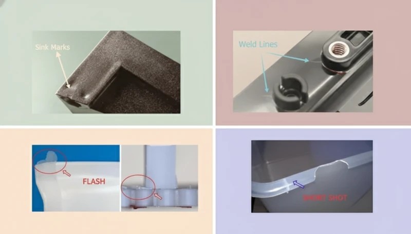
Poor cooling design creates five interconnected problems: warping and dimensional deviation from uneven temperature gradients above 5 degrees C across the cavity surface; sink marks from insufficient cooling time causing premature ejection; internal residual stress from rapid or uneven solidification; surface defects including gloss variation and blush; and extended cycle times from conservative cooling settings to compensate for poor channel placement.
All five problems cost money — either through scrap, rework, slow cycles, or failed customer inspections. In our experience reviewing hundreds of mold projects, poor cooling design is the most common root cause of first-article failures. Customers often attribute failures to material or machine settings when the actual cause is a cooling circuit that was never properly designed.
| パラメータ | Poor Cooling | Optimized Cooling | Improvement |
|---|---|---|---|
| サイクルタイム | 35 sec | 22秒 | -37% |
| Temperature uniformity | >10°C delta | <3°C delta | 3x better |
| Warp (typical ABS part) | 0.8 mm | 0.15 mm | 81% reduction |
| Sink mark depth | 0.3 mm | <0.05 mm | 6x better |
| Annual throughput (1 cavity) | 825,000 shots | 1,310,000 shots | +59% |
These figures come from our engineering team’s internal benchmarking data across 200+ mold projects. The exact numbers vary by material, wall thickness, and part geometry — but the directional impact is consistent: every second of cooling time saved translates directly to cost reduction and capacity increase.
6 Types of Injection Mold Cooling Systems
Injection molds use six primary cooling channel configurations, each suited to different part geometries, precision requirements, and budget constraints. Understanding when to use each type is foundational to mold design.
1. Straight-Line Cooling Channels
Straight-line (or drilled) cooling channels are the standard for flat or simple-geometry parts, created by drilling 6-14 mm diameter holes through mold plates in a grid or parallel pattern. Channel-to-cavity distance is typically 15-25 mm for P20 steel molds, with 1.5 times channel diameter as minimum wall thickness to the cavity surface. Coolant flow rate targets turbulent flow (Reynolds number above 10,000), which transfers heat 3-5 times more efficiently than laminar flow.
Straight channels are the most cost-effective option — drilling costs $50-200 per circuit versus $500-5,000 for conformal channels — and are fully appropriate for flat lids, panels, housings with uniform wall thickness, and commodity parts. Their limitation is geometric: they cannot follow curved or complex cavity surfaces, leaving hot spots in corners and ribs where the channel is necessarily further from the cavity wall.
2. Baffle Cooling
Baffles are thin metal plates inserted into drilled channels that force coolant to flow down one side and back up the other, converting a single straight hole into a U-shaped flow path. They are used in narrow cores, pins, and areas where two parallel channels cannot be drilled side by side. A typical baffle doubles the cooling surface area in a restricted zone without requiring additional channel ports.
Baffle effectiveness depends on plate clearance (0.05-0.15 mm on each side) and coolant flow velocity. We typically specify baffles for any core diameter between 16 and 40 mm. Below 16 mm, thermal pins or bubblers are more effective; above 40 mm, spiral channels become the preferred option. The combination of baffle geometry and proper flow rate is what makes the difference between adequate and excellent core cooling.
3. バブラー冷却
バブラー(噴流冷却とも呼ばれる)は、盲穴に挿入された小径の内管を使用します:冷却液は内管を流れ下り、管と穴壁の間の環状空間を上って戻ります。これによりコアの先端 — 最も高温な領域 — で噴霧効果が生まれ、非常に高い局所熱伝達係数を達成します。バブラーは直径16 mm未満のコアおよびアスペクト比4:1以上の深いピン形状に標準的に用いられます。
当社では、直径に関わらず高さ25 mmを超える全てのコアピンにバブラーを使用しています。バブラーポートあたり$30-80の追加加工コストは、金型試作時のサイクルタイム短縮で一貫して回収されています。バブラーが小さすぎるコアには、ベリリウム銅インサートが近接する水冷チャネルへの受動的な熱伝導を提供します。
4. 螺旋(ヘリックス)冷却チャネル
螺旋冷却チャネルは円筒形コアまたは円形キャビティの周りにらせん状の経路を巻き付け、特徴の360度にわたって均一な冷却を提供します。ねじ込み式クロージャー、丸型容器、医療用バイアル、および回転対称部品の場合、螺旋チャネルはピークから平均までの温度差を8℃以上(直線チャネルの場合)から2℃未満に低減します。
ピッチとリード角は冷却液の流量に合わせて調整されます — 一般的に水冷では4-8 mmピッチで45度のヘリックス角が用いられます。螺旋インサートは別部品として加工され、金型コアに圧入されるため、摩耗時や形状変更による再設計が必要な場合に交換可能です。
5. コンフォーマル冷却チャネル
conformal cooling4 チャネルは、金属積層造形(DMLSまたはSLM)によって可能となった均一な間隔(通常5〜12 mm)で、金型キャビティ壁の正確な3D輪郭に沿っています。従来のドリル加工されたチャネルが曲面や鋭角にホットスポットを残すのに対し、コンフォーマルチャネルは全体の表面でキャビティからチャネルまでの距離をプラスマイナス1 mm以内に維持し、20〜35%のサイクル時間短縮と劇的に均一な冷却を実現します。
トレードオフはコストとリードタイムです。H13工具鋼を用いたDMLSで製造されたコンフォーマル冷却インサートのコストは$3,000-15,000であるのに対し、従来加工のインサートは$500-2,000です。損益分岐点は通常、大量生産部品で50,000-100,000ショットに達し、サイクルタイム短縮による機械稼働時間の節約が工具プレミアムを上回ります。医療機器、自動車トリム、大量生産の民生電子機器では、コンフォーマル冷却が標準的な実践です。
6. サーモピンおよびヒートパイプ
サーモピン(ヒートパイプ)は、相変化流体を封入した密封銅またはベリリウム銅部品です。これらはアクティブな冷却液流を必要とせず、鋭角なコーナー、リブ、薄肉部などのホットスポットから水冷ヒートシンクへ受動的に熱を伝達します。ヒートパイプの熱伝導率は10,000-100,000 W/m·Kに達し、P20鋼の20-50 W/m·Kと比較されます。
サーモピンは、3mm幅未満のリブやエジェクターピン領域など、アクティブ冷却チャネルには小さすぎる、またはアクセスできない形状に理想的です。配管接続を必要とせず、大規模な改修なしで既存金型に後付けできます。当社工場では、リブを適切に冷却できないいくつかの医療機器金型において、サーモピンによりホットスポットのシンクマークが解消されました。
Cooling Medium Comparison: Water, Oil, and Air
冷却媒体の選択 — 水、油、または空気 — は熱伝達能力、作動温度範囲、メンテナンス要件、およびコストを決定します。各媒体は特定の金型温度要件の範囲に適合し、誤った媒体を選択すると、根本原因を突き止めることが驚くほど困難な品質問題を引き起こします。
| ミディアム | Temp Range | 熱伝導 | 最適 | メンテナンス |
|---|---|---|---|---|
| 水(冷却水) | 10-60°C | 高い(3,000-10,000 W/m2K) | ほとんどの熱可塑性プラスチック(PE、PP、ABS、PC) | スケール/腐食制御 |
| 水(冷却塔) | 25-35°C | 高い | High-volume commodity parts | 藻類およびミネラル制御 |
| 油(熱媒体) | 60-200°C | 中程度(500-2,000 W/m2K) | 高温材料(PEI、PEEK、PPS) | 12か月ごとの流体交換 |
| 空気 | アンビエント | 低い(50-200 W/m2K) | 薄肉、エラストマー、フォーム部品 | 最小限(フィルター清掃のみ) |
| ベリリウム銅 | 受動的 | 非常に高い(伝導) | 薄肉リブ、微細形状 | None |
当社工場では、90%の金型が密閉ループ冷却装置システムを使用して15-25°Cで水冷運転されています。120°C以上で加工されるエンジニアリング樹脂(PEI、PEEK、PPS、POM)については、金型温度を80-160°Cに維持する温度制御油回路に切り替えます。空冷は、水冷チャネルが近接すると表面結露を引き起こす単純なシリコーンおよび薄肉発泡成形用途に限定されます。
水質管理は金型冷却の重要でありながら見過ごされがちな側面です。当社では全ての生産用冷却装置ループでpH 7-8の脱イオン水と腐食抑制剤パッケージを使用しています。水道水は徐々にスケールを蓄積し、堆積物1 mmあたり15-25%の熱伝達低下を引き起こします — これは12-18ヶ月の生産期間中にサイクルタイムが徐々に増加するという目に見えない性能劣化として現れます。
True or False: Injection Mold Cooling Myths
「冷却時間は射出成形サイクルタイムの半分以上を占めます。」真
ほとんどの標準的な熱可塑性プラスチックの成形では、冷却は総サイクル時間の50-70%を占めます。30秒のサイクルは通常、射出3-5秒、保圧5-8秒、冷却15-22秒、頂出/開型3-5秒に分解されます。冷却段階の最適化は、サイクルタイム短縮において最も効果的なアクションです。20秒の冷却ウィンドウで冷却効率を20%改善するだけで4秒節約でき、他の変更を伴わずにサイクルタイムを13%短縮できます。
「より冷たい水を使用すると、射出成形金型冷却において常に速く、優れた結果が得られます。」偽
冷却液温度を露点以下に下げると、金型表面に結露が発生します。これは水滴となって製品表面に転写され、外観不良を引き起こし、金型表面の錆を促進し、ショートショットを引き起こします。ナイロンやABSなどの吸湿性材料では、水分関連の欠陥を防ぐため、金型温度は摂氏15度以上を維持する必要があります。最適な冷却液温度は、材料、肉厚、周囲湿度、表面仕様要件に依存し、単に達成可能な最低温度ではありません。
冷却がサイクルタイムを支配し、冷却液温度は慎重に制御されなければならないというこれら二つの原則は、効果的な射出成形金型冷却システム設計の基礎を形成します。いずれかを誤解すると、機械時間の無駄や顧客検査で不合格となる外観不良を招きます。次の二つの誤解は、冷却液流動力学と冷却技術選択に関するより高度な設計判断に対処します。どちらも実践で頻繁に誤用されています:技術者は層流を不可避として受け入れるか、プレミアムに見合わない部品にコンフォーマル冷却を投資します。正しい分析を行うことで時間とコストの両方を節約できます。
「乱流冷却液流は、層流と比較して熱をはるかに効率的に伝達します。」真
乱流(レイノルズ数10,000以上)は、3,000-10,000 W/m2Kの対流熱伝達係数を達成します。これは層流の500-1,500 W/m2Kと比較して熱伝達率が3~5倍向上します。乱流を達成するには、8mmチャネルで最低0.5-1.0 m/sの流速が必要です。当社は全ての金型冷却回路図に流量要件を明記し、各回路ポートにデジタル流量計を使用して試運転時に乱流条件を検証します。
「コンフォーマル冷却チャネルは、従来の直線チャネルよりも高コストであることを常に正当化します。」偽
コンフォーマル冷却は、高生産量と幾何学的に複雑な部品によってのみ正当化されるプレミアムソリューションです。年間50,000ショット未満で稼働するフラットパネル、蓋、およびシンプルなボックスの場合、1万から3万ドルのDMLS金型プレミアムは、サイクル時間の短縮によって回収されることはありません。損益分岐点分析では、機械の時間当たり料金、サイクル時間差、年間生産量、および金型寿命を考慮する必要があります。低量産の特殊部品の場合、最適化された直線チャネルは、コストの10%で利益の90%をもたらします。
Key Design Parameters for Injection Mold Cooling
冷却システム性能を決定する5つの設計パラメータがあります。設計段階でこれらを適切に設定することで、試運転後の高額な再作業を防ぎます。これらの数値は任意ではなく、数十年にわたる経験的試験と熱シミュレーションによる検証から導き出されたものです。
Channel Diameter
標準的な冷却チャネルの直径は、6mm(小型精密金型)から16mm(大型構造金型)の範囲です。当社で最も一般的なサイズは8mmと10mmで、これは穴あけコスト、流動抵抗、熱伝達面積のバランスを考慮したものです。6mm未満のチャネルはスケールや腐食による閉塞のリスクが高く、ろ過された脱イオン水が必要です。16mmを超えるチャネルは金型構造強度を低下させ、穴あけ中のチャネル間貫通のリスクを高めます。
チャネル-キャビティ間距離
チャネル中心線からキャビティ表面までの距離は、熱的・構造的性能のバランスを保つために、チャネル径の1.5~2倍とする必要があります。P20鋼における8mmチャネルの場合、目標距離は12~16mmです。近接配置は冷却速度を向上させますが、応力割れやコア突破のリスクがあります;距離を広げると冷却効率が低下し、チャネル間に熱勾配が十分に制御されないホットスポットが生じます。
チャネルピッチ(中心間隔)
平行チャネル間のピッチは、キャビティ表面全体の温度均一性に影響します。標準的な推奨値はチャネル径の3~5倍です。10mmチャネルの場合、30~50mmのピッチが熱均一性とドリリングコストのバランスを取ります。広いピッチはチャネル間に温度リップルを生じさせ、狭いピッチは構造的に困難で金型プレートのコストを増加させます。

冷却液流量とレイノルズ数
乱流を実現するにはレイノルズ数が10,000以上になる流量が必要です。8 mmチャネルの場合、流速0.7 m/s以上が必要で、これは回路あたり約2.6リットル/分に相当します。当社の標準的な実践では、各回路ポートに設置されたデジタル流量計を使用して金型試運転時に流量を確認し、実際のレイノルズ数を金型設定シートに記録して将来の生産に備えます。
入口・出口温度差
冷却液の入口から出口までの温度上昇は、回路ごとに3-5℃以下に抑えるべきです。大きなデルタは流量不足を示し、冷却液が1回の通過で吸収する熱量が多すぎることを意味します。これによりチャネル長に沿った温度勾配が生じ、部品の一端から他端まで不均一な冷却が発生します。当社ではデルタを3℃未満を標準目標とし、試作時に流量を調整してこれを達成します。
Step-by-Step Cooling System Design Process
当社のエンジニアリングチームは、あらゆる新しい金型冷却システムに対して、初期のCADレビューから金型試作検証まで、構造化された7段階のプロセスを採用しています。このプロセスにより、冷却関連の初回不良の大半を未然に防ぎます。
ステップ1は熱負荷計算です:射出プラスチック質量、材料エンタルピー、およびサイクル時間目標からの熱入力を推定し、必要な冷却能力をワットで定義します。ステップ2はチャネルタイプの選択です:部品形状に合わせてチャネル形状を選択します — 平坦な部品には直線、円筒形状にはスパイラル、複雑な3D形状にはコンフォーマル、狭いコアにはバッフルとバブラーを使用します。ステップ3はレイアウト設計です:チャネルを直径の1.5〜2倍の距離、ピッチの3〜5倍で配置し、チャネル間に十分な鋼材ブリッジを確保します。
ステップ4は回路計画です:直列および並列回路を設計し、流動をバランスさせ、冷却液流速がゼロになるデッドレッグゾーンを回避します。ステップ5は金型流動シミュレーションです:Moldex3DまたはMoldflowで熱解析を実行し、温度均一性を確認し、ホットスポットを特定し、反りを予測します—レイアウトを繰り返し、ピーク対平均温度差が5°C未満になるまで調整します。ステップ6はDFMレビューです:エジェクタピン、リーダーピン、リフター、スライドとのドリリング干渉をチェックします。ステップ7は金型試作検証です:赤外線温度計を用いて回路流量、入口/出口温度差、および離型時の部品温度を測定し、シミュレーション予測と比較します。
Common Cooling System Problems and Solutions
設計が優れた冷却システムでも時間の経過とともに問題が発生します。当社の工場で最も頻繁に遭遇する3つの問題は、チャネルのスケール堆積、設計上の死角によるホットスポット、および金型キャビティへの冷却液漏れです。それぞれには明確な診断指標と実証済みの対策があります。
| 問題 | Root Cause | ソリューション |
|---|---|---|
| 反り/寸法ドリフト | 不均一なキャビティ温度(>5°C差) | 高温ゾーンにチャネルを追加する;流動バランスを確認する |
| スケール/閉塞したチャネル | 硬水によるミネラル堆積物 | 脱イオン水を使用する;年次酸洗浄を実施する |
| キャビティへの冷却液漏れ | クラックが入った冷却チャネル壁(鋼材厚さ不足) | 壁厚を10mm以上に再設計し、インサート部にOリングを使用する |
| サイクル時間の延長 | 流量不足(層流) | ポンプ圧力を上げる;回路長を短縮する;チャネルサイズを変更する |
| 表面結露/錆 | 露点以下の冷却液 | 冷却液温度を上げる;防湿バリアを使用する |
| リブ/薄肉部のホットスポット | 特徴部からチャネルが遠すぎる | 影響を受けたゾーンにバブラー、バッフル、またはサーモピンを追加する |
経験上、スケールの堆積は冷却性能を長期的に低下させる最大の要因です。チャネル壁に1mmのスケール層が付着すると、熱伝達率は約15-25%低下します。当社では全ての量産金型に対し、四半期ごとの冷却回路点検を義務付け、水質硬度に応じて6-12ヶ月ごとに酸洗浄によるスケール除去を行います。水道水を使用する金型は、脱イオン水ループを使用する金型よりも頻繁なメンテナンスが必要です。
金型キャビティへの冷却液漏れは比較的稀ですが、発生すると壊滅的な混乱を引き起こします。生産は直ちに停止し、金型の修理が必要となります。主な原因は、冷却チャネルとキャビティ表面間の肉厚不足で、通常は加工時にチャネルを近すぎる位置に穴あけしたか、既存の表面欠陥から亀裂が進展したことによります。当社ではDFMレビュー時に最小肉厚を確認し、加工後、金型試作前にCMM測定で再確認します。
Conformal Cooling vs. Conventional Cooling: When to Choose
コンフォーマル冷却は常に正解ではありません。判断基準は明確です:計画生産数量に対するサイクルタイム短縮の価値と、金型コストのプレミアムを比較します。この分析を誤ると、どちらの方向でもコストがかかります—低量産部品に対してプレミアム金型に過剰投資するか、高量産部品で大きなサイクルタイム短縮の機会を逃すことになります。
| ファクター | 従来型を選択 | コンフォーマルを選択 |
|---|---|---|
| 部品形状 | 平坦で均一な肉厚 | 複雑な3D形状、可変肉厚 |
| 年間生産量 | <50,000 shots | >100,000ショット |
| サイクルタイム目標 | 積極的な制約なし | 20%+ 削減が必要 |
| 反り許容値 | +/-0.5 mm 許容可能 | <+/-0.2 mm 必要 |
| 金型予算 | 標準予算 | 20-50%プレミアム許容 |
| 素材 | PE、PP、ABS(許容性が高い) | PC/ABS、ナイロン、エンジニアリング樹脂(敏感) |
当社の工場では、外観基準が厳格で、肉厚が大きく変動し、年間生産量が100,000ショットを超える自動車外装部品、医療機器筐体、および民生用電子機器部品に対して、コンフォーマル冷却を推奨しています。包装材、汎用品筐体、および試作金型では、最適化された従来の冷却方式が、コストを大幅に抑えながら必要な品質を達成します。この判断はDFMレビューで行われるべきであり、最初の金型試作でサイクルタイムの問題が明らかになった後ではありません。
コンフォーマル冷却技術の進化するコスト
コンフォーマル冷却の経済性は、過去5年間で大きく変化しました。DMLS(直接金属レーザー焼結)機械のコストが40-60%低下し、納期が8週間から2-3週間に圧縮されたためです。2020年には、コンフォーマル冷却は主に自動車および医療用途で正当化されました。今日では、肉厚変動が2:1以上で年間生産量が75,000ショットを超える部品に対して、ますます推奨されています。現在、ブレークイーブンの計算は、わずか数年前まで従来のチャネルが標準であった用途でも、頻繁にコンフォーマル冷却を支持します。
コンフォーマル冷却の過小評価されている利点の一つは、速度だけでなく部品の一貫性への影響です。温度分布が2-3度C以内で均一になると、ショット間の寸法変動が大幅に減少します。これは、Cpk要件が1.67以上が標準である医療機器製造や精密自動車部品において非常に重要な要素です。当社の工場では、3つの医療機器金型を従来式からコンフォーマル冷却に切り替えたことで、寸法プロセス変動が35-45%減少し、顧客レベルでの検査不良の重要な原因を排除しました。

Frequently Asked Questions About Injection Mold Cooling Systems
射出成形における冷却時間はどのくらいにすべきですか?
冷却時間は肉厚、材料の熱伝導率、金型温度、および必要な離型温度に依存します。経験則では:冷却時間(秒)は肉厚(mm)の平方にほぼ等しく、非晶性樹脂(ABS、PC)では材料係数1.5-2.5を乗じ、半結晶性樹脂(PP、PA、POM)では2.0-4.0を乗じます。3 mmのABS肉厚の場合、冷却時間は9-13秒;3 mmのPP肉厚の場合、18-36秒と予測されます。当社のエンジニアリングチームは、DFMレビュー時に熱シミュレーションツールを使用して必要な冷却時間を計算します — 経験則だけではありません — 単一部品内の肉厚変動により、異なる部分で非常に異なる冷却時間が必要になる場合があります。
射出成形部品の反りは何が原因で発生しますか?
ワーピングは、不均一な冷却によって生じる部品全体の収縮差によって引き起こされます。一方の表面が反対側の表面よりも速く冷却されると、より多く収縮し、部品を冷却側に向かって曲げます。キャビティ側とコア側の温度勾配が5-8度Cを超えることが最も一般的な根本原因です。その他の要因には、非対称な肉厚、不十分な保圧圧力、ゲート位置、ガラス充填材における繊維配向効果などがあります。主な対策は、冷却回路レイアウトのバランス調整です。これは、鋼材を切削する前に熱シミュレーションを用いた金型流動解析によって確認されます。根本原因が冷却設計にある場合、保圧圧力調整のみでワーピングを修正しようとしても、ほとんど成功しません。
冷却チャネルの直径と間隔はどのように計算しますか?
冷却チャネル設計の標準的な業界ガイドライン:チャネル径は6-16 mm(一般的な金型では最も一般的に8-10 mm);チャネル中心線からキャビティ表面までの距離はチャネル径の1.5-2.0倍;チャネルピッチ(中心間間隔)はチャネル径の3-5倍。10 mm径のチャネルの場合、キャビティからの距離目標は15-20 mm、ピッチは30-50 mm。これらの初期パラメータは、Moldex3DまたはMoldflowを用いた熱シミュレーションで検証され、鋼材が加工される前に、完全な生産条件下でキャビティ表面全体のピークから平均温度変動が5度C以下であることを確認します。
シリーズ冷却回路とパラレル冷却回路の違いは何ですか?
直列回路では、冷却液はすべてのチャネルを通って単一の連続した経路を流れ、金型から排出されます。これは配管が簡単ですが、冷却液の温度が入口から出口で大幅に上昇し、温度勾配を生み出し、部品長さ全体で不均一な冷却を引き起こします。並列回路では、冷却液の流れは複数のチャネルに同時に分割され、出口マニホールドで再結合され、金型全体でより均一な温度分布を維持します。ほとんどの生産金型では、組み合わせアプローチを使用します:個々のゾーンに対して短い直列回路を用い、金型全体の並列マニホールドを通じてバランスを取ることで、すべてのゾーンで均一な冷却液入口温度を達成します。
なぜ冷却システムがあるのに、私の金型にホットスポットが発生するのですか?
ホットスポットは、冷却チャネルがキャビティ表面から離れすぎている場合、流量が不十分で層流条件が生じる場合、スケールの堆積によりチャネルが効果的な熱伝達を妨げられる場合、または特定の形状(薄いリブ、鋭い角、小さなコア)に従来のチャネルが届かない場合に発生します。解決策には、アクセス困難な形状へのバブラーやサーマルピンの追加、デジタル流量計による試運転時の乱流条件の確認、全回路の年間酸洗浄、および取り出し後の赤外線部品温度マッピングで特定された慢性的な高温領域へのコンフォーマル冷却インサートへのアップグレードが含まれます。
-
cycle time: サイクルタイムは、射出、冷却、離型の段階を含む、1回の完全な射出成形サイクルの総時間であり、秒単位で測定されます。 ↩
-
DFM: DFM(製造適合性設計)は、製造プロセスの効率とコスト効果を改善するために製品設計を最適化するエンジニアリング手法です。 ↩
-
mold flow analysis: 金型流動解析は、溶融プラスチックが金型キャビティを充填する方法を予測するコンピュータシミュレーションプロセスであり、冷却挙動、ワープ、および収縮を含みます。 ↩
-
conformal cooling: コンフォーマル冷却とは、チャネルが金型キャビティの輪郭に沿って設計される金型冷却技術であり、複雑な部品形状に対して均一な熱除去を可能にするものです。 ↩


