 Перейти к содержанию

- Охлаждение составляет 50-70% от общего времени цикла литья под давлением; его оптимизация – самый быстрый способ снизить затраты.
- Шесть основных типов охлаждающих каналов: прямолинейные, перегородки, барботажные, спиральные, конформные и тепловые штифты.
- Водяное охлаждение при температуре 10-25°C является отраслевым стандартом для большинства термопластов; масляное охлаждение используется выше 80°C.
- Конформные каналы охлаждения сокращают время цикла на 20-35% по сравнению с традиционными прямыми каналами.
- Диаметр канала, шаг и расстояние от стенки полости напрямую определяют равномерность охлаждения и риск коробления.
- На нашем заводе мы используем анализ потока в форме для каждой новой пресс-формы, чтобы проверить равномерность температуры до обработки стали.
What Is an Injection Mold Cooling System?
Система охлаждения литьевой формы – это сеть каналов, проходов и устройств температурного контроля, фрезерованных в форме, которые отводят тепло от расплавленного пластика после впрыска, сокращая продолжительность цикла1 на 50-70% и обеспечивая точность размеров. Без правильно спроектированной системы охлаждения изделия деформируются, появляются усадочные раковины, и производственная мощность резко падает. Система охлаждения – не второстепенная деталь; она определяет, будет ли ваша форма прибыльной или обузой.
Охлаждение работает за счёт циркуляции терморегулируемой среды – чаще всего воды температурой 10-25°C – через каналы, просверленные или напечатанные в плитах формы, окружающих полость. Тепло от расплавленного пластика (впрыскиваемого при температуре 180-320°C в зависимости от материала) передаётся в охлаждающую жидкость, которая уносит его к внешнему чиллеру или градирне. Деталь достигает температуры извлечения (обычно на 40-80°C ниже температуры стеклования материала) и удаляется.
На нашем заводе в Китае мы эксплуатируем 47 литьевых машин в 3 цехах. Каждая форма, которую мы создаём, получает индивидуальную схему охлаждающего контура на этапе DFM2 анализа, и мы используем анализ течения в пресс-форме3 для моделирования распределения температуры до обработки любой стали. Эта дисциплина – причина, по которой наш показатель одобрения с первого прохода превышает 92%.
Почему важен дизайн системы охлаждения: цифры
Фаза охлаждения составляет 50–70% общего времени цикла при стандартном литье термопластов под давлением. Сокращение времени охлаждения на 10 секунд при 30-секундном цикле означает увеличение производительности на 33% — производство на сотни тысяч деталей в год больше на том же оборудовании без капитальных вложений. Это оптимизация с самой высокой рентабельностью инвестиций в литье под давлением.
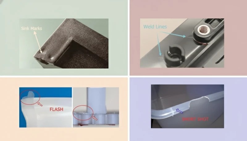
Плохая конструкция охлаждения создает пять взаимосвязанных проблем: коробление и отклонение размеров из-за неравномерных температурных градиентов свыше 5°C на поверхности полости; утяжины из-за недостаточного времени охлаждения, ведущего к преждевременному выталкиванию; внутренние остаточные напряжения из-за быстрого или неравномерного отверждения; поверхностные дефекты, включая различие в глянце и побеление; увеличенное время цикла из-за консервативных настроек охлаждения для компенсации плохого размещения каналов.
Все пять проблем стоят денег – будь то через брак, переделку, медленные циклы или проваленные проверки заказчика. По нашему опыту анализа сотен проектов форм, плохой дизайн охлаждения является наиболее частой первопричиной брака первых образцов. Клиенты часто приписывают неудачи материалу или настройкам машины, когда настоящая причина – охлаждающий контур, который никогда не был правильно спроектирован.
| Параметр | Плохое охлаждение | Оптимизированное охлаждение | Improvement |
|---|---|---|---|
| Время цикла | 35 сек | 22 сек | -37% |
| Равномерность температуры | >10°C delta | <3°C delta | в 3 раза лучше |
| Деформация (типичная деталь из ABS) | 0.8 mm | 0.15 мм | сокращение на 81% |
| Глубина утяжины | 0.3 mm | <0.05 mm | В 6 раз лучше |
| Годовая производительность (1 гнездо) | 825 000 выстрелов | 1 310 000 выстрелов | +59% |
These figures come from our engineering team’s internal benchmarking data across 200+ mold projects. The exact numbers vary by material, wall thickness, and part geometry — but the directional impact is consistent: every second of cooling time saved translates directly to cost reduction and capacity increase.
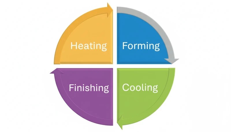
6 типов систем охлаждения литьевых форм
В литьевых формах используются шесть основных конфигураций охлаждающих каналов, каждая из которых подходит для разных геометрий деталей, требований к точности и бюджетных ограничений. Понимание того, когда использовать каждый тип, является основой проектирования форм.
1. Прямолинейные охлаждающие каналы
Прямолинейные (или просверленные) охлаждающие каналы являются стандартом для плоских или простых по геометрии деталей. Они создаются путем сверления отверстий диаметром 6–14 мм в плитах формы в виде сетки или параллельного рисунка. Расстояние от канала до полости обычно составляет 15–25 мм для форм из стали P20, при минимальной толщине стенки до поверхности полости в 1,5 раза больше диаметра канала. Скорость потока охлаждающей жидкости должна обеспечивать турбулентный поток (число Рейнольдса выше 10 000), который передает тепло в 3–5 раз эффективнее, чем ламинарный поток.
Прямые каналы — самый экономически эффективный вариант: стоимость сверления одного контура составляет 50–200 долларов против 500–5000 долларов за конформные каналы. Они полностью подходят для плоских крышек, панелей, корпусов с равномерной толщиной стенки и стандартных деталей. Их ограничение — геометрическое: они не могут повторять изогнутые или сложные поверхности полости, оставляя горячие точки в углах и ребрах, где канал по необходимости находится дальше от стенки полости.
2. Охлаждение с помощью перегородок (баффлов)
Перегородки (баффлы) — это тонкие металлические пластины, вставленные в просверленные каналы, которые заставляют охлаждающую жидкость течь вниз по одной стороне и возвращаться вверх по другой, превращая одно прямое отверстие в U-образный путь потока. Они используются в узких сердечниках, штифтах и областях, где нельзя просверлить два параллельных канала рядом. Типичная перегородка удваивает площадь охлаждающей поверхности в ограниченной зоне без необходимости в дополнительных портах каналов.
Эффективность перегородки зависит от зазора пластины (0,05–0,15 мм с каждой стороны) и скорости потока охлаждающей жидкости. Мы обычно применяем перегородки для сердечников диаметром от 16 до 40 мм. Для диаметров менее 16 мм более эффективны тепловые штифты или барботажные охладители; для диаметров более 40 мм предпочтительным вариантом становятся спиральные каналы. Именно сочетание геометрии перегородки и правильной скорости потока определяет разницу между адекватным и превосходным охлаждением сердечника.
3. Барботажное охлаждение
Барботажные охладители (также называемые фонтанирующим охлаждением) используют внутреннюю трубку малого диаметра, вставленную в глухое отверстие: охлаждающая жидкость течет вниз по внутренней трубке и возвращается вверх по кольцевому зазору между трубкой и стенкой отверстия. Это создает эффект распыления на кончике сердечника — самой горячей зоне — достигая очень высоких локальных коэффициентов теплопередачи. Барботажные охладители являются стандартом для сердечников диаметром менее 16 мм и глубоких штифтовых элементов с соотношением сторон выше 4:1.
В нашем цехе мы используем барботажные охладители на каждом штифте сердечника высотой более 25 мм, независимо от диаметра. Дополнительные затраты на обработку в размере 30–80 долларов за порт барботажного охладителя неизменно окупаются за счет сокращения времени цикла при испытании формы. Для сердечников, слишком маленьких для барботажных охладителей, вставки из бериллиевой меди обеспечивают пассивную теплопроводность к ближайшим водяным каналам.
4. Спиральные (винтовые) охлаждающие каналы
Спиральные охлаждающие каналы обвивают цилиндрические сердечники или круглые полости по винтовой траектории, обеспечивая равномерное охлаждение на 360 градусов элемента. Для резьбовых крышек, круглых контейнеров, медицинских флаконов и любых деталей с осевой симметрией спиральные каналы снижают разницу между пиковой и средней температурой с более чем 8 градусов Цельсия (при прямых каналах) до менее чем 2 градусов Цельсия.
Шаг и угол подъема настраиваются под скорость потока охлаждающей жидкости — обычно шаг 4–8 мм с углом спирали 45 градусов для водяного охлаждения. Спиральные вставки могут быть изготовлены как отдельные компоненты и запрессованы в сердечники формы, что делает их заменяемыми при износе или когда изменение геометрии требует перепроектирования.
5. Конформные охлаждающие каналы
conformal cooling4 каналы точно повторяют 3D-контур стенки полости формы на равном расстоянии (обычно 5-12 мм), что возможно благодаря металлической аддитивной технологии (DMLS или SLM). В то время как обычные сверлёные каналы оставляют горячие точки на криволинейных поверхностях и острых углах, конформные каналы сохраняют расстояние от полости до канала в пределах ±1 мм по всей поверхности — обеспечивая сокращение времени цикла на 20–35% и значительно более равномерное охлаждение.
The trade-off is cost and lead time: a conformal-cooled insert produced by DMLS from H13 tool steel costs $3,000-15,000 versus $500-2,000 for a conventionally machined insert. The break-even point is typically reached at 50,000-100,000 shots for high-volume parts, where cycle time savings translate to machine-hour savings that exceed the tooling premium. For medical devices, automotive trim, and consumer electronics at high volume, conformal cooling is the standard of practice.
6. Thermal Pins and Heat Pipes
Thermal pins (heat pipes) are sealed copper or beryllium copper components charged with a phase-change fluid. They passively transfer heat from hot spots — sharp corners, ribs, thin features — to a water-cooled heat sink with no active coolant flow. Heat pipe thermal conductivity reaches 10,000-100,000 W/m·K, compared to 20-50 W/m·K for P20 steel.
Thermal pins are ideal for features too small or inaccessible for active cooling channels, such as ribs under 3 mm wide or ejector pin areas. They require no plumbing connections and can be retrofitted into existing molds without major rework. In our factory, thermal pins have eliminated hot-spot sink marks on several medical device molds where ribs could not otherwise be adequately cooled.
Cooling Medium Comparison: Water, Oil, and Air
The cooling medium choice — water, oil, or air — determines heat transfer capacity, operating temperature range, maintenance requirements, and cost. Each medium fits a specific window of mold temperature requirements, and choosing the wrong medium creates quality problems that are surprisingly difficult to trace back to their root cause.
| Средний | Диапазон температур | Heat Transfer | Лучшее для | Техническое обслуживание |
|---|---|---|---|---|
| Water (chilled) | 10-60°C | High (3,000-10,000 W/m2K) | Most thermoplastics (PE, PP, ABS, PC) | Scale/corrosion control |
| Water (tower) | 25-35°C | Высокий | High-volume commodity parts | Algae and mineral control |
| Oil (thermal) | 60-200°C | Medium (500-2,000 W/m2K) | High-temp materials (PEI, PEEK, PPS) | Fluid replacement every 12 months |
| Воздух | Ambient | Low (50-200 W/m2K) | Thin walls, elastomers, foam parts | Minimal — filter cleaning only |
| Beryllium copper | Passive | Very high (conduction) | Thin ribs, micro features | None |
In our factory, 90% of molds run water cooling at 15-25 degrees C using a closed-loop chiller system. For engineering resins processed above 120 degrees C (PEI, PEEK, PPS, POM), we switch to temperature-controlled oil circuits that maintain mold temperature at 80-160 degrees C. Air cooling is reserved for simple silicone and thin-wall foam applications where water channel proximity would cause surface condensation.
Water chemistry management is a critical and often overlooked aspect of mold cooling. We use deionized water with pH 7-8 and a corrosion inhibitor package in all production chiller loops. Tap water causes progressive scale buildup that reduces heat transfer by 15-25% per millimeter of deposit — an invisible performance degradation that shows up as gradually increasing cycle times over 12-18 months of production.
True or False: Injection Mold Cooling Myths
“Cooling time accounts for more than half of total injection molding cycle time.”Правда
In most standard thermoplastic applications, cooling accounts for 50-70% of total cycle time. A 30-second cycle typically breaks down as: injection 3-5 sec, pack/hold 5-8 sec, cooling 15-22 sec, and ejection/mold-open 3-5 sec. Optimizing the cooling phase is the single highest-leverage action in cycle time reduction. Even a 20% improvement in cooling efficiency on a 20-second cooling window saves 4 seconds — a 13% cycle time reduction with no other changes.
“Using colder water always produces faster, better results in injection mold cooling.”Ложь
Dropping coolant temperature below the dew point causes condensation on the mold surface — forming water droplets that transfer to part surfaces as cosmetic defects, accelerate mold surface rust, and cause short shots. For hygroscopic materials like nylon and ABS, mold temperature must stay above 15 degrees C to prevent moisture-related defects. The optimal coolant temperature depends on material, wall thickness, ambient humidity, and surface finish requirements — not simply the lowest achievable temperature.
These two principles — that cooling dominates cycle time and that coolant temperature must be carefully controlled — form the foundation of effective injection mold cooling system engineering. Misunderstanding either one leads to wasted machine time or cosmetic defects that fail customer inspection. The next two myths address more advanced design decisions around coolant flow dynamics and cooling technology selection. Both are frequently misapplied in practice: engineers either accept laminar flow as unavoidable or invest in conformal cooling for parts that do not justify the premium. Getting the analysis right saves both time and money.
“Turbulent coolant flow transfers heat significantly more efficiently than laminar flow.”Правда
Turbulent flow (Reynolds number above 10,000) achieves convective heat transfer coefficients of 3,000-10,000 W/m2K, compared to 500-1,500 W/m2K for laminar flow — a 3-5 times improvement in heat transfer rate. Achieving turbulence requires minimum flow velocities of 0.5-1.0 m/s for 8 mm channels. We specify flow rate requirements on every mold cooling circuit drawing and verify turbulent conditions at the mold trial using digital flow meters on each circuit port.
“Conformal cooling channels always justify their higher cost over conventional straight channels.”Ложь
Conformal cooling is a premium solution justified only by high production volumes and geometrically complex parts. For flat panels, lids, and simple boxes running under 50,000 shots annually, the $10,000-30,000 DMLS tooling premium will never be recovered through cycle time savings. The break-even analysis must account for machine hourly rate, cycle time delta, annual volume, and tool life. For low-volume specialty parts, optimized straight channels deliver 90% of the benefit at 10% of the cost.
Key Design Parameters for Injection Mold Cooling
Five engineering parameters govern cooling system performance. Getting these right at the design stage prevents expensive rework after mold trials. These numbers are not arbitrary — they emerge from decades of empirical testing and thermal simulation validation.
Channel Diameter
Standard cooling channel diameters range from 6 mm (small precision molds) to 16 mm (large structural molds). The most common sizes in our shop are 8 mm and 10 mm, which balance drilling cost, flow resistance, and heat transfer surface area. Channels below 6 mm are prone to blockage from scale and corrosion and require filtered deionized water; channels above 16 mm reduce structural mold strength and increase the risk of channel-to-channel breakthrough during drilling.
Channel-to-Cavity Distance
Channel centerline-to-cavity surface distance should be 1.5-2 times the channel diameter for balanced thermal and structural performance. For an 8 mm channel in P20 steel, the target distance is 12-16 mm. Closer placement increases cooling rate but risks stress cracking and core breakthrough; greater distances reduce cooling efficiency and create hot spots between channels where the thermal gradient is not adequately controlled.
Шаг каналов (расстояние между центрами)
Шаг между параллельными каналами влияет на равномерность температуры по поверхности полости. Стандартная рекомендация составляет 3-5 диаметров канала. Для каналов 10 мм шаг 30-50 мм обеспечивает баланс между тепловой однородностью и стоимостью сверления. Больший шаг создает температурную пульсацию между каналами; меньший шаг структурно сложен и увеличивает стоимость плиты формы.

Расход охлаждающей жидкости и число Рейнольдса
Скорость потока должна обеспечивать число Рейнольдса выше 10 000 для турбулентного течения. Для канала 8 мм это требует скорости потока выше 0,7 м/с, что соответствует примерно 2,6 литрам в минуту на контур. Наша стандартная практика — проверять расход на испытании пресс-формы с помощью цифровых расходомеров, установленных на каждом порте контура, и записывать фактические числа Рейнольдса в лист настройки пресс-формы для будущего использования в производстве.
Разница температур на входе и выходе
Повышение температуры охлаждающей жидкости от входа к выходу должно оставаться ниже 3-5 градусов Цельсия на контур. Больший перепад указывает на недостаточный расход — охлаждающая жидкость поглощает слишком много тепла за один проход — и создает температурный градиент по длине канала, что приводит к неравномерному охлаждению от одного конца детали к другому. Мы стремимся к перепаду ниже 3 градусов Цельсия как к нашему стандарту и регулируем расход на испытаниях до его достижения.
Поэтапный процесс проектирования системы охлаждения
Наша инженерная команда следует структурированному семиэтапному процессу для каждой новой системы охлаждения формы, от первоначальной проверки CAD до валидации на испытаниях формы. Этот процесс устраняет большинство связанных с охлаждением дефектов первой отливки до их возникновения.
Шаг 1 — расчет тепловой нагрузки: оценка теплопритоков от массы впрыскиваемого пластика, энтальпии материала и целевого времени цикла для определения требуемой холодопроизводительности в ваттах. Шаг 2 — выбор типа каналов: соответствие геометрии каналов форме детали — прямые для плоских деталей, спиральные для цилиндрических элементов, конформные для сложной 3D-геометрии, перегородки и пузырьковые устройства для узких сердечников. Шаг 3 — проектирование расположения: размещение каналов на расстоянии 1.5-2 диаметра, с шагом 3-5 диаметров, с достаточными стальными перемычками между каналами.
Шаг 4 — планирование контуров: проектирование последовательных и параллельных контуров для балансировки потока и избегания мертвых зон, где скорость охлаждающей жидкости падает до нуля. Шаг 5 — моделирование течения в форме: проведение теплового анализа в Moldex3D или Moldflow для проверки равномерности температуры, выявления горячих точек и прогнозирования коробления — итерационная корректировка схемы до тех пор, пока разница между пиковой и средней температурой не упадет ниже 5 градусов Цельсия. Шаг 6 — проверка на технологичность изготовления: проверка на пересечение со штифтами выталкивателей, направляющими штифтами, подъемниками и слайдами. Шаг 7 — валидация на испытаниях формы: измерение расходов по контурам, разницы температур на входе/выходе и температуры детали при извлечении с помощью инфракрасной термометрии с последующим сравнением с прогнозами моделирования.
Распространенные проблемы систем охлаждения и их решения
Даже хорошо спроектированные системы охлаждения со временем развивают проблемы. Три наиболее частые проблемы, с которыми мы сталкиваемся на нашем заводе, — это образование накипи в каналах, горячие точки из-за слепых зон в конструкции и утечка охлаждающей жидкости в полость формы. У каждой есть четкие диагностические признаки и проверенные способы устранения.
| Проблема | Предотвращает образование утяжин на противоположной поверхности | Решение |
|---|---|---|
| Коробление / дрейф размеров | Неравномерная температура полости (>5°C разницы) | Добавить каналы к горячим зонам; проверить баланс потока |
| Накипь/засоренные каналы | Отложения минералов из жесткой воды | Использовать деионизированную воду; ежегодная кислотная промывка |
| Утечка охлаждающей жидкости в полость формы | Трещина в стенке канала (недостаточная толщина стали) | Перепроектировать со стенкой >10 мм; использовать уплотнительные кольца на вставках |
| Увеличенное время цикла | Недостаточная скорость потока (ламинарный поток) | Увеличить давление насоса; сократить длину контура; изменить размер каналов |
| Поверхностная конденсация/ржавчина | Охлаждающая жидкость ниже точки росы | Повысить температуру охлаждающей жидкости; использовать влагозащитные барьеры |
| Горячие точки на ребрах/тонких стенках | Каналы слишком далеко от элемента | Добавить пузырьковые устройства, перегородки или тепловые штифты в проблемных зонах |
По нашему опыту, образование накипи — главный долгосрочный "убийца" охлаждения. Слой накипи толщиной 1 мм на стенке канала снижает теплопередачу примерно на 15-25%. Мы предписываем ежеквартальные проверки контуров охлаждения на всех производственных формах, с кислотной очисткой от накипи каждые 6-12 месяцев в зависимости от жесткости воды. Формы, работающие на городской воде, требуют более частого обслуживания, чем те, что подключены к контурам с деионизированной водой.
Утечка охлаждающей жидкости в полость пресс-формы встречается реже, но при возникновении катастрофически разрушительна — производство немедленно останавливается, и пресс-форма требует ремонта. Основная причина — недостаточная толщина стенки между охлаждающим каналом и поверхностью полости, обычно из-за канала, просверленного слишком близко при изготовлении, или трещины, распространившейся из ранее существовавшего дефекта поверхности. Мы проверяем минимальную толщину стенки во время анализа DFM и повторно проверяем с помощью измерения КИМ после механической обработки, до любых испытаний пресс-формы.
Конформное охлаждение против традиционного: когда выбирать
Конформное охлаждение не всегда является правильным решением. Структура принятия решения проста: сравните надбавку к стоимости оснастки со стоимостью экономии времени цикла на запланированном объеме производства. Ошибка в этом анализе в любую сторону стоит денег — либо из-за перерасхода на премиальную оснастку для детали с малым объемом, либо из-за упущенной значительной экономии времени цикла для детали с большим объемом.
| Фактор | Выбрать традиционный | Выбрать конформное охлаждение |
|---|---|---|
| Геометрия детали | Плоская, равномерная толщина стенки | Сложная 3D, переменная толщина стенки |
| Annual volume | <50,000 shots | >100 000 выстрелов |
| Целевое время цикла | Нет жестких ограничений | Требуется снижение 20%+ |
| Допуск на коробление | Допустимо +/-0,5 мм | <+/-0,2 мм требуется |
| Бюджет на оснастку | Стандартный бюджет | 20-50% премиум допустим |
| Материал | PE, PP, ABS (нестрогие) | PC/ABS, нейлон, инженерные пластики (чувствительные) |
На нашей фабрике мы рекомендуем конформное охлаждение для автомобильного внешнего декора, корпусов медицинских устройств и деталей потребительской электроники, где косметические стандарты строги, толщина стенок значительно варьируется и годовые объёмы превышают 100 000 циклов. Для упаковки, стандартных корпусов и прототипных инструментов оптимизированное традиционное охлаждение обеспечивает требуемое качество при значительно меньшей стоимости. Решение должно приниматься на этапе анализа DFM — не после того, как первое испытание формы выявит проблему с циклом.
Изменяющаяся стоимость технологии конформного охлаждения
Экономика конформного охлаждения значительно изменилась за последние пять лет, поскольку стоимость оборудования DMLS (Direct Metal Laser Sintering) снизилась на 40-60%, а сроки выполнения сократились с 8 недель до 2-3 недель. В 2020 году конформное охлаждение было оправдано преимущественно для автомобильных и медицинских применений. Сегодня мы всё чаще рекомендуем его для любой детали с соотношением толщины стенок выше 2:1, где годовой объём превышает 75 000 циклов. Расчет точки безубыточности теперь часто указывает на преимущество конформного охлаждения в применениях, которые всего несколько лет назад автоматически использовали традиционные каналы.
Одно недооцененное преимущество конформного охлаждения — его влияние на стабильность детали, не только на скорость. Когда распределение температуры равномерно в пределах 2-3 градусов C, размерные отклонения между циклами существенно уменьшаются — фактор, чрезвычайно важный в производстве медицинских устройств и точных автомобильных компонентов, где требования Cpk выше 1.67 являются стандартом. На нашей фабрике переход трех форм для медицинских устройств от традиционного к конформному охлаждению снизил размерное технологическое отклонение на 35-45%, устранив значительный источник брака при проверке на уровне клиента.

Часто задаваемые вопросы о системах охлаждения литьевых форм
Сколько времени должно составлять время охлаждения при литье под давлением?
Время охлаждения зависит от толщины стенки, теплопроводности материала, температуры формы и требуемой температуры выталкивания. Общее правило: время охлаждения в секундах приблизительно равно толщине стенки в миллиметрах в квадрате, умноженной на коэффициент материала 1.5-2.5 для аморфных пластиков (ABS, PC) и 2.0-4.0 для полукристаллических пластиков (PP, PA, POM). Для стенки ABS толщиной 3 мм ожидается 9-13 секунд охлаждения; для стенки PP толщиной 3 мм — 18-36 секунд. Наша инженерная команда рассчитывает требуемое время охлаждения во время анализа DFM с использованием инструментов теплового моделирования — не только общих правил — потому что разница толщины стенок на одной детали может требовать очень разных продолжительностей охлаждения для разных участков.
Что вызывает коробление в деталях, изготовленных методом литья под давлением?
Деформация вызвана дифференциальным усадкой по детали, которая возникает из-за неравномерного охлаждения. Когда одна поверхность охлаждается быстрее противоположной, она усаживается больше, изгибая деталь к более холодной стороне. Разница температур более 5-8 градусов C между сторонами полости и сердечника является наиболее распространенной первопричиной. Другими факторами включают асимметричную толщину стенок, недостаточное давление подпрессовки, расположение литника и эффекты ориентации волокон в стеклонаполненных материалах. Основное решение — балансировка схемы охлаждающих каналов, подтвержденная анализом потока в форме с тепловым моделированием до начала обработки стали. Попытки исправить деформацию только через корректировки давления подпрессовки редко успешны, если первопричина находится в конструкции охлаждения.
Как рассчитать диаметр и расстояние между охлаждающими каналами?
Стандартные отраслевые рекомендации по проектированию каналов охлаждения: диаметр канала должен составлять 6–16 мм (чаще всего 8–10 мм для стандартной оснастки); расстояние от осевой линии канала до поверхности полости должно быть в 1,5–2,0 раза больше диаметра канала; шаг каналов (расстояние между осями) должен составлять 3–5 диаметров канала. Для канала диаметром 10 мм целевое расстояние до полости составляет 15–20 мм, а шаг — 30–50 мм. Эти исходные параметры проверяются с помощью теплового моделирования в Moldex3D или Moldflow, чтобы убедиться, что разница между максимальной и средней температурой по всей поверхности полости не превышает 5 градусов Цельсия в условиях полного производства, до начала механической обработки стали.
В чем разница между последовательными и параллельными контурами охлаждения?
В последовательной цепи охлаждающая жидкость проходит через все каналы по одному непрерывному пути перед выходом из формы. Это просто в реализации, но приводит к значительному повышению температуры охлаждающей жидкости от входа к выходу, создавая температурный градиент, который вызывает неравномерное охлаждение по длине изделия. В параллельной цепи поток охлаждающей жидкости разделяется между несколькими каналами одновременно и объединяется на выходном коллекторе, обеспечивая более равномерное распределение температуры по всей форме. Большинство производственных форм используют комбинированный подход: короткие последовательные цепи для отдельных зон, сбалансированные через параллельные коллекторы по всей форме, чтобы обеспечить одинаковую температуру охлаждающей жидкости на входе в каждую зону.
Почему в моей форме возникают горячие точки, даже при наличии системы охлаждения?
Тепловые точки возникают, когда охлаждающие каналы слишком далеко от поверхности полости, когда скорость потока недостаточна и создает условия ламинарного потока, когда накопление накиди изолирует каналы от эффективного теплообмена, или когда определенные элементы — тонкие ребра, острые углы, маленькие сердечники — недоступны для традиционных каналов. Решения включают добавление пузырьковых каналов или тепловых штифтов к недоступным элементам, проверку условий турбулентного потока на испытании с цифровыми расходомерами, выполнение ежегодной кислотной очистки от накиди на всех каналах и переход на конформные охлаждающие вставки в хронически горячих зонах, идентифицированных через картирование температуры детали инфракрасным методом после выталкивания.
-
cycle time: Цикл — это общая продолжительность одного полного цикла литья под давлением, измеряемая в секундах, включающая фазы впрыска, охлаждения и выталкивания. ↩
-
DFM: DFM (Design for Manufacturability) — это инженерная методология, которая оптимизирует дизайн продукта для повышения эффективности и рентабельности производственного процесса. ↩
-
mold flow analysis: Анализ потока в форме — это процесс компьютерного моделирования, который предсказывает, как расплавленный пластик заполняет полость формы, включая поведение охлаждения, деформацию и усадку. ↩
-
conformal cooling: Конформное охлаждение относится к технологии охлаждения формы, где каналы проектируются для следования контуру полости формы, обеспечивая равномерное удаление тепла на сложных геометриях детали. ↩


