 Zum Inhalt springen

- Die Kühlung macht 50-70 % der gesamten Spritzgusszykluszeit aus; ihre Optimierung ist der schnellste Weg, um Kosten zu senken.
- Die sechs Haupttypen von Kühlkanälen sind: geradlinige, Umlenkbleche, Sprudler, spiralförmige, konforme und Wärmestifte.
- Wasserkühlung bei 10–25 °C ist der Industriestandard für die meisten Thermoplaste; Ölkühlung wird über 80 °C eingesetzt.
- Konforme Kühlkanäle reduzieren die Zykluszeit um 20–35 % im Vergleich zu konventionellen geraden Kanälen.
- Kanaldurchmesser, Teilung und Abstand von der Kavitätswand bestimmen direkt die Kühlgleichmäßigkeit und das Verzugrisiko.
- In unserer Fabrik setzen wir für jede neue Form eine Fließanalyse ein, um die Temperaturgleichmäßigkeit vor der Stahlbearbeitung zu überprüfen.
Was ist ein Kühlsystem für Spritzgussformen?
Ein Spritzgussform-Kühlsystem ist ein Netzwerk aus Kanälen, Durchgängen und Temperaturregelvorrichtungen, die in die Form eingearbeitet sind und die Wärme aus dem geschmolzenen Kunststoff nach dem Einspritzen abführen, wodurch Zykluszeit1 um 50-70% und gewährleistet Maßhaltigkeit. Ohne ein richtig ausgelegtes Kühlsystem verziehen sich Teile, es entstehen Einfallstellen und der Produktionsdurchsatz bricht ein. Das Kühlsystem ist kein nachträglicher Gedanke – es entscheidet, ob Ihre Form profitabel ist oder eine Belastung darstellt.
Die Kühlung erfolgt durch Zirkulation eines temperaturgeregelten Mediums – meist Wasser bei 10–25 °C – durch Kanäle, die in die Kavität umgebenden Formplatten gebohrt oder gedruckt sind. Die Wärme aus der geschmolzenen Kunststoffmasse (eingespritzt bei 180–320 °C, je nach Material) wird an das Kühlmittel übertragen, das sie zu einem externen Kühler oder Kühlturm abführt. Das Bauteil erreicht die Ausstoßtemperatur (typischerweise 40–80 °C unterhalb der Glasübergangstemperatur des Materials) und wird entnommen.
In unserer Fabrik in China betreiben wir 47 Spritzgießmaschinen in 3 Werkstätten. Jede von uns gebaute Form erhält während DFM2 Überprüfung, und wir verwenden Moldflow-Analyse3 um die Temperaturverteilung zu simulieren, bevor Stahl bearbeitet wird. Diese Disziplin ist der Grund, warum unsere Erstfreigaberate 92 % übersteigt.
Warum das Design des Kühlsystems wichtig ist: Die Zahlen
Die Kühlphase macht 50-70% der gesamten Zykluszeit beim Standard-Spritzgießen von Thermoplasten aus. Eine Reduzierung der Kühlzeit um 10 Sekunden bei einem 30-Sekunden-Zyklus bedeutet eine Steigerung des Durchsatzes um 33% – das sind Hunderttausende mehr Teile pro Jahr auf derselben Maschine ohne Kapitalinvestition. Das ist die Optimierung mit der höchsten ROI im Spritzgießen.
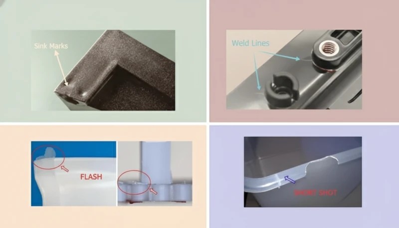
Schlechtes Kühldesign verursacht fünf zusammenhängende Probleme: Verzug und Maßabweichung durch ungleichmäßige Temperaturgradienten von über 5 °C über die Kavitätsoberfläche; Einfallstellen durch unzureichende Kühlzeit, die zu vorzeitigem Ausstoßen führen; innere Eigenspannungen durch schnelle oder ungleichmäßige Erstarrung; Oberflächendefekte einschließlich Glanzunterschieden und Mattierungen; und verlängerte Zykluszeiten durch konservative Kühleinstellungen, um schlechte Kanalplatzierung auszugleichen.
Alle fünf Probleme kosten Geld – entweder durch Ausschuss, Nacharbeit, langsame Zyklen oder gescheiterte Kundenprüfungen. Nach unserer Erfahrung bei der Prüfung von Hunderten von Formenprojekten ist eine schlechte Kühlauslegung die häufigste Hauptursache für Fehler beim Erstmuster. Kunden führen Fehler oft auf Material oder Maschineneinstellungen zurück, während die eigentliche Ursache ein nie richtig ausgelegter Kühlkreislauf ist.
| Parameter | Schlechte Kühlung | Optimierte Kühlung | Improvement |
|---|---|---|---|
| Zykluszeit | 35 Sek | 22 Sekunden | -37% |
| Temperaturgleichmäßigkeit | >10°C Delta | <3°C Delta | 3x besser |
| Verzug (typisches ABS-Bauteil) | 0.8 mm | 0,15 mm | 81 % Reduktion |
| Einfalltiefe | 0.3 mm | <0,05 mm | 6x besser |
| Jährlicher Durchsatz (1 Kavität) | 825.000 Schüsse | 1.310.000 Schüsse | +59% |
Diese Zahlen stammen aus den internen Benchmark-Daten unseres Ingenieurteams von über 200 Formenprojekten. Die genauen Zahlen variieren je nach Material, Wandstärke und Teilegeometrie – aber die Richtung des Einflusses ist konsistent: Jede eingesparte Sekunde Kühlzeit führt direkt zu Kostensenkung und Kapazitätssteigerung.
6 Arten von Kühlsystemen für Spritzgussformen
Spritzgussformen verwenden sechs primäre Kühlkanalkonfigurationen, die jeweils für verschiedene Bauteilgeometrien, Präzisionsanforderungen und Budgetbeschränkungen geeignet sind. Zu verstehen, wann welcher Typ einzusetzen ist, ist grundlegend für das Formendesign.
1. Geradlinige Kühlkanäle
Geradlinige (oder gebohrte) Kühlkanäle sind der Standard für flache oder einfach geformte Bauteile. Sie werden durch Bohren von Löchern mit 6–14 mm Durchmesser durch Formplatten in einem Raster oder parallelen Muster erzeugt. Der Kanal-Kavitäts-Abstand beträgt typischerweise 15–25 mm für P20-Stahlformen, mit dem 1,5-fachen Kanaldurchmesser als Mindestwandstärke zur Kavitätsoberfläche. Die Kühlmittelfließgeschwindigkeit zielt auf turbulente Strömung (Reynolds-Zahl über 10.000) ab, die Wärme 3–5 mal effizienter überträgt als laminare Strömung.
Gerade Kanäle sind die kostengünstigste Option – die Bohrungskosten betragen $50-200 pro Kreislauf gegenüber $500-5.000 für konforme Kanäle – und sind vollkommen geeignet für flache Deckel, Paneele, Gehäuse mit gleichmäßiger Wandstärke und Standardteile. Ihre Einschränkung ist geometrisch: Sie können gekrümmten oder komplexen Kavitätsoberflächen nicht folgen, wodurch Hotspots in Ecken und Rippen entstehen, wo der Kanal zwangsläufig weiter von der Kavitätswand entfernt ist.
2. Prallkühlung
Umlenkbleche sind dünne Metallplatten, die in gebohrte Kanäle eingesetzt werden und das Kühlmittel zwingen, auf einer Seite hinab und auf der anderen zurückzufließen, wodurch ein einzelnes gerades Loch in einen U-förmigen Strömungsweg umgewandelt wird. Sie werden in schmalen Kernen, Stiften und Bereichen eingesetzt, wo zwei parallele Kanäle nicht nebeneinander gebohrt werden können. Ein typisches Umlenkblech verdoppelt die Kühloberfläche in einem beengten Bereich, ohne zusätzliche Kanalanschlüsse zu benötigen.
Die Wirksamkeit von Umlenkblechen hängt vom Plattenabstand (0,05-0,15 mm auf jeder Seite) und der Kühlmittelströmungsgeschwindigkeit ab. Wir empfehlen typischerweise Umlenkbleche für jeden Kerndurchmesser zwischen 16 und 40 mm. Unter 16 mm sind Wärmestifte oder Sprudler effektiver; über 40 mm werden spiralförmige Kanäle zur bevorzugten Option. Die Kombination aus Umlenkblechgeometrie und geeigneter Durchflussrate macht den Unterschied zwischen ausreichender und hervorragender Kernkühlung aus.
3. Sprudelkühlung
Sprudler (auch Springbrunnenkühlung genannt) verwenden ein Innendünnrohr, das in ein Sackloch eingeführt wird: Kühlmittel fließt das Innendünnrohr hinab und steigt im Ringspalt zwischen Rohr und Bohrungswand wieder auf. Dies erzeugt einen Sprühnebel an der Spitze des Kerns – der heißesten Zone – und erreicht sehr hohe lokale Wärmeübergangskoeffizienten. Sprudler sind Standard für Kerne mit einem Durchmesser unter 16 mm und für tiefe Stiftgeometrien mit einem Seitenverhältnis über 4:1.
In unserer Werkstatt verwenden wir Sprudler für jeden Kernstift über 25 mm Höhe, unabhängig vom Durchmesser. Die zusätzlichen Bearbeitungskosten von $30-80 pro Sprudleranschluss werden durch die Zykluszeitverkürzung beim Formenversuch regelmäßig wieder eingespielt. Für Kerne, die für Sprudler zu klein sind, sorgen Beryllium-Kupfer-Einsätze für passive Wärmeleitung zu nahegelegenen Wasserkreisläufen.
4. Spiralförmige (Helix) Kühlkanäle
Spiralförmige Kühlkanäle verlaufen schraubenförmig um zylindrische Kerne oder runde Kavitäten und sorgen für eine gleichmäßige Kühlung über 360° des Elements. Für Schraubverschlüsse, runde Behälter, Medizinfläschchen und alle rotationssymmetrischen Bauteile reduzieren Spiral-Kanäle die Temperaturdifferenz zwischen Maximum und Durchschnitt von über 8 °C (mit geraden Kanälen) auf unter 2 °C.
Steigung und Steigungswinkel sind auf die Kühlmittelfließgeschwindigkeit abgestimmt – typischerweise 4–8 mm Steigung mit einem 45°-Helixwinkel für Wasserkühlung. Spiral-Einsätze können als separate Komponenten gefertigt und in Formkerne gepresst werden, was sie austauschbar macht, wenn sie verschlissen sind oder wenn Geometrieänderungen eine Neukonstruktion erfordern.
5. Konforme Kühlkanäle
conformal cooling4 Kanäle folgen exakt der 3D-Kontur der Kavitätswand des Werkzeugs mit einem gleichmäßigen Abstand (typischerweise 5–12 mm), ermöglicht durch metallische additive Fertigung (DMLS oder SLM). Während herkömmliche gebohrte Kanäle Hotspots auf gekrümmten Flächen und scharfen Kanten hinterlassen, halten konforme Kanäle den Kavität-zu-Kanal-Abstand über die gesamte Fläche innerhalb von plus/minus 1 mm – was eine Zykluszeitreduktion von 20–35 % und deutlich gleichmäßigere Kühlung liefert.
Der Kompromiss sind Kosten und Lieferzeit: Ein durch DMLS aus Werkzeugstahl H13 gefertigtes konform gekühltes Einsatzstück kostet 3.000–15.000 € gegenüber 500–2.000 € für ein konventionell gefrästes Einsatzstück. Die Gewinnschwelle wird typischerweise bei 50.000–100.000 Zyklen für Hochvolumenteile erreicht, wo Zykluszeiteinsparungen zu Maschinenstundeneinsparungen führen, die den Werkzeugaufschlag übersteigen. Für Medizinprodukte, Automobilzierleisten und Unterhaltungselektronik in hohen Stückzahlen ist konforme Kühlung der Standard.
6. Wärmestifte und Heatpipes
Wärmestifte (Heatpipes) sind versiegelte Kupfer- oder Berylliumkupferkomponenten, die mit einem Phasenwechselfluid gefüllt sind. Sie übertragen passiv Wärme von Hotspots – scharfen Ecken, Rippen, dünnen Elementen – zu einem wassergekühlten Kühlkörper ohne aktiven Kühlmittelfluss. Die Wärmeleitfähigkeit von Heatpipes erreicht 10.000-100.000 W/m·K, verglichen mit 20-50 W/m·K für P20-Stahl.
Thermische Stifte sind ideal für Merkmale, die zu klein oder für aktive Kühlkanäle unzugänglich sind, wie z. B. Rippen unter 3 mm Breite oder Auswerferstiftbereiche. Sie benötigen keine Leitungsanschlüsse und können in bestehende Werkzeuge nachgerüstet werden, ohne größere Überarbeitung. In unserem Werk haben thermische Stifte Hotspot-Einfallstellen bei mehreren Medizinproduktwerkzeugen beseitigt, bei denen Rippen anderweitig nicht ausreichend gekühlt werden konnten.
Kühlmedium-Vergleich: Wasser, Öl und Luft
Die Wahl des Kühlmediums – Wasser, Öl oder Luft – bestimmt die Wärmeübertragungskapazität, den Betriebstemperaturbereich, die Wartungsanforderungen und die Kosten. Jedes Medium passt in ein spezifisches Fenster der Werkzeugtemperaturanforderungen, und die Wahl des falschen Mediums verursacht Qualitätsprobleme, die überraschend schwer auf ihre Ursache zurückzuführen sind.
| Mittel | Temperaturbereich | Wärmeübertragung | Am besten für | Wartung |
|---|---|---|---|---|
| Wasser (gekühlt) | 10-60°C | Hoch (3.000-10.000 W/m2K) | Die meisten Thermoplaste (PE, PP, ABS, PC) | Kalk-/Korrosionskontrolle |
| Wasser (Kühlturm) | 25–35 °C | Hoch | High-volume commodity parts | Algen- und Mineralienkontrolle |
| Öl (thermisch) | 60-200°C | Mittel (500–2.000 W/m²K) | Hochtemperaturmaterialien (PEI, PEEK, PPS) | Fluidaustausch alle 12 Monate |
| Luft | Umgebung | Niedrig (50-200 W/m²K) | Dünne Wände, Elastomere, Schaumteile | Minimal – nur Filterreinigung |
| Berylliumkupfer | Passiv | Sehr hoch (Leitung) | Dünne Rippen, Mikrostrukturen | None |
In unserem Werk laufen 90 % der Werkzeuge mit Wasserkühlung bei 15–25 °C über ein geschlossenes Kühlsystem. Für technische Kunststoffe, die über 120 °C verarbeitet werden (PEI, PEEK, PPS, POM), schalten wir auf temperaturgeregelte Ölkreisläufe um, die die Werkzeugtemperatur bei 80–160 °C halten. Luftkühlung wird für einfache Silikon- und Dünnwandschaumanwendungen reserviert, wo die Nähe von Wasserkanälen zu Oberflächenkondensation führen würde.
Das Wasserchemie-Management ist ein kritischer und oft übersehener Aspekt der Werkzeugkühlung. Wir verwenden in allen Produktionskühlkreisläufen deionisiertes Wasser mit pH 7–8 und einem Korrosionsinhibitor-Paket. Leitungswasser verursacht fortschreitende Ablagerungen, die die Wärmeübertragung um 15–25 % pro Millimeter Ablagerung reduzieren – eine unsichtbare Leistungsverschlechterung, die sich als allmählich steigende Zykluszeiten über 12–18 Monate Produktion zeigt.
Wahr oder Falsch: Mythen über die Spritzgusskühlung
„Die Abkühlzeit macht mehr als die Hälfte der gesamten Spritzgießzykluszeit aus.“Wahr
Bei den meisten Standard-Thermoplastanwendungen macht die Kühlung 50-70 % der gesamten Zykluszeit aus. Ein 30-Sekunden-Zyklus gliedert sich typischerweise wie folgt auf: Einspritzen 3-5 Sek., Nachdruck/Halten 5-8 Sek., Kühlen 15-22 Sek. und Auswerfen/Werkzeugöffnen 3-5 Sek. Die Optimierung der Kühlphase ist die effektivste Maßnahme zur Reduzierung der Zykluszeit. Selbst eine 20 %ige Verbesserung der Kühleffizienz bei einem 20-Sekunden-Kühlfenster spart 4 Sekunden – eine 13 %ige Reduzierung der Zykluszeit ohne weitere Änderungen.
„Die Verwendung kälteren Wassers führt bei der Spritzgusswerkzeugkühlung immer zu schnelleren und besseren Ergebnissen.“Falsch
Das Absenken der Kühlmitteltemperatur unter den Taupunkt verursacht Kondensation auf der Werkzeugoberfläche – es bilden sich Wassertropfen, die als kosmetische Fehler auf die Teileoberfläche übertragen werden, die Werkzeugoberflächenrostung beschleunigen und zu Kurzschüssen führen. Für hygroskopische Materialien wie Nylon und ABS muss die Werkzeugtemperatur über 15 °C bleiben, um feuchtigkeitsbedingte Fehler zu vermeiden. Die optimale Kühlmitteltemperatur hängt von Material, Wandstärke, Umgebungsluftfeuchtigkeit und Oberflächengüteanforderungen ab – nicht einfach von der niedrigsten erreichbaren Temperatur.
Diese beiden Grundsätze – dass die Kühlung die Zykluszeit dominiert und dass die Kühlmitteltemperatur sorgfältig geregelt werden muss – bilden die Grundlage einer effektiven Spritzgusswerkzeugkühlung. Ein Missverständnis in einem der beiden Punkte führt zu verschwendeter Maschinenzeit oder kosmetischen Fehlern, die bei der Kundenprüfung durchfallen. Die nächsten beiden Mythen behandeln fortgeschrittenere Designentscheidungen bezüglich der Kühlmittelflussdynamik und der Kühltechnologieauswahl. Beide werden in der Praxis häufig falsch angewendet: Ingenieure akzeptieren entweder laminare Strömung als unvermeidlich oder investieren in konforme Kühlung für Teile, die den Aufpreis nicht rechtfertigen. Eine korrekte Analyse spart sowohl Zeit als auch Geld.
„Turbulente Kühlmittelströmung überträgt Wärme deutlich effizienter als laminare Strömung.“Wahr
Turbulente Strömung (Reynolds-Zahl über 10.000) erreicht konvektive Wärmeübergangskoeffizienten von 3.000–10.000 W/m²K, verglichen mit 500–1.500 W/m²K für laminare Strömung – eine 3- bis 5-fache Verbesserung der Wärmeübertragungsrate. Turbulenz erfordert Mindestströmungsgeschwindigkeiten von 0,5–1,0 m/s für 8-mm-Kanäle. Wir legen Durchflussanforderungen in jeder Werkzeugkühlkreislaufzeichnung fest und überprüfen turbulente Bedingungen beim Werkzeugversuch mit digitalen Durchflussmessern an jedem Kreislaufanschluss.
„Konforme Kühlkanäle rechtfertigen immer ihre höheren Kosten gegenüber herkömmlichen geraden Kanälen.“Falsch
Konforme Kühlung ist eine Premiumlösung, die nur durch hohe Stückzahlen und geometrisch komplexe Teile gerechtfertigt ist. Für flache Paneele, Deckel und einfache Boxen mit weniger als 50.000 Zyklen pro Jahr wird der DMLS-Werkzeugaufpreis von 10.000-30.000 € niemals durch Zykluszeiteinsparungen amortisiert. Die Break-Even-Analyse muss Maschinenstundensatz, Zykluszeitdifferenz, Jahresvolumen und Werkzeuglebensdauer berücksichtigen. Für Kleinserien-Spezialteile bieten optimierte gerade Kanäle 90 % des Nutzens bei 10 % der Kosten.
Wichtige Designparameter für die Spritzgusskühlung
Fünf technische Parameter bestimmen die Leistung des Kühlsystems. Diese bereits im Designstadium richtig zu machen, verhindert teure Nacharbeit nach Werkzeugversuchen. Diese Zahlen sind nicht willkürlich – sie ergeben sich aus jahrzehntelanger empirischer Erprobung und Validierung durch thermische Simulation.
Channel Diameter
Standard-Kühlkanaldurchmesser reichen von 6 mm (kleine Präzisionsformen) bis 16 mm (große Strukturformen). Die häufigsten Größen in unserer Werkstatt sind 8 mm und 10 mm, die Bohrkosten, Strömungswiderstand und Wärmeübertragungsfläche in Einklang bringen. Kanäle unter 6 mm sind anfällig für Verstopfung durch Kalk und Korrosion und erfordern gefiltertes deionisiertes Wasser; Kanäle über 16 mm verringern die strukturelle Formfestigkeit und erhöhen das Risiko eines Durchbruchs zwischen den Kanälen während des Bohrens.
Kanal-zu-Kavitäts-Abstand
Der Abstand von der Kanalmittellinie zur Kavitätenoberfläche sollte das 1,5- bis 2-fache des Kanaldurchmessers betragen, um eine ausgewogene thermische und strukturelle Leistung zu erzielen. Für einen 8-mm-Kanal in P20-Stahl beträgt der Zielabstand 12-16 mm. Eine nähere Platzierung erhöht die Kühlrate, birgt aber das Risiko von Spannungsrissen und Kernbruch; größere Abstände verringern die Kühleffizienz und erzeugen Hotspots zwischen den Kanälen, wo der Temperaturgradient nicht ausreichend kontrolliert wird.
Kanalabstand (Mittenabstand)
Der Abstand zwischen parallelen Kanälen beeinflusst die Temperaturgleichmäßigkeit über die Kavitätsoberfläche. Die Standardempfehlung ist das 3-5-fache des Kanaldurchmessers. Für 10-mm-Kanäle sorgt ein Abstand von 30-50 mm für ein Gleichgewicht zwischen thermischer Gleichmäßigkeit und Bohrkosten. Ein größerer Abstand erzeugt Temperaturwellen zwischen den Kanälen; ein engerer Abstand ist strukturell anspruchsvoll und erhöht die Kosten der Formplatte.

Kühlmitteldurchflussrate und Reynolds-Zahl
Die Durchflussrate muss eine Reynolds-Zahl über 10.000 für turbulente Strömung erreichen. Für einen 8-mm-Kanal erfordert dies eine Strömungsgeschwindigkeit über 0,7 m/s, was etwa 2,6 Litern pro Minute pro Kreislauf entspricht. Unsere Standardpraxis ist es, die Durchflussrate beim Werkzeugversuch mit digitalen Durchflussmessern zu überprüfen, die an jedem Kreislaufanschluss installiert sind, und die tatsächlichen Reynolds-Zahlen im Werkzeugeinrichtungsblatt für zukünftige Produktionsreferenzen zu erfassen.
Einlass- und Auslasstemperaturdifferenz
Der Temperaturanstieg vom Kühlmitteleinlass zum -auslass sollte pro Kreislauf unter 3-5 Grad C bleiben. Ein größeres Delta deutet auf eine unzureichende Durchflussrate hin – das Kühlmittel nimmt pro Durchlauf zu viel Wärme auf – und erzeugt einen Temperaturgradienten entlang der Kanallänge, der zu einer ungleichmäßigen Kühlung von einem Ende des Teils zum anderen führt. Wir streben ein Delta unter 3 Grad C als unseren Standard an und passen die Durchflussrate beim Versuch an, bis dies erreicht ist.
Schritt-für-Schritt-Designprozess für Kühlsysteme
Unser Engineering-Team folgt einem strukturierten siebenstufigen Prozess für jedes neue Formkühlsystem, von der ersten CAD-Prüfung bis zur Formversuchsvalidierung. Dieser Prozess verhindert die meisten kühlungsbedingten Erstmusterfehler, bevor sie auftreten.
Schritt 1 ist die thermische Lastberechnung: Schätzen Sie den Wärmeeintrag aus der eingespritzten Kunststoffmasse, die Materialenthalpie und das Zykluszeit-Ziel, um die erforderliche Kühlleistung in Watt zu definieren. Schritt 2 ist die Auswahl des Kanaltyps: Passen Sie die Kanalgeometrie an die Teilform an – gerade für flache Teile, spiralförmig für zylindrische Merkmale, konform für komplexe 3D-Geometrien, Leitbleche und Sprudler für schmale Kerne. Schritt 3 ist das Layout-Design: Positionieren Sie die Kanäle mit einem Abstand von 1,5-2-fachem Durchmesser, einem Abstand von 3-5-fachem Durchmesser und ausreichenden Stahlbrücken zwischen den Kanälen.
Schritt 4 ist die Kreislaufplanung: Serien- und Parallelkreisläufe entwerfen, um den Durchfluss auszugleichen und Totzonen zu vermeiden, in denen die Kühlmittelgeschwindigkeit auf null sinkt. Schritt 5 ist die Formfüllsimulation: Thermische Analyse in Moldex3D oder Moldflow durchführen, um Temperaturgleichmäßigkeit zu überprüfen, Hotspots zu identifizieren und Verzug vorherzusagen – Layout iterativ anpassen, bis die Temperaturdifferenz zwischen Spitzen- und Durchschnittswert unter 5 Grad C fällt. Schritt 6 ist die DFM-Überprüfung: Prüfung auf Bohrungskollisionen mit Auswerfern, Führungsstiften, Liftern und Schiebern. Schritt 7 ist die Formversuchsvalidierung: Messung der Kreislaufdurchflussraten, Einlass-/Auslasstemperaturdifferenz und Teiletemperatur beim Auswerfen mittels Infrarotthermometrie, dann Vergleich mit Simulationsvorhersagen.
Häufige Probleme und Lösungen für Kühlsysteme
Auch gut konstruierte Kühlsysteme entwickeln mit der Zeit Probleme. Die drei häufigsten Probleme, auf die wir in unserer Fabrik stoßen, sind Kanalverkalkung, Hotspots durch konstruktive Blindbereiche und Kühlmittelleckagen in den Formhohlraum. Jedes hat klare Diagnoseindikatoren und bewährte Abhilfemaßnahmen.
| Problem | Verhindert Einfallstellen auf der gegenüberliegenden Oberfläche | Lösung |
|---|---|---|
| Verzug / Maßabweichung | Ungleichmäßige Kavitätentemperatur (>5°C Delta) | Kanäle zu heißen Zonen hinzufügen; Durchflussgleichgewicht überprüfen |
| Verkalkung/verstopfte Kanäle | Ablagerungen durch hartes Wasser | Verwendung von deionisiertem Wasser; jährliche Säurespülung |
| Kühlmittelaustritt in den Hohlraum | Gerissene Kanalwand (unzureichende Stahldicke) | Neugestaltung mit >10 mm Wanddicke; O-Ringe an Einsätzen verwenden |
| Verlängerte Zykluszeit | Unzureichende Durchflussrate (laminare Strömung) | Pumpendruck erhöhen; Kreislauflänge reduzieren; Kanäle neu dimensionieren |
| Oberflächenkondensation/Rost | Kühlmittel unter Taupunkt | Kühlmitteltemperatur erhöhen; Feuchtigkeitsbarrieren verwenden |
| Hotspots an Rippen/dünnen Wänden | Kanäle zu weit vom Feature entfernt | Einbau von Blasern, Leitblechen oder Wärmestiften in betroffenen Zonen |
Verkalkung ist unserer Erfahrung nach der größte Langzeitkiller für die Kühlung. Eine 1 mm dicke Kalkablagerung an einer Kanalwand reduziert den Wärmeübergang um etwa 15-20%. Wir schreiben vierteljährliche Inspektionen der Kühlkreisläufe für alle Produktionsformen vor, mit Säureentkalkung alle 6-12 Monate, je nach Wasserhärte. Formen, die mit Leitungswasser betrieben werden, benötigen häufiger Wartung als solche mit deionisierten Wasserkreisläufen.
Kühlmittelleckagen in die Formkavität sind seltener, aber katastrophal störend, wenn sie auftreten – die Produktion stoppt sofort und die Form muss repariert werden. Die Hauptursache ist eine unzureichende Wanddicke zwischen dem Kühlkanal und der Kavitätsoberfläche, typischerweise durch einen während der Produktion zu nah gebohrten Kanal oder einen Riss, der sich von einem bereits vorhandenen Oberflächendefekt ausbreitete. Wir überprüfen die Mindestwanddicke während der DFM-Prüfung und überprüfen sie nach der Bearbeitung mit einer CMM-Messung erneut, vor jedem Werkzeugversuch.
Konformes Kühlen vs. konventionelles Kühlen: Wann man wählt
Konforme Kühlung ist nicht immer die richtige Antwort. Der Entscheidungsrahmen ist einfach: Vergleichen Sie die Mehrkosten für das Werkzeug mit dem Wert der Zykluszeiteinsparungen über das geplante Produktionsvolumen. Eine falsche Analyse in beide Richtungen kostet Geld – entweder durch zu hohe Ausgaben für Premium-Werkzeuge für ein Teil mit geringem Volumen oder durch das Versäumnis erheblicher Zykluszeiteinsparungen für ein Teil mit hohem Volumen.
| Faktor | Konventionell wählen | Konform wählen |
|---|---|---|
| Teilegeometrie | Flache, gleichmäßige Wandstärke | Komplexe 3D-Geometrie, variable Wanddicke |
| Annual volume | <50,000 shots | >100.000 Schüsse |
| Zykluszeit-Ziel | Keine strengen Einschränkungen | 20%+ Reduzierung erforderlich |
| Verzugstoleranz | +/-0,5 mm akzeptabel | <+/-0,2 mm erforderlich |
| Werkzeugbudget | Standardbudget | 20-50% Premium akzeptabel |
| Material | PE, PP, ABS (nachsichtig) | PC/ABS, Nylon, technische Kunststoffe (empfindlich) |
In unserer Fabrik empfehlen wir konforme Kühlung für Automobil-Außenverkleidungen, Medizingerätegehäuse und Konsumelektronikteile, wo kosmetische Standards streng sind, die Wandstärke erheblich variiert und die Jahresvolumina 100.000 Schüsse überschreiten. Für Verpackungen, Standardgehäuse und Prototypenwerkzeuge liefert optimierte konventionelle Kühlung die erforderliche Qualität zu einem Bruchteil der Kosten. Die Entscheidung gehört in die DFM-Prüfung – nicht erst, wenn der erste Formversuch ein Zykluszeitproblem offenbart.
Die sich entwickelnden Kosten der konformen Kühltechnologie
Die Wirtschaftlichkeit der konturnahen Kühlung hat sich in den letzten fünf Jahren erheblich verändert, da die Kosten für DMLS-Maschinen (Direct Metal Laser Sintering) um 40–60 % gesunken sind und die Lieferzeiten von 8 Wochen auf 2–3 Wochen verkürzt wurden. Im Jahr 2020 war konturnahe Kühlung hauptsächlich für Automobil- und Medizinanwendungen gerechtfertigt. Heute empfehlen wir sie zunehmend für jedes Teil mit einer Wandstärkenvariation über 2:1 und einer Jahresproduktion von mehr als 75.000 Zyklen. Die Break-Even-Berechnung spricht nun häufig für konturnahe Kühlung in Anwendungen, die vor wenigen Jahren noch konventionelle Kanäle verwendet hätten.
Ein unterschätzter Vorteil der konformen Kühlung ist ihre Auswirkung auf die Bauteilkonsistenz, nicht nur auf die Geschwindigkeit. Wenn die Temperaturverteilung innerhalb von 2-3 Grad C gleichmäßig ist, verringert sich die Schuss-zu-Schuss-Dimensionsvariation erheblich – ein Faktor, der in der Medizingerätefertigung und bei Präzisionsautomobilkomponenten, wo Cpk-Anforderungen über 1,67 Standard sind, enorm wichtig ist. In unserer Fabrik reduzierte der Wechsel von drei Medizingeräteformen von konventioneller zu konformer Kühlung die dimensionsbezogene Prozessvariation um 35-45%, wodurch eine bedeutende Quelle für Inspektionsausschuss auf Kundenseite eliminiert wurde.

Häufig gestellte Fragen zu Spritzguss-Kühlsystemen
Wie lange sollte die Abkühlzeit beim Spritzgießen sein?
Die Abkühlzeit hängt von der Wandstärke, der Wärmeleitfähigkeit des Materials, der Formtemperatur und der erforderlichen Ausstoßtemperatur ab. Die Faustregel lautet: Die Abkühlzeit in Sekunden entspricht ungefähr der Wandstärke in Millimetern im Quadrat, multipliziert mit einem Materialfaktor von 1,5-2,5 für amorphe Kunststoffe (ABS, PC) und 2,0-4,0 für teilkristalline Kunststoffe (PP, PA, POM). Für eine 3 mm ABS-Wand sind 9-13 Sekunden Abkühlzeit zu erwarten; für eine 3 mm PP-Wand 18-36 Sekunden. Unser Ingenieurteam berechnet die erforderliche Abkühlzeit während der DFM-Prüfung mit thermischen Simulationswerkzeugen – nicht nur mit Faustregeln –, da die Wandstärkenvariation innerhalb eines einzelnen Bauteils sehr unterschiedliche Abkühldauern für verschiedene Abschnitte erfordern kann.
Was verursacht Verzug bei spritzgegossenen Teilen?
Verzug wird durch differenzielles Schrumpfen über das Bauteil hinweg verursacht, das aus ungleichmäßiger Kühlung resultiert. Wenn eine Oberfläche schneller abkühlt als die gegenüberliegende, schrumpft sie stärker und biegt das Bauteil zur kühleren Seite. Temperaturgradienten über 5-8 Grad C zwischen Kavitäts- und Kernseite sind die häufigste Ursache. Andere beitragende Faktoren sind asymmetrische Wandstärke, unzureichender Nachdruck, Angusslage und Faserorientierungseffekte bei glasgefüllten Materialien. Das primäre Gegenmittel ist der Ausgleich des Kühlkreislauflayouts – bestätigt durch Moldflow-Analyse mit thermischer Simulation, bevor Stahl bearbeitet wird. Der Versuch, Verzug allein durch Nachdruckanpassungen zu korrigieren, gelingt selten, wenn die Ursache im Kühldesign liegt.
Wie berechnet man den Kühlkanaldurchmesser und den Abstand?
Standard-Industrierichtlinien für die Kühlkanalgestaltung: Der Kanaldurchmesser sollte 6–16 mm betragen (am häufigsten 8–10 mm für allgemeine Werkzeuge); der Abstand von der Kanalmittellinie zur Kavitätsoberfläche sollte das 1,5- bis 2,0-fache des Kanaldurchmessers betragen; die Kanalteilung (Mittenabstand) sollte das 3- bis 5-fache des Kanaldurchmessers betragen. Bei einem Kanal mit 10 mm Durchmesser liegt der Zielabstand zur Kavität bei 15–20 mm, mit einer Teilung von 30–50 mm. Diese Ausgangsparameter werden durch thermische Simulation mit Moldex3D oder Moldflow validiert, um sicherzustellen, dass die Temperaturschwankung zwischen Spitzenwert und Durchschnitt über die gesamte Kavitätsoberfläche unter Vollproduktionsbedingungen unter 5 Grad C bleibt, bevor Stahl bearbeitet wird.
Was ist der Unterschied zwischen Reihen- und Parallel-Kühlkreisläufen?
In einer Reihenschaltung fließt das Kühlmittel durch alle Kanäle in einem einzigen ununterbrochenen Pfad, bevor es die Form verlässt. Dies ist einfach zu verlegen, lässt jedoch die Kühlmitteltemperatur vom Einlass zum Auslass erheblich ansteigen, wodurch ein Temperaturgradient entsteht, der eine ungleichmäßige Kühlung über die Bauteillänge hinweg verursacht. In einer Parallelschaltung wird der Kühlmittelfluss gleichzeitig auf mehrere Kanäle aufgeteilt und am Auslassverteiler wieder zusammengeführt, wodurch eine gleichmäßigere Temperaturverteilung in der gesamten Form erhalten bleibt. Die meisten Produktionsformen verwenden einen kombinierten Ansatz: kurze Reihenschaltungen für einzelne Zonen, die über parallele Verteiler über die gesamte Form hinweg ausgeglichen werden, um eine einheitliche Kühlmitteleinlasstemperatur in jeder Zone zu erreichen.
Warum hat meine Form Hotspots trotz eines Kühlsystems?
Hotspots entstehen, wenn Kühlkanäle zu weit von der Kavitätsoberfläche entfernt sind, wenn die Durchflussrate unzureichend ist und laminare Strömungsbedingungen erzeugt, wenn sich Ablagerungen bilden und die Kanäle von effektivem Wärmeübergang isolieren, oder wenn bestimmte Merkmale – dünne Rippen, scharfe Ecken, kleine Kerne – von konventionellen Kanälen nicht erreicht werden können. Lösungen umfassen das Hinzufügen von Blasern oder Thermopins zu unzugänglichen Merkmalen, das Überprüfen turbulenter Strömungsbedingungen beim Versuch mit digitalen Durchflussmessern, die jährliche Säureentkalkung aller Kreisläufe und das Aufrüsten auf konforme Kühleinsätze in chronisch heißen Bereichen, die durch Infrarot-Bauteiltemperaturkartierung nach dem Ausstoßen identifiziert wurden.
-
cycle time: Die Zykluszeit ist die Gesamtdauer eines vollständigen Spritzgusszyklus, gemessen in Sekunden, und umfasst die Phasen Einspritzen, Kühlen und Auswerfen. ↩
-
DFM: DFM (Design for Manufacturability) ist eine Ingenieurmethodik, die das Produktdesign optimiert, um die Effizienz und Wirtschaftlichkeit des Fertigungsprozesses zu verbessern. ↩
-
mold flow analysis: Moldflow-Analyse ist ein Computersimulationsprozess, der vorhersagt, wie geschmolzener Kunststoff einen Formhohlraum füllt, einschließlich Kühlverhalten, Verzug und Schrumpfung. ↩
-
konturnahe Kühlung: Konforme Kühlung bezieht sich auf eine Formkühltechnik, bei der Kanäle so gestaltet sind, dass sie der Kontur des Formhohlraums folgen, um eine gleichmäßige Wärmeabfuhr über komplexe Bauteilgeometrien hinweg zu ermöglichen. ↩


