 Overslaan naar inhoud

Injection molds are the backbone of modern plastic manufacturing. Whether you are molding a simple bottle cap or a complex automotive housing, the mold itself is a precision assembly of dozens — sometimes hundreds — of individual components, each serving a specific purpose.
An injection mold typically includes the mold base, cavity and core inserts, a runner system (sprue, runners, gates), cooling channels, ejector pins and plates, guide pins and bushings, venting grooves, support pillars, and various auxiliary components such as springs, seals, and lifters — all engineered to shape, cool, and release plastic parts with repeatable precision.
This guide breaks down every major component group, explains what each part does, and shares practical insights from two decades of building and running injection molds in our Shanghai factory. If you are designing a new mold or troubleshooting an existing one, understanding these components is where good decisions start.
- An injection mold has 8+ component groups: cavity/core, runner, cooling, ejection, guiding, venting, support, and auxiliary systems
- The cavity and core define the part shape — their material and finish directly affect part quality
- Runner design (hot vs. cold) impacts material waste, cycle time, and production cost
- Cooling channels control cycle time and part warpage — conformal cooling can cut cycles by 20-40%
- Ejector pin type, count, and placement determine whether parts release cleanly or with damage

What Are the Core Components of an Injection Mold?
Every injection mold, regardless of complexity, shares a common set of core components that work together to form, cool, and eject plastic parts. Understanding these building blocks is essential for anyone involved in mold design, sourcing an injection molding supplier, or production.
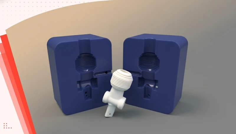
At the most fundamental level, an spuitgietvorm consists of two halves — the fixed (stationary) half and the moving half — mounted on the respective platens of the spuitgieten machine. When these two halves close, they create a sealed cavity that defines the shape of the final part. The fixed half typically contains the cavity (the concave side), while the moving half contains the core (the convex side).
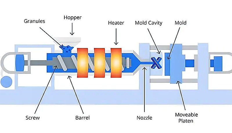
The mold base (also called the mold frame) is the structural foundation. It holds all the inserts, plates, and subsystems in precise alignment. Mold bases are usually made from medium-carbon steel such as P20 or S50C and must withstand thousands of tons of clamping force without deflecting. These components directly affect the stappen van spuitgieten and total productietijd spuitgieten, because filling, cooling, ejection, and inspection all depend on the tool layout.
“An injection mold contains multiple subsystems that must work in precise coordination.”Echt
The cavity, runner, cooling, ejection, guiding, venting, and support systems must all function together within tight tolerances — typically ±0.005 mm — for the mold to produce acceptable parts consistently.
“All injection molds use the same set of components regardless of part complexity.”Vals
Component selection varies widely: a simple single-cavity mold may use basic guide pins and straight-pull ejection, while a complex multi-cavity mold requires lifters, slides, hot runners, and sequential valve gates.
- Cavity and core inserts — the form-giving surfaces that define part geometry
- Runner system — channels that deliver molten plastic from the machine nozzle to the cavity
- Koelsysteem — water or oil channels that extract heat from the molded part
- Ejection system — pins, sleeves, and plates that push the part out after cooling
- Guiding system — leader pins and bushings that ensure mold halves align perfectly
- Venting system — shallow grooves that allow trapped air and gases to escape
- Support system — pillars, spacer blocks, and return pins that maintain structural rigidity
In practice, a production-class mold for a medium-complexity part might contain 50 to 200 individual components. A multi-cavity mold for something like a medical syringe barrel could have over 500 precision-machined parts. Each component must be manufactured to tight tolerances — often within ±0.005 mm — because any misalignment or dimensional drift shows up directly on the finished part.
In our factory in Shanghai, our team runs 47 injection molding machines ranging from 90T to 1850T, supported by an in-house mold manufacturing facility. Having tooling and production under one roof means we can iterate on mold components quickly — if an ejector pin1 needs repositioning or a cooling channel needs enlarging, the change happens on the same floor where the parts are being molded.
What Role Do the Cavity and Core Play in Mold Design?
The cavity and core are the heart of any injection mold — they are the surfaces that directly shape the plastic part. Get these right, and everything else becomes easier. Get them wrong, and no amount of process tuning will save the part.
De cavity is the concave (recessed) side of the mold that forms the external surfaces of the part. The core is the convex (protruding) side that forms the internal surfaces. When the mold closes, the gap between cavity and core defines the wall thickness and geometry of the molded part. This gap is the vormholte2 in the broader sense.
Material selection for cavity and core inserts is critical. For high-volume production (over 500,000 cycles), hardened tool steel such as H13, S136, or 8407 is standard. For shorter runs or prototypes, aluminum (such as 7075-T6) or P20 pre-hardened steel can reduce cost and lead time significantly. The surface finish of these inserts also transfers directly to the part — mirror-polished cavities produce glossy parts, while textured surfaces (applied via EDM or photo-etching) can hide flow marks and create grip patterns.
In practice, cavity and core design must account for material shrinkage. Every plastic material shrinks as it cools — typically 0.5% to 2.5% depending on the resin. The mold designer must scale the cavity dimensions by the expected shrinkage rate so that the final part meets specification after cooling. Getting this wrong means parts that are consistently oversized or undersized.
With experience across 400+ plastic materials, our engineers use MOLDFLOW simulation to predict shrinkage, weld-line positions, and air-trap locations before any steel is cut. Our team treats this upfront analysis as a tooling-risk check, especially for materials with high or anisotropic shrinkage rates, such as glass-filled nylon or fiber-reinforced PP.
How Does the Runner System Deliver Molten Plastic?
The runner system is the network of channels that transports molten plastic from the injection machine nozzle into the mold cavity. Its design directly affects fill balance, material waste, cycle time, and part quality.
A runner system has four main elements: the sprue (the main channel from the nozzle), the runners (distribution channels branching to each cavity), the gates (the narrow entry points into the cavity), and the cold slug wells (pockets that catch cooled material at the front of the melt stream). In multi-cavity molds, runner balance — ensuring each cavity fills at the same rate and pressure — is a fundamental design requirement.
There are two broad categories of runner systems. Koudlopersystemen are simpler and cheaper. The plastic in the channels solidifies with each cycle and is ejected as waste (or reground and reused). Hot runner systems use heated manifolds and nozzles to keep the plastic molten inside the mold, eliminating runner waste entirely. Hot runners add upfront cost but pay off quickly in high-volume production.
Gate design deserves special attention because the gate is where the melt enters the cavity and leaves a witness mark on the part. Common gate types include edge gates, submarine (tunnel) gates, pin-point gates, and valve gates. The choice depends on part geometry, aesthetic requirements, and whether gate vestige is acceptable on the visible surface.
In multi-cavity molds, achieving runner balance is essential for consistent part weight and dimensions across all cavities. Naturally balanced runners use equal-length paths from the sprue to each cavity, while artificially balanced runners adjust cross-section dimensions to equalize pressure drop. For high-precision parts with tight tolerances, even a 2-3% variation in fill time between cavities can produce measurable dimensional differences — which is why many production molds use valve-gated hot runner systems for positive shutoff and precise timing control.

“Hot runner systems eliminate runner waste by keeping plastic molten inside the mold.”Echt
Heated manifolds and nozzles maintain the polymer above its melting point throughout the feed system, so no solidified runner is produced — saving material and reducing post-processing.
“Runner design has no impact on part quality — only on material cost.”Vals
Runner layout and gate placement critically affect fill pattern, weld-line position, air traps, packing pressure, and dimensional consistency — all of which directly influence part quality.
Why Is the Cooling System Critical for Part Quality?
Cooling accounts for 60-70% of the total injection molding cycle time. A well-designed cooling system produces consistent parts faster; a poor one leads to warpage, sink marks, longer cycles, and higher per-part cost.
The cooling system consists of a network of channels drilled through the mold plates, typically carrying temperature-controlled water (or oil for high-temperature applications). These channels are positioned as close to the cavity surfaces as possible to extract heat efficiently. The layout must balance cooling uniformity against structural integrity — you cannot drill channels so close to the cavity that the mold cracks under injection pressure.
Traditional cooling uses straight, drilled channels, which work well for simple geometries. For complex parts with deep ribs or curved surfaces, conformal cooling3 channels — manufactured using metal 3D printing (DMLS/SLM) — follow the contour of the cavity surface. Studies have shown conformal cooling can reduce cycle time by 20-40% while improving dimensional consistency.
Cooling channel design also affects part aesthetics. Uneven cooling causes differential shrinkage, which shows up as warpage, sink marks on thick sections, or internal stress that leads to cracking later. Mold temperature must be matched to the material — running a mold too cold for a semi-crystalline material like nylon can cause premature freezing and incomplete fill.
The thermal conductivity of the mold steel itself also plays a role in cooling performance. Standard P20 steel has a thermal conductivity of about 30-35 W/(m·K), while beryllium copper inserts — sometimes used in hard-to-cool areas — offer 200+ W/(m·K), dramatically improving heat extraction. For molds running engineering resins that require higher mold temperatures (such as PEEK or LCP), oil-heated thermal regulators maintain mold temperature at 150-200°C rather than using water cooling.
In multi-cavity molds, cooling balance between cavities is just as important as the absolute cooling rate. If one cavity cools faster than its neighbors, the resulting dimensional variation between parts from the same shot can be significant enough to reject some cavities outright. Flow regulators or restrictors in the cooling circuit help equalize water distribution across all cavities, ensuring consistent part quality from every cavity in the mold.
“Cooling time accounts for 60-70% of the total injection molding cycle.”Echt
After the cavity is filled, the part must cool below its ejection temperature before the mold can open. This waiting period dominates cycle time, making cooling optimization the most effective lever for productivity.
“All cooling channels must be perfectly straight drilled holes.”Vals
While traditional drilling produces straight channels, conformal cooling channels made via metal 3D printing can follow curved cavity surfaces, providing far more uniform cooling for complex geometries.
The relationship between cooling channel diameter and flow rate is also important. Larger diameter channels (10-14 mm) allow higher flow rates and better heat removal but remove more steel from the mold, potentially weakening the structure. Smaller channels (6-8 mm) maintain structural integrity but require higher pressure to achieve adequate flow. Most production molds use 8-10 mm channels as a practical compromise, with baffles or inserts to direct flow precisely where it is needed most.
Baffle design inside cooling channels also matters. Straight-through channels are the simplest, but baffled channels — where a blade redirects flow to make a U-turn inside the channel — provide better heat transfer by forcing water against the cavity surface. For cores and slender features, spiral cooling channels or bubbler tubes deliver water deep into the feature and back out again, preventing hot spots that cause differential shrinkage and warpage.
How Does the Ejection System Remove Finished Parts?
This section is about es the ejection system remove finished parts and its impact on cost, quality, timing, or sourcing risk. Once the plastic part has cooled sufficiently, it must be cleanly removed from the mold. The ejection system handles this critical step, and its design determines whether parts come out cleanly, consistently, and without cosmetic damage.
The core ejection components include ejector pins (straight round pins that push on the part), ejector sleeves (hollow pins that push around a core pin), stripper plates (full-face plates that strip the entire part off the core), and lifters (angled mechanisms that form and release undercuts). These are driven by an ejector plate that moves as a unit, actuated by the injection machine’s hydraulic or mechanical ejection system.
Ejector pin placement is a careful balance. Too few pins, and the part distorts or cracks during ejection. Too many pins, and you leave excessive witness marks on the part surface. The pins must push on areas of the part that are structurally rigid — ribs, bosses, or thick wall sections — rather than on thin walls that would deform.
For parts with undercuts (features that cannot be released in a straight pull), the mold needs side-action mechanisms: lifters for internal undercuts and slides for external undercuts. These add significant complexity and cost to the mold but are essential for features like snap fits, thread profiles, or lateral holes.
What Are the Guiding and Positioning Components?
Precision alignment between the two mold halves is non-negotiable. Even a few thousandths of a millimeter of misalignment creates flash (thin unwanted material at the parting line), mismatched wall thickness, or dimensional failure on the molded part.
De primaire geleidende componenten zijn leidingspennen (ook wel geleidingspennen genoemd) en geleidingsbussen. Leidingspennen zijn gemonteerd op één matrijshellft (meestal de bewegende kant) en komen in de overeenkomstige geleidingsbussen aan de tegenoverliggende kant terecht wanneer de matrijs sluit. Ze grijpen in voordat de holte-oppervlakken elkaar raken, waardoor de twee helften zijn uitgelijnd voordat ze de volledige klemkracht dragen.
Voor hogere precisie gebruiken matrijzen ook conische vergrendelingen (ook wel centeerringen of uitlijnvergrendelingen genoemd). Dit zijn conische mannelijk-vrouwelijke paren die in de holte- en kerninzetstukken zijn gefreesd en die een definitieve, strakke uitlijning op de scheidingslijn bieden. Rechte leidingspennen zorgen voor grove uitlijning; vergrendelingen zorgen voor de laatste paar micron.
In meerplaatsmatrijzen (zoals stripperplaat- of drieplaatmatrijzen) zijn extra geleidingspensets nodig om elk platenpaar uit te lijnen. Positioneringspennen (dowelpennen) worden ook door de hele matrijs gebruikt om te zorgen dat inzetstukken in hun juiste positie zijn vergrendeld en niet kunnen draaien of verschuiven onder injectiedruk.
Welke Hulpcomponenten Verbeteren de Matrijsprestaties?
Dit gedeelte gaat over hulpcomponenten die de matrijsprestaties verbeteren en hun impact op kosten, kwaliteit, timing of inkooprisico. Naast de belangrijkste subsystemen dragen diverse hulpcomponenten bij aan de betrouwbaarheid, levensduur en prestaties van de matrijs. Dit zijn de onderdelen die zelden aandacht krijgen — totdat ze falen.
Ontluchtingsgroeven zijn ondiepe kanalen (meestal 0,01-0,03 mm diep) die in het scheidingsoppervlak zijn geslepen en die ingesloten lucht en ontbindingsgassen laten ontsnappen vóór het oprukkende smeltfront. Zonder adequate ontluchting comprimeert en verhit de ingesloten lucht tot het punt van dieselmotorontsteking — een fenomeen dat gasverbranding of dieselen wordt genoemd en dat het kunststofoppervlak verkoolt.
Veren (terugslagveren, stripperveren) zorgen voor de terugslagkracht voor uitwerp- of stripperplaten en voorspanning voor schuifmechanismen. Schijfveren komen veel voor bij toepassingen met hoge krachten, terwijl spiraalveren lichtere taken uitvoeren. Vermoeidheid van veren is een veelvoorkomend onderhoudspunt — veren verliezen na verloop van tijd kracht, wat uitwerpproblemen of onvolledige schuifterugslag veroorzaakt.
Afdichtingen en O-ringen voorkom koelvloeistoflekken op kanaalkruisingen en pluginterfaces. Een koelvloeistoflek in de matrijs is een ernstig probleem — het veroorzaakt roest, verontreinigt onderdelen en kan verwarmingscircuits in heetkanaalmatrijzen kortsluiten. O-ringmateriaal moet compatibel zijn met de temperatuur en chemie van de koelvloeistof (EPDM voor water, fluorkoolstof voor hoge-temperatuur olie).
“Ontluchtingsgroeven die te ondiep zijn, houden lucht vast en veroorzaken gasverbrandingen op het onderdeel.”Echt
Wanneer de ontluchtingsdiepte onvoldoende is, bereikt samengeperste lucht de ontstekingstemperatuur en veroorzaakt het diesel-effect — het verkolen van het kunststofoppervlak met zichtbare brandvlekken aan het einde van de vulling.
“O-ringen in koelsystemen hoeven nooit vervangen te worden als ze correct geïnstalleerd zijn.”Vals
O-ringen degraderen door thermische cycli, blootstelling aan chemicaliën en mechanische drukvervorming. De meeste fabrikanten raden aan om koelvloeistof O-ringen elke 6-12 maanden te vervangen als onderdeel van preventief onderhoud.
Steunpilaren (ook wel steunkolommen genoemd) bevinden zich tussen de B-plaat en de steunplaat van de bewegende matrijshellft. Ze voorkomen dat de B-plaat doorbuigt onder de injectiedruk. Zonder voldoende steun buigt de plaat door, opent de scheidingslijn en ontstaat er uitvulling. Het aantal en de diameter van de steunkolommen worden berekend op basis van het geprojecteerde holte-oppervlak en de piek-injectiedruk.
Andere hulpcomponenten zijn onder meer verwarmingsbanden en thermokoppels (voor temperatuurregeling van het heetkanaalsysteem), slijtplaten (vervangbare oppervlakken die wrijving door glijden absorberen), kettingpoelies en eindschakelaars (voor sequentiële schuifbeweging).
Het onderhouden van meer dan 100 matrijsets per maand betekent dat ons gereedschapsteam dagelijks slijtage van hulpcomponenten behandelt. Ventielreiniging, veervervanging en O-ringwissels maken deel uit van ons standaard preventief onderhoudsprotocol — niet iets dat wacht op een storing.
Hoe worden spuitgietmatrijzen ontworpen en vervaardigd?
Dit gedeelte gaat over spuitgietmatrijzen die worden ontworpen en vervaardigd en hun impact op kosten, kwaliteit, timing of inkooprisico. Het bouwen van een productieklasse spuitgietmatrijs is een meerdaags technisch project dat software-simulatie, precisiebewerking, warmtebehandeling en handafwerking combineert. Inzicht in dit proces helpt u matrijsoffertes, tijdlijnen en kwaliteit te evalueren.
Het proces begint met onderdeelontwerpbeoordeling en DFM (Ontwerp voor Maakbaarheid). De matrijsontwerper analyseert de onderdeelgeometrie op kenmerken die het spuitgieten bemoeilijken — ondervormen, ongelijke wanddikte, diepe ribben, strakke toleranties — en beveelt aanpassingen aan voordat er staal wordt gesneden. Dit is waar de meest kosteneffectieve beslissingen worden genomen.
Vervolgens komen matrijzenstromsimulatie met software zoals MOLDFLOW of Moldex3D. De simulatie voorspelt het vulpatroon, laslijnlocaties, luchtinsluitingen, krimp en koelrendement. De ontwerper past poortlocaties, loopkanaaldimensies en koelopstelling aan op basis van de simulatieresultaten. Een goede simulatie bespaart weken aan trial-and-error tijdens de matrijsinbedrijfstelling.
Na simulatie, de matrijsontwerp is definitief vastgelegd in CAD (UG/NX, SOLIDWORKS, of soortgelijke). Elk component — inserts, pinnen, bushings, veerkracht, O-ringen — wordt gedetailleerd met dimensies, toleranties en materiaalspecificaties. Het voltooide ontwerppakket bevat assemblage-tekeningen, individuele deeltekeningen en een materiaallijst.
“Matrijssimulatie kan vulpatronen en defectlocaties voorspellen voordat er staal wordt gesneden.”Echt
Software zoals MOLDFLOW en Moldex3D simuleert het injectieproces digitaal, waardoor ontwerpers poortlocaties, loopkanaaldimensies en koelopstelling kunnen optimaliseren — wat weken aan fysieke trial-and-error bespaart.
“Een productiematrijzen hoeft slechts één proefrun te ondergaan voordat het gereed is voor massaproductie.”Vals
Productiematrijzen doorlopen doorgaans 2-4 proefiteraties om de poortgrootte, ontluchtingsdiepte, koelbalans en uitwerptiming te verfijnen. Elke proef produceert monsters die worden gemeten en geëvalueerd, waarbij staalaanpassingen tussen de runs worden uitgevoerd.
| Matrijzenproductiestap | Belangrijk proces | Typical Tolerance |
|---|---|---|
| CNC-frezen | 3-5 axis machining van holte/kern blokken | ±0,005 mm |
| EDM (Sinker) | Uitbranden van diepe ribben en scherpe hoeken | ±0,01 mm |
| Wire EDM | Doorlopende profielen voor lifters en inzetstukken | ±0,005 mm |
| Oppervlakte Grinding | Voorbereiding van vlakke scheidingsvlakken | ±0,002 mm |
| Polijsten | Spiegel, SPI A-1 tot A-3 afwerking | Ra 0,012–0,025 μm |
Machinale bewerking omvat CNC-frezen (voor holte/kernblokken en matrijshouder), EDM (Electrical Discharge Machining voor fijne details en scherpe hoeken die snijders niet kunnen bereiken), draad-EDM (voor doorlopende profielen zoals schuine liften), oppervlakteslijpen (voor vlakke scheidingsvlakken), en polijsten (voor spiegel- of gespecificeerde oppervlakteafwerkingen). Geharde inserts kunnen meerdere warmtebehandelingscycli doorlopen tijdens de machining om stress te verlichten en de doelhardheid te bereiken (typisch 48-52 HRC voor P20, 50-54 HRC voor H13).
Ten slotte wordt de matrijs geassembleerd, getest en gekwalificeerd tot T1 (eerste proef) steekproeven. De T1-steekproeven worden gemeten aan de hand van onderdeeltekeningen, en eventueel benodigde staalaanpassingen (toevoegen van ontluchtingskanalen, aanpassen van de poortgrootte, polijsten van plakkerige gebieden) worden uitgevoerd. Een productiematrijs doorloopt doorgaans 2-4 proefiteraties voordat deze wordt vrijgegeven voor productie.
Met meer dan 20 jaar ervaring in het bouwen van matrijzen onder ISO 9001, ISO 13485, ISO 14001 en ISO 45001 systemen, is ons proces gestandaardiseerd van DFM-beoordeling tot T1-steekproeven. Elke matrijs doorloopt gedocumenteerde kwaliteitscontroles — verificatie van staalhardheid, dimensionale inspectie van inzetstukken en minimaal twee proefruns voordat we verzenden of de productie starten.

Veelgestelde vragen over spuitgietmatrijzencomponenten?
Wat is het verschil tussen een holte en een kern in een spuitgietmatrijs?
De holte is de concave (ingesprongen) zijde van de matrijs die de externe oppervlakken van het product vormt, terwijl de kern de convex (uitstekende) zijde is die de interne oppervlakken vormt. Samen definiëren ze de volledige geometrie van het gegoten product, waarbij de opening tussen hen de wanddikte bepaalt. In de praktijk bevindt de holte zich meestal op de vaste (stationaire) matrijshelft en de kern op de beweegbare helft, maar dit kan variëren afhankelijk van de productgeometrie en ejectiestrategie. Het begrip van het verschil tussen deze twee componenten is essentiaal bij het specificeren van matrijsvereisten, het reviewen van DFM-feedback, of het oplossen van flash- en dimensionale problemen tijdens de productie.
Uit hoeveel componenten bestaat een typische spuitgietmatrijs?
Een standaard productiematrijs voor één holte bevat meestal 50 tot 200 individuele componenten, inclusief holte- en kerninserts, ejectorstiften, geleidingsstiften, koelplaatjes, veerringen en O-ringen. Matrijzen met meerdere holtes of met complexe zijacties kunnen 500 of meer precisieonderdelen bevatten. Elk component moet worden vervaardigd met nauwe toleranties, vaak binnen 0,005 mm, om een consistente kwaliteit van het product te garanderen over duizenden productiecycli. Bij het evalueren van matrijs-offertes helpt het begrip van dit aantal componenten om te beoordelen of een leverancier een adequate complexiteit van de gereedschappen voorstelt of cruciale subsystemen zoals koeling en ejectie afkort.
Welk materiaal wordt gebruikt voor spuitgietmatrijscomponenten?
Holte- en kerninserts worden typisch gemaakt van gehard gereedschapstaal zoals H13, S136, P20, of 8407 voor matrijzen voor hoogvolume productie. Matrijsbases gebruiken medium-carbon staal zoals S50C. Ejectorstiften worden gemaakt van gehard SUJ2 draagstaal voor slijtvastheid. Voor prototype- of low-volume matrijzen kunnen aluminiumlegeringen zoals 7075-T6 de kosten en levertijd reduceren door 30-50%. De keuze van materiaal hangt af van productievolume, abrasiviteit van het kunststof, vereiste oppervlakteafwerking, en budgetbeperkingen. Uw matrijsleverancier zou specifieke kwaliteiten moeten aanbevelen op basis van uw applicatie, in plaats van een standaard 'one-size-fits-all' staalselectie.
Waarom hebben spuitgietmatrijzen koelkanalen nodig?
Koelkanalen circuleren temperatuurgecontroleerd water of olie door de matrijs om warmte te verwijderen van het stollende plastic product. Omdat koeling 60-70% van de totale spuitgietcyclustijd vertegenwoordigt, is efficiënte kanaaldesign de meest effectieve manier om productieoutput te verhogen en per-product kosten te reduceren. Proper koeling voorkomt ook common defects zoals warpage, sink marks op dikke secties, en interne reststress door te zorgen dat het product uniform stolt voor ejectie. Het overslaan van koelingoptimalisatie tijdens matrijsdesign is één van de meest kostbare mistakes die je kunt maken in gereedschapsprocurement.
Wat is het doel van uitwerppennen in een spuitgietmatrijs?
Uitwerppennen zijn geharde stalen staven die het afgekoelde en gestolde onderdeel uit de matrijsholte duwen nadat de matrijs opent. Ze zijn gemonteerd op een uitwerpplaat die wordt bediend door het hydraulische of mechanische uitwerpsysteem van de spuitgietmachine. Het aantal pennen, de diameter en de plaatsing moeten zorgvuldig worden ontworpen om een uniforme uitwerpkracht toe te passen zonder het onderdeel te vervormen of zichtbare sporen achter te laten op oppervlakken. Typische diameters variëren van 2 mm tot 12 mm, afhankelijk van de grootte van het onderdeel, en pennen moeten duwen op structureel stijve kenmerken zoals ribben of bussen in plaats van dunne wandgedeelten.
Het begrip van spuitgietmatrijscomponenten heeft direct effect op uw ability om de juiste matrijs te specificeren, leverancier-offertes te evalueren, en productieproblemen te troubleshooten.
-
uitwerppen: Een uitwerppen is een geharde stalen staaf die het gegoten onderdeel na afkoeling uit de holte duwt, aangedreven door het uitwerpsysteem van de spuitgietmachine. ↩
-
mold cavity: matrijsholte verwijst naar een matrijsholte is de holle ruimte binnen een matrijs die de externe vorm en oppervlakteafwerking van het gegoten product definieert. ↩
-
conformal cooling: conforme koeling verwijst naar kanalen die de contouren van de matrijsholte volgen, waardoor een meer uniforme koeling wordt verkregen en de cyclustijd wordt verminderd in vergelijking met traditionele geboorde kanalen. ↩


