 Zum Inhalt springen

Spritzgusswerkzeuge sind das Rückgrat der modernen Kunststofffertigung. Ob Sie einen einfachen Flaschenverschluss oder ein komplexes Automobilgehäuse spritzen, das Werkzeug selbst ist eine Präzisionsbaugruppe aus Dutzenden – manchmal Hunderten – von Einzelkomponenten, die jeweils einen bestimmten Zweck erfüllen.
Eine Spritzgussform umfasst typischerweise den Formengrundkörper, Kavitäten- und Kerneinsätze, ein Angusssystem (Anguss, Läufer, Anschnitte), Kühlkanäle, Auswerferstifte und -platten, Führungsstifte und -buchsen, Entlüftungsnuten, Stützsäulen sowie verschiedene Hilfskomponenten wie Federn, Dichtungen und Schieber – alles konstruiert, um Kunststoffteile mit wiederholbarer Präzision zu formen, zu kühlen und auszuwerfen.
Diese Anleitung zerlegt jede wichtige Komponentengruppe, erklärt die Funktion jedes Teils und teilt praktische Einblicke aus zwei Jahrzehnten Bau und Betrieb von Spritzgießformen in unserem Shanghai Werk. Wenn Sie eine neue Form entwerfen oder eine bestehende analysieren, ist das Verständnis dieser Komponenten der Startpunkt für gute Entscheidungen.
- Eine Spritzgießform hat 8+ Komponentengruppen: Kavität/Kern, Anguss, Kühlung, Ausstoß, Führung, Entlüftung, Unterstützung und Hilfsysteme
- Kavität und Kern definieren die Bauteilform – ihr Material und ihre Oberfläche beeinflussen direkt die Bauteilqualität
- Das Angussdesign (heiß vs. kalt) beeinflusst Materialverschwendung, Zykluszeit und Produktionskosten
- Kühlkanäle steuern Zykluszeit und Bauteilverzug – konforme Kühlung kann Zyklen um 20–40% reduzieren
- Ausstoßstifttyp, Anzahl und Platzierung bestimmen, ob Teile sauber oder mit Beschädigung freigesetzt werden

Was sind die Kernkomponenten eines Spritzgusswerkzeugs?
Jede Spritzgießform, unabhängig von der Komplexität, teilt einen gemeinsamen Satz von Kernkomponenten, die zusammenarbeiten, um Kunststoffteile zu formen, zu kühlen und auszustossen. Das Verständnis dieser Bausteine ist essentiell für jeden, der in Formdesign involviert ist, Beschaffung eines Spritzgießlieferanten, oder Produktion.
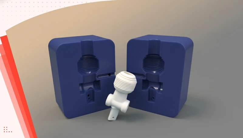
Auf grundlegendster Ebene ist eine Spritzgussform besteht aus zwei Hälften – der feststehenden Hälfte und der beweglichen Hälfte – die auf den jeweiligen Platten des Spritzgießen Maschine. Wenn diese beiden Hälften schließen, bilden sie eine geschlossene Kavität, die die Form des Endteils definiert. Die feste Hälfte umfasst typisch die Kavität (die konkave Seite), während die mobile Hälfte den Kern (die konvexe Seite) umfasst.
Der Formengrundkörper (auch Formrahmen genannt) ist die strukturelle Grundlage. Er hält alle Einsätze, Platten und Subsysteme in präziser Ausrichtung. Formengrundkörper bestehen üblicherweise aus mittellegiertem Stahl wie P20 oder S50C und müssen Tausende Tonnen Schließkraft ohne Verformung aushalten. Diese Komponenten beeinflussen direkt die Schritte des Spritzgießens und insgesamt Produktionszeit beim Spritzgießen, da Füllen, Kühlen, Auswerfen und Kontrolle alle vom Werkzeuglayout abhängen.
„Eine Spritzgießform enthält mehrere Subsysteme, die in präziser Koordination arbeiten müssen.“Wahr
Die Kavität, der Anguss, die Kühlung, das Auswerfen, die Führung, die Entlüftung und die Stützsysteme müssen alle innerhalb enger Toleranzen – typischerweise ±0,005 mm – zusammenarbeiten, damit das Werkzeug konsistent akzeptable Teile produziert.
„Alle Spritzgussformen verwenden denselben Satz von Komponenten, unabhängig von der Bauteilkomplexität.“Falsch
Die Komponentenauswahl variiert stark: Ein einfaches Einfachkavitätswerkzeug kann grundlegende Führungsstifte und geradlinige Auswerfer verwenden, während ein komplexes Mehrfachkavitätswerkzeug Lifter, Schieber, Heißkanäle und sequentielle Ventiltore erfordert.
- Kavitäten- und Kerneinsätze — die formgebenden Flächen, die die Bauteilgeometrie definieren
- Angusssystem — Kanäle, die geschmolzenes Kunststoff vom Maschinendüse zur Kavität liefern
- Das Kühlsystem — Wasser- oder Ölkanäle, die Wärme aus dem geformten Teil abführen
- Ejection system — Stifte, Hülsen und Platten, die das Teil nach dem Kühlen herausdrücken
- Führungssystem — Führungsstifte und Buchsen, die eine perfekte Ausrichtung der Formhälften sicherstellen
- Entlüftungssystem — flache Nuten, die eingeschlossene Luft und Gase entweichen lassen
- Stützsystem – Säulen, Abstandshalter und Rückholstifte, die die strukturelle Steifigkeit aufrechterhalten
In der Praxis könnte eine Produktionsklasse-Form für ein mittelkomplexes Teil 50 bis 200 einzelne Komponenten enthalten. Eine Mehrkavitäten-Form für etwas wie eine medizinische Spritzenhülse könnte über 500 präzisionsbearbeitete Teile haben. Jede Komponente muss mit engen Toleranzen gefertigt werden — oft innerhalb ±0,005 mm — weil jede Fehlausrichtung oder dimensionale Abweichung direkt auf dem fertigen Teil sichtbar wird.
In unserem Werk in Shanghai betreibt unser Team 47 Spritzgießmaschinen von 90T bis 1850T, unterstützt durch eine eigene Formenbaufertigung. Werkzeugbau und Produktion unter einem Dach bedeutet, dass wir schnell an Formenkomponenten iterieren können – wenn ein Ausstoßstift1 muss neu positioniert werden oder ein Kühlkanal muss vergrößert werden, die Veränderung erfolgt auf der gleichen Ebene, wo die Teile geformt werden.
Welche Rolle spielen Kavität und Kern im Formenbau?
Die Kavität und der Kern sind das Herzstück jedes Spritzgusswerkzeugs – sie sind die Oberflächen, die das Kunststoffteil direkt formen. Wenn diese richtig sind, wird alles andere einfacher. Wenn sie falsch sind, wird keine Prozessoptimierung das Teil retten.
Die Kavität ist die konkave (vertiefte) Seite des Werkzeugs, die die äußeren Oberflächen des Teils bildet. Die Kern is the convex (protruding) side that forms the internal surfaces. When the mold closes, the gap between cavity and core defines the wall thickness and geometry of the molded part. This gap is the Formhohlraum2 in the broader sense.
Material selection for cavity and core inserts is critical. For high-volume production (over 500,000 cycles), hardened tool steel such as H13, S136, or 8407 is standard. For shorter runs or prototypes, aluminum (such as 7075-T6) or P20 pre-hardened steel can reduce cost and lead time significantly. The surface finish of these inserts also transfers directly to the part — mirror-polished cavities produce glossy parts, while textured surfaces (applied via EDM or photo-etching) can hide flow marks and create grip patterns.
In practice, cavity and core design must account for material shrinkage. Every plastic material shrinks as it cools — typically 0.5% to 2.5% depending on the resin. The mold designer must scale the cavity dimensions by the expected shrinkage rate so that the final part meets specification after cooling. Getting this wrong means parts that are consistently oversized or undersized.
With experience across 400+ plastic materials, our engineers use MOLDFLOW simulation to predict shrinkage, weld-line positions, and air-trap locations before any steel is cut. Our team treats this upfront analysis as a tooling-risk check, especially for materials with high or anisotropic shrinkage rates, such as glass-filled nylon or fiber-reinforced PP.
Wie liefert das Angussystem geschmolzenes Kunststoff?
The runner system is the network of channels that transports molten plastic from the injection machine nozzle into the mold cavity. Its design directly affects fill balance, material waste, cycle time, and part quality.
A runner system has four main elements: the sprue (the main channel from the nozzle), the runners (distribution channels branching to each cavity), the gates (the narrow entry points into the cavity), and the cold slug wells (pockets that catch cooled material at the front of the melt stream). In multi-cavity molds, runner balance — ensuring each cavity fills at the same rate and pressure — is a fundamental design requirement.
There are two broad categories of runner systems. Kaltkanalsysteme are simpler and cheaper. The plastic in the channels solidifies with each cycle and is ejected as waste (or reground and reused). Hot runner systems use heated manifolds and nozzles to keep the plastic molten inside the mold, eliminating runner waste entirely. Hot runners add upfront cost but pay off quickly in high-volume production.
Gate design deserves special attention because the gate is where the melt enters the cavity and leaves a witness mark on the part. Common gate types include edge gates, submarine (tunnel) gates, pin-point gates, and valve gates. The choice depends on part geometry, aesthetic requirements, and whether gate vestige is acceptable on the visible surface.
In multi-cavity molds, achieving runner balance is essential for consistent part weight and dimensions across all cavities. Naturally balanced runners use equal-length paths from the sprue to each cavity, while artificially balanced runners adjust cross-section dimensions to equalize pressure drop. For high-precision parts with tight tolerances, even a 2-3% variation in fill time between cavities can produce measurable dimensional differences — which is why many production molds use valve-gated hot runner systems for positive shutoff and precise timing control.

“Hot runner systems eliminate runner waste by keeping plastic molten inside the mold.”Wahr
Heated manifolds and nozzles maintain the polymer above its melting point throughout the feed system, so no solidified runner is produced — saving material and reducing post-processing.
“Runner design has no impact on part quality — only on material cost.”Falsch
Runner layout and gate placement critically affect fill pattern, weld-line position, air traps, packing pressure, and dimensional consistency — all of which directly influence part quality.
Warum ist das Kühlsystem für die Bauteilqualität entscheidend?
Cooling accounts for 60-70% of the total injection molding cycle time. A well-designed cooling system produces consistent parts faster; a poor one leads to warpage, sink marks, longer cycles, and higher per-part cost.
The cooling system consists of a network of channels drilled through the mold plates, typically carrying temperature-controlled water (or oil for high-temperature applications). These channels are positioned as close to the cavity surfaces as possible to extract heat efficiently. The layout must balance cooling uniformity against structural integrity — you cannot drill channels so close to the cavity that the mold cracks under injection pressure.
Traditional cooling uses straight, drilled channels, which work well for simple geometries. For complex parts with deep ribs or curved surfaces, conformal cooling3 channels — manufactured using metal 3D printing (DMLS/SLM) — follow the contour of the cavity surface. Studies have shown conformal cooling can reduce cycle time by 20-40% while improving dimensional consistency.
Cooling channel design also affects part aesthetics. Uneven cooling causes differential shrinkage, which shows up as warpage, sink marks on thick sections, or internal stress that leads to cracking later. Mold temperature must be matched to the material — running a mold too cold for a semi-crystalline material like nylon can cause premature freezing and incomplete fill.
The thermal conductivity of the mold steel itself also plays a role in cooling performance. Standard P20 steel has a thermal conductivity of about 30-35 W/(m·K), while beryllium copper inserts — sometimes used in hard-to-cool areas — offer 200+ W/(m·K), dramatically improving heat extraction. For molds running engineering resins that require higher mold temperatures (such as PEEK or LCP), oil-heated thermal regulators maintain mold temperature at 150-200°C rather than using water cooling.
In multi-cavity molds, cooling balance between cavities is just as important as the absolute cooling rate. If one cavity cools faster than its neighbors, the resulting dimensional variation between parts from the same shot can be significant enough to reject some cavities outright. Flow regulators or restrictors in the cooling circuit help equalize water distribution across all cavities, ensuring consistent part quality from every cavity in the mold.
“Cooling time accounts for 60-70% of the total injection molding cycle.”Wahr
After the cavity is filled, the part must cool below its ejection temperature before the mold can open. This waiting period dominates cycle time, making cooling optimization the most effective lever for productivity.
“All cooling channels must be perfectly straight drilled holes.”Falsch
While traditional drilling produces straight channels, conformal cooling channels made via metal 3D printing can follow curved cavity surfaces, providing far more uniform cooling for complex geometries.
The relationship between cooling channel diameter and flow rate is also important. Larger diameter channels (10-14 mm) allow higher flow rates and better heat removal but remove more steel from the mold, potentially weakening the structure. Smaller channels (6-8 mm) maintain structural integrity but require higher pressure to achieve adequate flow. Most production molds use 8-10 mm channels as a practical compromise, with baffles or inserts to direct flow precisely where it is needed most.
Baffle design inside cooling channels also matters. Straight-through channels are the simplest, but baffled channels — where a blade redirects flow to make a U-turn inside the channel — provide better heat transfer by forcing water against the cavity surface. For cores and slender features, spiral cooling channels or bubbler tubes deliver water deep into the feature and back out again, preventing hot spots that cause differential shrinkage and warpage.
Wie entfernt das Auswurfsystem fertige Teile?
This section is about es the ejection system remove finished parts and its impact on cost, quality, timing, or sourcing risk. Once the plastic part has cooled sufficiently, it must be cleanly removed from the mold. The ejection system handles this critical step, and its design determines whether parts come out cleanly, consistently, and without cosmetic damage.
The core ejection components include ejector pins (straight round pins that push on the part), ejector sleeves (hollow pins that push around a core pin), Abstreifplatten (full-face plates that strip the entire part off the core), and lifters (angled mechanisms that form and release undercuts). These are driven by an ejector plate that moves as a unit, actuated by the injection machine’s hydraulic or mechanical ejection system.
Ejector pin placement is a careful balance. Too few pins, and the part distorts or cracks during ejection. Too many pins, and you leave excessive witness marks on the part surface. The pins must push on areas of the part that are structurally rigid — ribs, bosses, or thick wall sections — rather than on thin walls that would deform.
For parts with undercuts (features that cannot be released in a straight pull), the mold needs side-action mechanisms: lifters for internal undercuts and slides für externe Hinterschneidungen. Diese erhöhen die Komplexität und Kosten der Form erheblich, sind aber für Merkmale wie Schnappverbindungen, Gewindeprofile oder seitliche Löcher unerlässlich.
Was sind die Führungs- und Positionierungskomponenten?
Die präzise Ausrichtung zwischen den beiden Werkzeughälften ist nicht verhandelbar. Selbst wenige Tausendstel Millimeter Fehlausrichtung verursachen Grat (dünnes, unerwünschtes Material an der Trennlinie), ungleichmäßige Wandstärken oder Maßabweichungen am geformten Teil.
Die primären Führungskomponenten sind Führungsstifte (auch als Führungsstifte bezeichnet) und Führungsbuchsen. Führungsstifte sind auf einer Formhälfte montiert (typischerweise die bewegliche Seite) und treten beim Schließen der Form in entsprechende Führungsbuchsen auf der gegenüberliegenden Hälfte ein. Sie greifen ein, bevor die Kavitätenoberflächen sich berühren, und stellen sicher, dass beide Hälften ausgerichtet sind, bevor sie die volle Schließkraft aufnehmen.
Für höhere Präzision verwenden Formen auch konische Verriegelungen (auch als Zentrierringe oder Ausrichtsverriegelungen bezeichnet). Dies sind konische männlich-weibliche Paare, die in den Kavitäten- und Kern-Einsätzen bearbeitet sind und eine endgültige, präzise Ausrichtung an der Teilungslinie bieten. Gerade Führungsstifte sorgen für die Grobausrichtung; Verriegelungen handhaben die letzten paar Mikrometer.
Bei Mehrplattenwerkzeugen (wie Abstreifplatten- oder Dreiplattenwerkzeugen) sind zusätzliche Führungsstifte erforderlich, um jedes Plattenpaar auszurichten. Positionierungsstifte (Passstifte) werden auch im gesamten Werkzeug verwendet, um sicherzustellen, dass Einsätze in ihrer korrekten Position verriegelt sind und sich unter Spritzdruck nicht drehen oder verschieben können.
Welche Hilfskomponenten verbessern die Formleistung?
Dieser Abschnitt handelt davon, wie Hilfskomponenten die Formleistung verbessern und deren Auswirkungen auf Kosten, Qualität, Zeitplan oder Beschaffungsrisiko. Neben den Hauptsubsystemen trägt eine Reihe von Hilfskomponenten zur Formzuverlässigkeit, Langlebigkeit und Leistung bei. Dies sind die Teile, die selten Aufmerksamkeit erhalten – bis sie versagen.
Entlüftungsnuten sind flache Kanäle (typischerweise 0,01-0,03 mm tief), die in die Trennfläche eingearbeitet sind und eingeschlossene Luft und Zersetzungsgase vor der fortschreitenden Schmelzfront entweichen lassen. Ohne ausreichende Entlüftung komprimiert sich die eingeschlossene Luft und erhitzt sich bis zum Punkt der Dieselzündung – ein Phänomen, das als Gasbrand oder Dieseln bezeichnet wird und die Kunststoffoberfläche verkohlt.
Federn (Rückholfedern, Abstreiffedern) liefern die Rückstellkraft für Auswerferplatten und Vorspannung für Schiebermechanismen. Tellerfedern sind bei Hochkraftanwendungen üblich, während Schraubenfedern leichtere Aufgaben übernehmen. Federermüdung ist ein häufiger Wartungspunkt – Federn verlieren mit der Zeit an Kraft, was zu Auswerferproblemen oder unvollständigem Schieberrücklauf führt.
Dichtungen und O-Ringe verhindern Sie Kühlmittellecks an Kanalübergängen und Stopfen-Schnittstellen. Ein Kühlmittelleck in der Form ist ein ernstes Problem – es verursacht Rost, kontaminiert Teile und kann Heizkreise in Heißkanalformen kurzschließen. Das O-Ring-Material muss mit der Kühlmitteltemperatur und -chemie kompatibel sein (EPDM für Wasser, Fluorkohlenstoff für Hochtemperaturöl).
„Zu flache Entlüftungsnuten halten Luft zurück und verursachen Gasbrandflecken am Teil.“Wahr
Wenn die Entlüftungstiefe unzureichend ist, erreicht Druckluft die Zündtemperatur und verursacht den Diesel-Effekt – die Kunststoffoberfläche verkohlt mit sichtbaren Brandflecken am Ende der Füllung.
„O-Ringe in Kühlsystemen müssen bei korrekter Installation nie ausgetauscht werden.“Falsch
O-Ringe verschleißen durch thermische Zyklen, chemische Einwirkung und mechanische Druckverformung. Die meisten Hersteller empfehlen, Kühlmittel-O-Ringe alle 6-12 Monate im Rahmen der vorbeugenden Wartung auszutauschen.
Stützpfeiler (auch als Stützsäulen bezeichnet) sitzen zwischen der B-Platte und der Stützplatte der beweglichen Formhälfte. Sie verhindern, dass sich die B-Platte unter dem Einspritzdruck verformt. Ohne ausreichende Stützung wölbt sich die Platte, die Teilungslinie öffnet sich und es entstehen Grat. Anzahl und Durchmesser der Stützpfeiler werden basierend auf der projizierten Kavitätenfläche und dem maximalen Einspritzdruck berechnet.
Andere Hilfskomponenten umfassen Heizbänder und Thermoelemente (für Heißkanal-Temperaturregelung), Verschleißplatten (austauschbare Oberflächen, die Gleitreibung absorbieren), Kettenrollen und Endschalter (für sequenzielle Schiebebewegung).
Die Wartung von über 100 Formensätzen pro Monat bedeutet, dass unser Werkzeugteam täglich mit dem Verschleiß von Hilfskomponenten umgeht. Entlüftungsreinigung, Federersatz und O-Ring-Tausch sind Teil unseres standardmäßigen vorbeugenden Wartungsprotokolls – nicht etwas, das auf einen Ausfall wartet.
Wie werden Spritzgussformen konstruiert und hergestellt?
Dieser Abschnitt handelt von entworfenen und hergestellten Spritzgießformen und deren Auswirkungen auf Kosten, Qualität, Zeitplan oder Beschaffungsrisiko. Der Bau einer produktionsreifen Spritzgießform ist ein mehrwöchiges Ingenieursprojekt, das Software-Simulation, Präzisionsbearbeitung, Wärmebehandlung und manuelle Nachbearbeitung vereint. Das Verständnis dieses Prozesses hilft Ihnen, Formangebote, Zeitpläne und Qualität zu bewerten.
Der Prozess beginnt mit Bauteilkonstruktionsprüfung und DFM (Design für Fertigbarkeit). Der Formenkonstrukteur analysiert die Bauteilgeometrie auf Merkmale, die das Formen erschweren – Hinterschneidungen, ungleichmäßige Wandstärken, tiefe Rippen, enge Toleranzen – und empfiehlt Änderungen, bevor Stahl bearbeitet wird. Hier werden die kosteneffektivsten Entscheidungen getroffen.
Als Nächstes kommt mold flow simulation mit Software wie MOLDFLOW oder Moldex3D. Die Simulation sagt Füllmuster, Schweißnahtpositionen, Lufteinschlüsse, Schrumpfung und Kühleffizienz voraus. Der Konstrukteur passt Angussstellen, Angussdimensionen und Kühllayout basierend auf den Simulationsergebnissen an. Eine gute Simulationsdurchführung spart Wochen des Trial-and-Error während der Werkzeuginbetriebnahme.
Nach der Simulation wird die Formgestaltung wird in CAD (UG/NX, SOLIDWORKS oder ähnlichem) finalisiert. Jede Komponente – Einsätze, Stifte, Buchsen, Federn, O-Ringe – wird mit Abmessungen, Toleranzen und Materialspezifikationen detailliert. Das fertige Designpaket enthält Zusammenbauzeichnungen, Einzelteilzeichnungen und eine Stückliste.
„Strömungssimulation in der Form kann Füllmuster und Fehlerstellen vor der Bearbeitung des Stahls vorhersagen.“Wahr
Software wie MOLDFLOW und Moldex3D simuliert den Spritzprozess digital, wodurch Designer Angussstellen, Angussdimensionen und Kühllayout optimieren können – was Wochen physischen Trial-and-Error spart.
„Eine Produktionsform benötigt nur einen Versuchslauf, bevor sie für die Serienproduktion bereit ist.“Falsch
Produktionsformen durchlaufen typischerweise 2-4 Versuchsiterationen, um Angussgröße, Entlüftungstiefe, Kühlbalance und Auswerfzeitpunkt feinabzustimmen. Jeder Versuch erzeugt Proben, die gemessen und bewertet werden, wobei zwischen den Läufen Stahlanpassungen vorgenommen werden.
| Schritt der Formenherstellung | Schlüsselprozess | Typical Tolerance |
|---|---|---|
| CNC-Fräsen | 3-5-Achs-Bearbeitung von Kavitäts-/Kernblöcken | ±0,005 mm |
| EDM (Senkerodieren) | Tiefe Rippen und scharfe Ecken durch Brennformen | ±0,01 mm |
| Wire EDM | Durchgangsprofile für Lifter und Einsätze | ±0,005 mm |
| Flächenschleifen | Vorbereitung der flachen Trennfläche | ±0,002 mm |
| Polieren | Spiegel, SPI A-1 bis A-3 Oberflächengüte | Ra 0,012–0,025 μm |
Die Bearbeitung umfasst CNC-Fräsen (für Kavitäten-/Kernblöcke und Grundplatte), EDM (Elektroerosionsbearbeitung für feine Details und scharfe Kanten, die Schneidwerkzeuge nicht erreichen können), Draht-EDM (für durchgehende Profile wie schräge Auswerfer), Flächenschleifen (für flache Trennfugen), und Polieren (für Spiegel- oder spezifizierte Oberflächengüten). Gehärtete Einsätze können während der Bearbeitung mehrere Wärmebehandlungsschleifen durchlaufen, um Spannung zu abbauen und die Zielhärte zu erreichen (typisch 48-52 HRC für P20, 50-54 HRC für H13).
Schließlich wird die Form montiert, getestet und qualifiziert durch T1 (ersten Versuch) Probenahme. Die T1-Proben werden anhand der Teilezeichnungen gemessen, und erforderliche Stahlanpassungen (Hinzufügen von Entlüftungen, Anpassen der Angussgröße, Polizen von klebrigen Bereichen) werden vorgenommen. Eine Produktionsform durchläuft typischerweise 2-4 Versuchsiterationen, bevor sie für die Produktion freigegeben wird.
Nach 20+ Jahren Formbau unter ISO 9001, ISO 13485, ISO 14001 und ISO 45001 Systemen ist unser Prozess von der DFM-Prüfung bis zum T1-Sampling standardisiert. Jede Form durchläuft dokumentierte Qualitätsprüfungen – Stahlhärteverifizierung, dimensionelle Inspektion der Einsätze und mindestens zwei Testläufe, bevor wir versenden oder die Produktion starten.

Häufig gestellte Fragen zu Spritzgusswerkzeugkomponenten?
Was ist der Unterschied zwischen einer Kavität und einem Kern in einem Spritzgussformwerkzeug?
Die Kavität ist die konkave (vertiefte) Seite der Form, die die äußeren Oberflächen des Teils bildet, während der Kern die konvexe (vorspringende) Seite ist, die die inneren Oberflächen bildet. Zusammen definieren sie die vollständige Geometrie des geformten Teils, wobei der Spalt zwischen ihnen die Wandstärke festlegt. In der Praxis befindet sich die Kavität normalerweise auf der festen (stationären) Formhälfte und der Kern auf der beweglichen Hälfte, obwohl dies je nach Teilgeometrie und Auswerfestrategie variieren kann. Das Verständnis des Unterschieds zwischen diesen beiden Komponenten ist entscheidend bei der Spezifikation von Formanforderungen, der Überprüfung von DFM-Feedback oder der Fehlerbehebung bei Ausblühungen und Maßproblemen während der Produktion.
Wie viele Komponenten hat eine typische Spritzgussform?
Eine Standard-Produktionsform mit einem Hohlraum enthält typischerweise 50 bis 200 Einzelkomponenten, darunter Kavitäts- und Kern-Einsätze, Auswerferstifte, Führungsstifte, Kühlbaffel, Federn und O-Ringe. Mehrfachhohlraumformen oder solche mit komplexen Seitenaktionen können 500 oder mehr Präzisionsteile enthalten. Jede Komponente muss mit engen Toleranzen, oft innerhalb von 0,005 mm, gefertigt werden, um eine gleichbleibende Teilequalität über Tausende von Produktionszyklen sicherzustellen. Bei der Bewertung von Formangeboten hilft das Verständnis dieser Komponentenanzahl dabei einzuschätzen, ob ein Lieferant angemessene Werkzeugkomplexität vorschlägt oder bei kritischen Subsystemen wie Kühlung und Auswerfen Abstriche macht.
Welches Material wird für Spritzgussformkomponenten verwendet?
Kavitäten- und Kern-Einsätze werden typisch aus gehärteten Werkzeugstählen wie H13, S136, P20 oder 8407 für Hochvolumenproduktionsformen gefertigt. Formgrundplatten verwenden mittelkohlenstoffhaltigen Stahl wie S50C. Ausstoßstifte bestehen aus gehärtetem SUJ2 Lagerstahl für Verschleißfestigkeit. Für Prototyp- oder Niedrigvolumenformen können Aluminiumlegierungen wie 7075-T6 Kosten und Durchlaufzeit um 30-50% reduzieren. Die Materialwahl hängt von Produktionsvolumen, Kunststoffabrasivität, benötigter Oberflächengüte und Budgetgrenzen ab. Ihr Formlieferant sollte spezifische Güten basierend auf Ihrem Anwendungsfall empfehlen, statt auf eine universelle Stahlwahl zurückzufallen.
Warum benötigen Spritzgießformen Kühlkanäle?
Kühlkanäle zirkulieren temperiertes Wasser oder Öl durch die Form, um Wärme vom sich verfestigenden Kunststoffteil abzuführen. Da Kühlung 60-70% der gesamten Spritzgusszykluszeit ausmacht, ist effiziente Kanaldesign der wichtigste Einflussfaktor zur Steigerung der Produktionsleistung und Reduzierung der Stückkosten. Richtige Kühlung verhindert auch häufige Defekte wie Verzug, Sinkstellen an dickeren Bereichen und interne Eigenspannung durch gleichmäßige Verfestigung vor dem Ausstoß. Das Überspringen der Kühlungsoptimierung während Formdesign ist eine der teuersten Fehler in Werkzeugbeschaffung.
Was ist der Zweck von Auswerferstiften in einer Spritzgießform?
Ausstoßstifte sind gehärtete Stahlstangen, die das gekühlte und verfestigte Teil aus der Formkavität drücken, nachdem die Form geöffnet wurde. Sie sind auf einer Ausstoßplatte montiert, die durch das hydraulische oder mechanische Ausstoßsystem der Spritzgussmaschine betätigt wird. Anzahl, Durchmesser und Platzierung müssen sorgfältig designed werden, um gleichmäßige Ausstoßkraft zu applizieren ohne das Teil zu verziehen oder sichtbare Marken auf Oberflächen zu hinterlassen. Typische Durchmesser liegen zwischen 2 mm und 12 mm, basierend auf Teilgröße, und Stifte sollten auf strukturell stabilen Features wie Rippen oder Bossen drücken statt auf dünne Wandbereiche.
Das Verständnis von Spritzgussformkomponenten beeinflusst direkt Ihre Fähigkeit, die richtige Form zu spezifizieren, Lieferantenangebote zu evaluieren und Produktionsprobleme zu beheben.
-
Auswerferstift: Ein Auswerferstift ist ein gehärteter Stahlstab, der das geformte Teil nach dem Abkühlen aus dem Hohlraum drückt und durch das Auswerfersystem der Spritzgießmaschine betätigt wird. ↩
-
Formkavität: Formkavität bezeichnet den Hohlraum innerhalb einer Form, der die externe Form und Oberflächengüte des geformten Teils definiert. ↩
-
konturnahe Kühlung: Konformale Kühlung bezeichnet Kanäle, die den Konturen des Formhohlraums folgen und im Vergleich zu traditionellen gebohrten Kanälen eine gleichmäßigere Kühlung und kürzere Zykluszeiten ermöglichen. ↩


