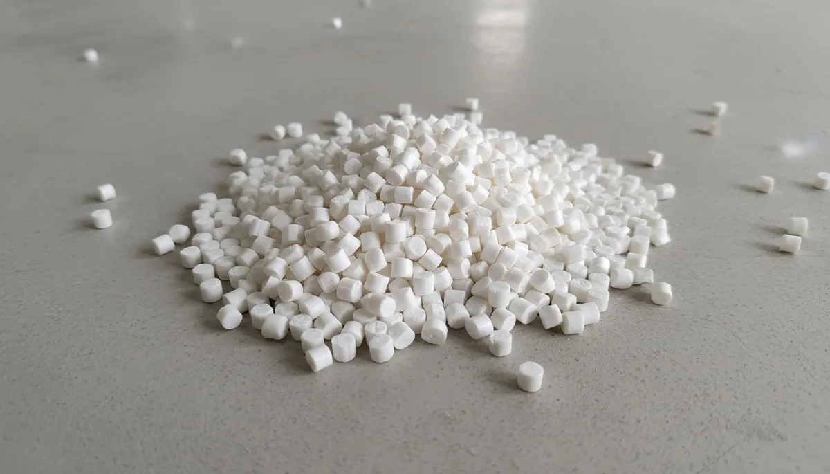
ランナー
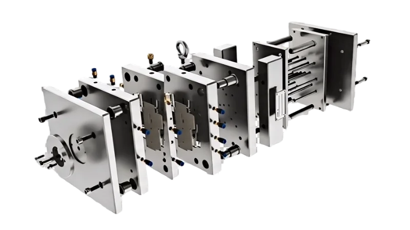
射出成形金型は通常、金型ベース、キャビティ・コアインサート、ランナーシステム(スプルー、ランナー、ゲート)、冷却チャネル、エジェクタピンとプレート、ガイドピンとブッシング、ベント溝、サポートピラー、およびスプリング、シール、リフターなどの各種補助部品を含みます — これらすべてが、プラスチック部品を繰り返し精度良く成形、冷却、離型するために設計されています。
This guide breaks down every major component group, explains what each part does, and shares practical insights from two decades of building and running injection molds in our Shanghai factory. If you are designing a new mold or troubleshooting an existing one, understanding these components is where good decisions start.
- An injection mold has 8+ component groups: cavity/core, runner, cooling, ejection, guiding, venting, support, and auxiliary systems
- The cavity and core define the part shape — their material and finish directly affect part quality
- Runner design (hot vs. cold) impacts material waste, cycle time, and production cost
- Cooling channels control cycle time and part warpage — conformal cooling can cut cycles by 20-40%
- Ejector pin type, count, and placement determine whether parts release cleanly or with damage

What Are the Core Components of an Injection Mold?
Every injection mold, regardless of complexity, shares a common set of core components that work together to form, cool, and eject plastic parts. Understanding these building blocks is essential for anyone involved in mold design, sourcing an injection molding supplier, or production.
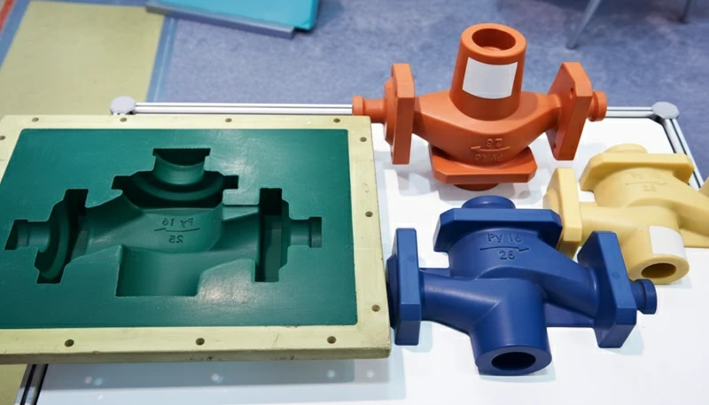
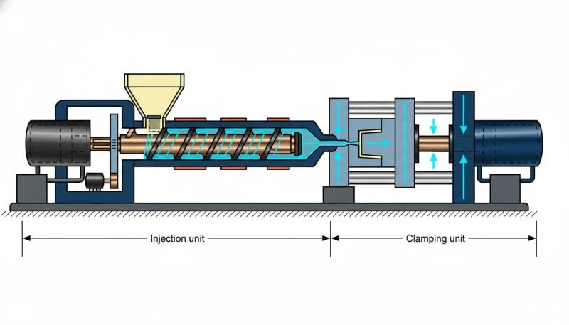
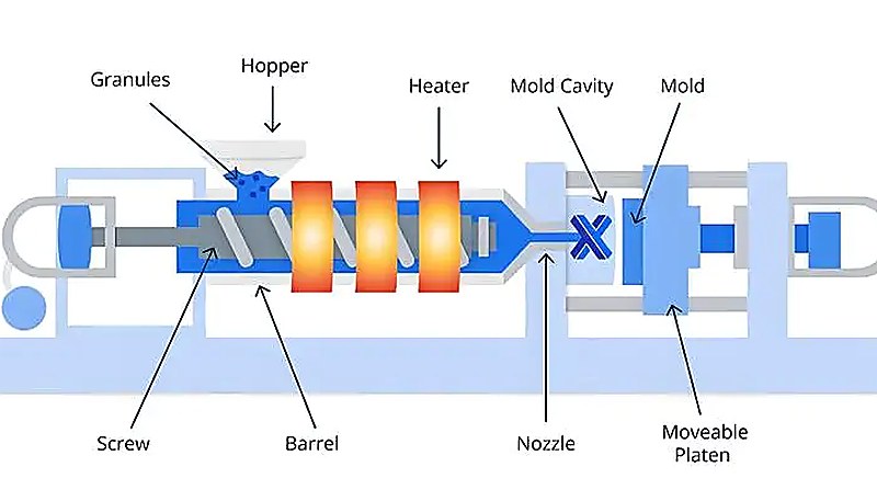
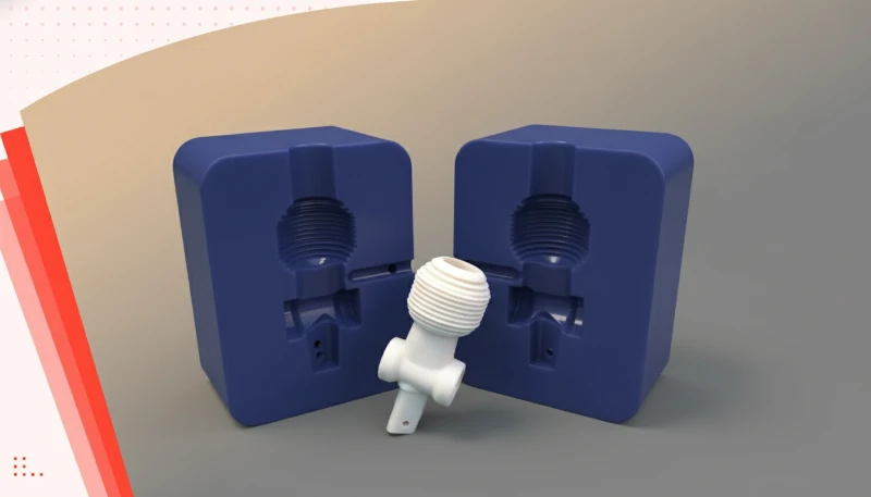
At the most fundamental level, an 射出成形金型 consists of two halves — the fixed (stationary) half and the moving half — mounted on the respective platens of the 射出成形 machine. When these two halves close, they create a sealed cavity that defines the shape of the final part. The fixed half typically contains the cavity (the concave side), while the moving half contains the core (the convex side).
金型ベース(金型フレームとも呼ばれる)は構造的な基礎です。すべてのインサート、プレート、サブシステムを精密に位置合わせして保持します。金型ベースは通常、P20やS50Cなどの中炭素鋼で作られ、数千トンのクランプ力に耐え、たわまないようにしなければなりません。これらの部品は直接的に 射出成形のステップ と合計 射出成形の生産時間なぜなら、充填、冷却、エジェクション、検査はすべて金型のレイアウトに依存するからです。
「射出成形金型は、精密に連携して動作しなければならない複数のサブシステムで構成されています。」真
The cavity, runner, cooling, ejection, guiding, venting, and support systems must all function together within tight tolerances — typically ±0.005 mm — for the mold to produce acceptable parts consistently.
「部品の複雑さに関わらず、すべての射出成形金型は同じ構成部品セットを使用します。」偽
Component selection varies widely: a simple single-cavity mold may use basic guide pins and straight-pull ejection, while a complex multi-cavity mold requires lifters, slides, hot runners, and sequential valve gates.
- Cavity and core inserts — the form-giving surfaces that define part geometry
- Runner system — channels that deliver molten plastic from the machine nozzle to the cavity
- 冷却システム — water or oil channels that extract heat from the molded part
- Ejection system — pins, sleeves, and plates that push the part out after cooling
- Guiding system — leader pins and bushings that ensure mold halves align perfectly
- Venting system — shallow grooves that allow trapped air and gases to escape
- Support system — pillars, spacer blocks, and return pins that maintain structural rigidity
In practice, a production-class mold for a medium-complexity part might contain 50 to 200 individual components. A multi-cavity mold for something like a medical syringe barrel could have over 500 precision-machined parts. Each component must be manufactured to tight tolerances — often within ±0.005 mm — because any misalignment or dimensional drift shows up directly on the finished part.
上海の当社工場では、90トンから1850トンまでの47台の射出成形機を、自社の金型製造設備のサポートのもとで稼働させています。金型製造と生産が一箇所で行われることで、金型部品の迅速な試作・改良が可能です — もし ejector pin1 再配置が必要な場合や冷却チャネルの拡大が必要な場合、変更は部品が成形されている同じフロアで行われます。
What Role Do the Cavity and Core Play in Mold Design?
The cavity and core are the heart of any injection mold — they are the surfaces that directly shape the plastic part. Get these right, and everything else becomes easier. Get them wrong, and no amount of process tuning will save the part.
について プラスチック部品が冷却して固化した後、型から取り出す必要があります — これは射出システムの仕事です。射出ピン⁴は最も一般的な射出要素ですが、システムには射出プレート、リターンピン、スプリング、ストリッパプレートも含まれ、場合によってはエアブラストバルブやロボットによる取り出しも使用されます。 is the concave (recessed) side of the mold that forms the external surfaces of the part. The core is the convex (protruding) side that forms the internal surfaces. When the mold closes, the gap between cavity and core defines the wall thickness and geometry of the molded part. This gap is the 金型キャビティ2 in the broader sense.
Material selection for cavity and core inserts is critical. For high-volume production (over 500,000 cycles), hardened tool steel such as H13, S136, or 8407 is standard. For shorter runs or prototypes, aluminum (such as 7075-T6) or P20 pre-hardened steel can reduce cost and lead time significantly. The surface finish of these inserts also transfers directly to the part — mirror-polished cavities produce glossy parts, while textured surfaces (applied via EDM or photo-etching) can hide flow marks and create grip patterns.
In practice, cavity and core design must account for material shrinkage. Every plastic material shrinks as it cools — typically 0.5% to 2.5% depending on the resin. The mold designer must scale the cavity dimensions by the expected shrinkage rate so that the final part meets specification after cooling. Getting this wrong means parts that are consistently oversized or undersized.
400種類以上のプラスチック材料にわたる経験を活かし、当社のエンジニアはMOLDFLOWシミュレーションを使用して、鋼材が切削される前に収縮、溶接線の位置、エアトラップの位置を予測します。当社チームはこの事前分析を、特にガラス充填ナイロンや繊維強化PPなどの高収縮率または異方性収縮率を持つ材料に対して、金型リスクチェックのツールとして扱います。
How Does the Runner System Deliver Molten Plastic?
The runner system is the network of channels that transports molten plastic from the injection machine nozzle into the mold cavity. Its design directly affects fill balance, material waste, cycle time, and part quality.
A runner system has four main elements: the sprue (the main channel from the nozzle), the runners (ガイドピンとも呼ばれる)および gates (the narrow entry points into the cavity), and the cold slug wells (pockets that catch cooled material at the front of the melt stream). In multi-cavity molds, runner balance — ensuring each cavity fills at the same rate and pressure — is a fundamental design requirement.
There are two broad categories of runner systems. コールドランナーシステム are simpler and cheaper. The plastic in the channels solidifies with each cycle and is ejected as waste (or reground and reused). Hot runner systems use heated manifolds and nozzles to keep the plastic molten inside the mold, eliminating runner waste entirely. Hot runners add upfront cost but pay off quickly in high-volume production.
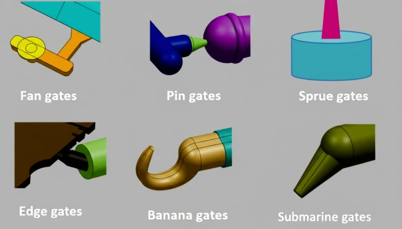
Gate design deserves special attention because the gate is where the melt enters the cavity and leaves a witness mark on the part. Common gate types include edge gates, submarine (tunnel) gates, pin-point gates, and valve gates. The choice depends on part geometry, aesthetic requirements, and whether gate vestige is acceptable on the visible surface.
In multi-cavity molds, achieving runner balance is essential for consistent part weight and dimensions across all cavities. Naturally balanced runners use equal-length paths from the sprue to each cavity, while artificially balanced runners adjust cross-section dimensions to equalize pressure drop. For high-precision parts with tight tolerances, even a 2-3% variation in fill time between cavities can produce measurable dimensional differences — which is why many production molds use valve-gated hot runner systems for positive shutoff and precise timing control.

「ホットランナーシステムは、プラスチックを金型内で溶融状態に保つことで、ランナーの廃棄物を排除します。」真
Heated manifolds and nozzles maintain the polymer above its melting point throughout the feed system, so no solidified runner is produced — saving material and reducing post-processing.
「ランナー設計は部品品質には影響せず、材料コストのみに影響します。」偽
Runner layout and gate placement critically affect fill pattern, weld-line position, air traps, packing pressure, and dimensional consistency — all of which directly influence part quality.
Why Is the Cooling System Critical for Part Quality?
Cooling accounts for 60-70% of the total injection molding cycle time. A well-designed cooling system produces consistent parts faster; a poor one leads to warpage, sink marks, longer cycles, and higher per-part cost.
The cooling system consists of a network of channels drilled through the mold plates, typically carrying temperature-controlled water (or oil for high-temperature applications). These channels are positioned as close to the cavity surfaces as possible to extract heat efficiently. The layout must balance cooling uniformity against structural integrity — you cannot drill channels so close to the cavity that the mold cracks under injection pressure.
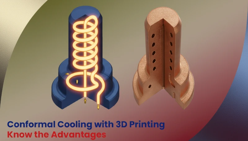
Traditional cooling uses straight, drilled channels, which work well for simple geometries. For complex parts with deep ribs or curved surfaces, conformal cooling3 channels — manufactured using metal 3D printing (DMLS/SLM) — follow the contour of the cavity surface. Studies have shown conformal cooling can reduce cycle time by 20-40% while improving dimensional consistency.
Cooling channel design also affects part aesthetics. Uneven cooling causes differential shrinkage, which shows up as warpage, sink marks on thick sections, or internal stress that leads to cracking later. Mold temperature must be matched to the material — running a mold too cold for a semi-crystalline material like nylon can cause premature freezing and incomplete fill.
The thermal conductivity of the mold steel itself also plays a role in cooling performance. Standard P20 steel has a thermal conductivity of about 30-35 W/(m·K), while beryllium copper inserts — sometimes used in hard-to-cool areas — offer 200+ W/(m·K), dramatically improving heat extraction. For molds running engineering resins that require higher mold temperatures (such as PEEK or LCP), oil-heated thermal regulators maintain mold temperature at 150-200°C rather than using water cooling.
In multi-cavity molds, cooling balance between cavities is just as important as the absolute cooling rate. If one cavity cools faster than its neighbors, the resulting dimensional variation between parts from the same shot can be significant enough to reject some cavities outright. Flow regulators or restrictors in the cooling circuit help equalize water distribution across all cavities, ensuring consistent part quality from every cavity in the mold.

「冷却時間は、射出成形サイクル全体の60-70%を占めます。」真
After the cavity is filled, the part must cool below its ejection temperature before the mold can open. This waiting period dominates cycle time, making cooling optimization the most effective lever for productivity.
「すべての冷却チャネルは、完璧に真っ直ぐなドリル穴でなければなりません。」偽
While traditional drilling produces straight channels, conformal cooling channels made via metal 3D printing can follow curved cavity surfaces, providing far more uniform cooling for complex geometries.
The relationship between cooling channel diameter and flow rate is also important. Larger diameter channels (10-14 mm) allow higher flow rates and better heat removal but remove more steel from the mold, potentially weakening the structure. Smaller channels (6-8 mm) maintain structural integrity but require higher pressure to achieve adequate flow. Most production molds use 8-10 mm channels as a practical compromise, with baffles or inserts to direct flow precisely where it is needed most.
Baffle design inside cooling channels also matters. Straight-through channels are the simplest, but baffled channels — where a blade redirects flow to make a U-turn inside the channel — provide better heat transfer by forcing water against the cavity surface. For cores and slender features, spiral cooling channels or bubbler tubes deliver water deep into the feature and back out again, preventing hot spots that cause differential shrinkage and warpage.
How Does the Ejection System Remove Finished Parts?
このセクションは、完成部品を取り出すエジェクションシステムと、それがコスト、品質、タイミング、調達リスクに与える影響について説明します。プラスチック部品が十分に冷却されると、金型からきれいに取り除かれなければなりません。エジェクションシステムがこの重要な工程を担当し、その設計によって、部品がきれいに、一貫して、外観損傷なく取り出されるかどうかが決まります。
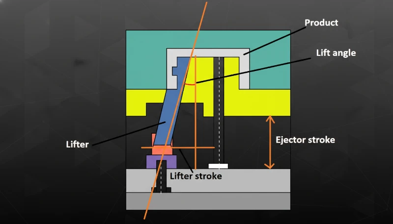
The core ejection components include ejector pins (straight round pins that push on the part), ejector sleeves (hollow pins that push around a core pin), stripper plates (full-face plates that strip the entire part off the core), and lifters (angled mechanisms that form and release undercuts). These are driven by an ejector plate 射出成形機の油圧または機械式エジェクションシステムによって作動し、一つのユニットとして動きます。
Ejector pin placement is a careful balance. Too few pins, and the part distorts or cracks during ejection. Too many pins, and you leave excessive witness marks on the part surface. The pins must push on areas of the part that are structurally rigid — ribs, bosses, or thick wall sections — rather than on thin walls that would deform.
For parts with undercuts (features that cannot be released in a straight pull), the mold needs side-action mechanisms: lifters for internal undercuts and slides for external undercuts. These add significant complexity and cost to the mold but are essential for features like snap fits, thread profiles, or lateral holes.
What Are the Guiding and Positioning Components?
Precision alignment between the two mold halves is non-negotiable. Even a few thousandths of a millimeter of misalignment creates flash (thin unwanted material at the parting line), mismatched wall thickness, or dimensional failure on the molded part.
The primary guiding components are leader pins (also called guide pins) and リフターおよびインサート用スループロファイル. Leader pins are mounted on one mold half (typically the moving side) and enter corresponding guide bushings on the opposite half as the mold closes. They engage before the cavity surfaces touch, ensuring the two halves are aligned before they bear the full clamping force.
For higher precision, molds also use tapered interlocks (also called locating rings or alignment locks). These are conical male-female pairs machined into the cavity and core inserts that provide final, tight alignment at the parting line. Straight leader pins handle coarse alignment; interlocks handle the last few microns.
In multi-plate molds (such as stripper-plate or three-plate molds), additional guide pin sets are needed to align each plate pair. Positioning pins (dowel pins) are also used throughout the mold to ensure inserts are locked in their correct positions and cannot rotate or shift under injection pressure.
What Auxiliary Components Enhance Mold Performance?
このセクションは、金型性能を向上させる補助部品と、それがコスト、品質、タイミング、調達リスクに与える影響について説明します。主要なサブシステムに加えて、さまざまな補助部品が金型の信頼性、耐久性、性能に貢献しています。これらは、故障するまでほとんど注目されない部品です。
Venting grooves are shallow channels (typically 0.01-0.03 mm deep) ground into the parting surface that allow trapped air and decomposition gases to escape ahead of the advancing melt front. Without adequate venting, the trapped air compresses and heats to the point of diesel ignition — a phenomenon called gas burn or dieseling that chars the plastic surface.
Springs (return springs, stripper springs) provide the return force for ejection plates and preload for slide mechanisms. Disc springs are common in high-force applications, while coil springs handle lighter duties. Spring fatigue is a frequent maintenance item — springs lose force over time, causing ejection issues or incomplete slide return.
Seals and O-rings prevent coolant leaks at channel intersections and plug interfaces. A coolant leak inside the mold is a serious problem — it causes rust, contaminates parts, and can short-circuit heater circuits in hot runner molds. O-ring material must be compatible with the coolant temperature and chemistry (EPDM for water, fluorocarbon for high-temperature oil).
「ベント溝が浅すぎると、空気が閉じ込められ、部品にガス焼けを引き起こします。」真
When vent depth is insufficient, compressed air reaches ignition temperature and causes diesel effect — charring the plastic surface with visible burn marks at the end of fill.
「冷却システムのOリングは、正しく取り付けられれば交換は一切不要です。」偽
O-rings degrade from thermal cycling, chemical exposure, and mechanical compression set. Most manufacturers recommend replacing coolant O-rings every 6-12 months as part of preventive maintenance.
Support pillars (also called support columns) sit between the B-plate and the support plate of the moving mold half. They prevent the B-plate from deflecting under injection pressure. Without adequate support, the plate bows, the parting line opens, and flash appears. The number and diameter of support pillars are calculated based on projected cavity area and peak injection pressure.
Other auxiliary components include heater bands and thermocouples (for hot runner temperature control), wear plates (replaceable surfaces that absorb sliding friction), chain pulleys そして limit switches (for sequential slide motion).
Maintaining 100+ mold sets per month means our tooling team handles auxiliary component wear every day. Vent cleaning, spring replacement, and O-ring swaps are part of our standard preventive maintenance protocol — not something that waits for a breakdown.
How Are Injection Molds Designed and Manufactured?
このセクションは、設計・製造された射出成形金型と、それがコスト、品質、タイミング、調達リスクに与える影響について説明します。生産レベルの射出成形金型の構築は、ソフトウェアシミュレーション、精密加工、熱処理、手仕上げを組み合わせた数か月にわたるエンジニアリングプロジェクトです。このプロセスを理解することで、金型の見積もり、納期、品質を評価するのに役立ちます。
The process starts with part design review and DFM (Design for Manufacturability). The mold designer analyzes the part geometry for features that complicate molding — undercuts, uneven wall thickness, deep ribs, tight tolerances — and recommends modifications before any steel is cut. This is where the most cost-effective decisions are made.
Next comes mold flow simulation using software like MOLDFLOW or Moldex3D. The simulation predicts fill pattern, weld-line locations, air traps, shrinkage, and cooling efficiency. The designer adjusts gate locations, runner dimensions, and cooling layout based on the simulation results. A good simulation run saves weeks of trial-and-error during mold commissioning.
After simulation, the 金型設計 is finalized in CAD (UG/NX, SOLIDWORKS, or similar). Every component — inserts, pins, bushings, springs, O-rings — is detailed with dimensions, tolerances, and material specifications. The completed design package includes assembly drawings, individual part drawings, and a bill of materials.
「金型流動シミュレーションは、鋼材を切削する前に、充填パターンや欠陥の発生位置を予測できます。」真
Software like MOLDFLOW and Moldex3D simulates the injection process digitally, allowing designers to optimize gate locations, runner dimensions, and cooling layout — saving weeks of physical trial-and-error.
「量産用金型は、量産開始前に1回の試作運転のみが必要です。」偽
Production molds typically go through 2-4 trial iterations to fine-tune gate size, vent depth, cooling balance, and ejection timing. Each trial produces samples that are measured and evaluated, with steel adjustments made between runs.
| Mold Manufacturing Step | Key Process | Typical Tolerance |
|---|---|---|
| CNC Milling | 3-5 axis machining of cavity/core blocks | ±0.005 mm |
| EDM (Sinker) | Burn-forming deep ribs and sharp corners | ±0.01 mm |
| Wire EDM | Through-profiles for lifters and inserts | ±0.005 mm |
| コンフォーマル冷却とは、従来のドリル加工されたチャネルと比較して、金型キャビティの輪郭に沿って配置されたチャネルを指し、より均一な冷却を提供し、サイクルタイムを短縮します。 | Flat parting surface preparation | ±0.002 mm |
| Polishing | Mirror, SPI A-1 to A-3 finish | Ra 0.012–0.025 μm |
Machining involves CNC milling (for cavity/core blocks and mold base), イーディーエム (Electrical Discharge Machining for fine details and sharp corners that cutters cannot reach), wire EDM (for through-profiles like angled lifters), surface grinding (for flat parting surfaces), and 研磨 (for mirror or specified surface finishes). Hardened inserts may go through multiple heat-treatment cycles during machining to relieve stress and achieve target hardness (typically 48-52 HRC for P20, 50-54 HRC for H13).
Finally, the mold is assembled, tested, and qualified through T1 (first trial) sampling. The T1 samples are measured against part drawings, and any necessary steel adjustments (adding vents, adjusting gate size, polishing sticky areas) are made. A production mold typically goes through 2-4 trial iterations before it is released for production.
Having built molds for 20+ years under ISO 9001, ISO 13485, ISO 14001, and ISO 45001 systems, our process is standardized from DFM review through T1 sampling. Every mold goes through documented quality gates — steel hardness verification, dimensional inspection of inserts, and at least two trial runs before we ship or start production.

Frequently Asked Questions About Injection Mold Components?
What is the difference between a cavity and a core in an injection mold?
The cavity is the concave (recessed) side of the mold that forms the external surfaces of the part, while the core is the convex (protruding) side that forms the internal surfaces. Together they define the complete geometry of the molded part, with the gap between them establishing wall thickness. In practice, the cavity is usually on the fixed (stationary) mold half and the core on the moving half, though this can vary depending on part geometry and ejection strategy. Understanding the distinction between these two components is essential when specifying mold requirements, reviewing DFM feedback, or troubleshooting flash and dimensional issues during production.
How many components does a typical injection mold have?
A standard single-cavity production mold typically contains 50 to 200 individual components, including cavity and core inserts, ejector pins, guide pins, cooling baffles, springs, and O-rings. Multi-cavity molds or those with complex side actions can contain 500 or more precision parts. Each component must be manufactured to tight tolerances, often within 0.005 mm, to ensure consistent part quality over thousands of production cycles. When evaluating mold quotes, understanding this component count helps you assess whether a supplier is proposing adequate tooling complexity or cutting corners on critical subsystems like cooling and ejection.
What material is used for injection mold components?
Cavity and core inserts are typically made from hardened tool steels such as H13, S136, P20, or 8407 for high-volume production molds. Mold bases use medium-carbon steel like S50C. Ejector pins are made from hardened SUJ2 bearing steel for wear resistance. For prototype or low-volume molds, aluminum alloys such as 7075-T6 can reduce cost and lead time by 30-50%. The choice of material depends on production volume, resin abrasiveness, required surface finish, and budget constraints. Your mold supplier should recommend specific grades based on your application rather than defaulting to a one-size-fits-all steel selection.
Why do injection molds need cooling channels?
Cooling channels circulate temperature-controlled water or oil through the mold to extract heat from the solidifying plastic part. Since cooling accounts for 60-70% of the total injection molding cycle time, efficient channel design is the single most effective lever for increasing production output and reducing per-part cost. Proper cooling also prevents common defects such as warpage, sink marks on thick sections, and internal residual stress by ensuring the part solidifies uniformly before ejection. Skipping cooling optimization during mold design is one of the most expensive mistakes you can make in tooling procurement.
What is the purpose of ejector pins in an injection mold?
エジェクターピンは、金型が開いた後に冷却固化した部品を金型キャビティから押し出すための焼入れ鋼棒です。これらは射出成形機の油圧または機械的エジェクションシステムによって作動するエジェクタープレートに取り付けられています。ピンの数、直径、配置は、部品を歪ませたり外観面に目立つ痕跡を残したりすることなく均一な取り出し力を加えるよう慎重に設計する必要があります。典型的な直径は部品のサイズに応じて2mmから12mmの範囲で、ピンは薄肉部ではなくリブやボスのような構造的に剛性のある部分を押すようにします。
Understanding injection mold components directly affects your ability to specify the right mold, evaluate supplier quotes, and troubleshoot production issues.
-
ejector pin: エジェクタピンは、硬化した鋼製の棒で、冷却後に成形部品をキャビティから押し出す役割を果たし、射出成形機のエジェクションシステムによって作動します。 ↩
-
mold cavity: mold cavity refers to a mold cavity is the hollow space within a mold that defines the external shape and surface finish of the molded part. ↩
-
conformal cooling: conformal cooling refers to channels follow the contours of the mold cavity, providing more uniform cooling and reducing cycle time compared to traditional drilled channels. ↩