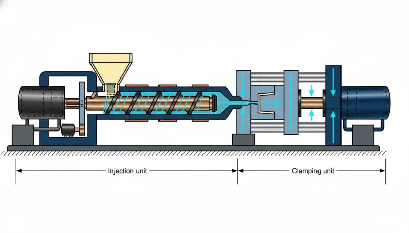
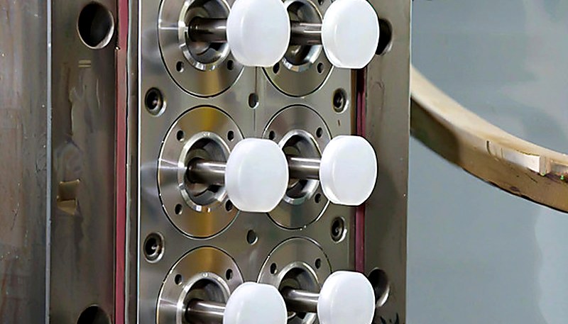
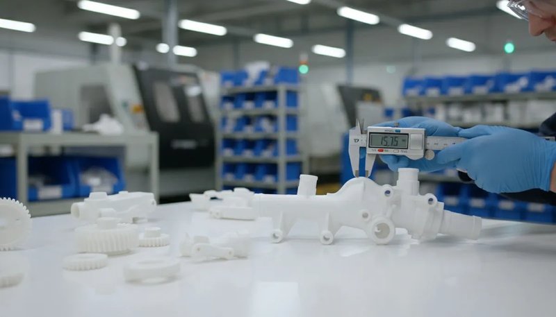
U hebt zojuist een nieuwe matrijs op een 200T-machine ingesteld. De eerste drie shots zien er goed uit, daarna ontstaan onvolledige vullingen. U stelt de nadruk bij, de temperatuur stijgt 5 graden en nu ontstaat braamvorming. Herkenbaar? De meeste spuitgietproblemen op de productievloer zijn terug te voeren op enkele machine-instellingen die operators over het hoofd zien of uit gewoonte in plaats van logisch instellen.
Dit artikel behandelt 18 praktische tips die er echt toe doen — de tips die we dagelijks toepassen bij het werken met 47 machines, zoals beschreven in onze complete gids over spuitgieten. Geen theorie omwille van de theorie, maar concrete zaken die het verschil maken tussen een stabiel proces en voortdurend brandjes blussen.
- Een tegendruk van 5–15 bar geeft een consistente smelt; boven 20 bar neemt slijtage toe met afnemend rendement.
- Het schroefkussen van 3–9 mm moet constant blijven — zelfs een afwijking van 1 mm verandert het onderdeelgewicht.
- De smelttemperatuur moet bij de spuitmond worden gemeten en niet worden afgeleid uit de cilinderinstellingen.
- Een matrijstemperatuurvariatie van ±2 °C kan de afmetingen van onderdelen uit technische harsen met 0.1–0.3 mm verschuiven.
- Gelijkmatige koeling — niet snelheid — is de werkelijke bepalende factor voor maatvastheid.
Wat zijn de belangrijkste machine-instellingen voor spuitgietbedrijven?
In dit gedeelte worden de belangrijkste categorieën en opties voor machine-instellingen voor spuitgieters toegelicht. Als u leveranciers vergelijkt of een inkooptraject voorbereidt, behandelt onze gids voor het inkopen bij een spuitgietleverancier de voorbereiding van de offerteaanvraag, kwalificatie en controle van commerciële risico’s.
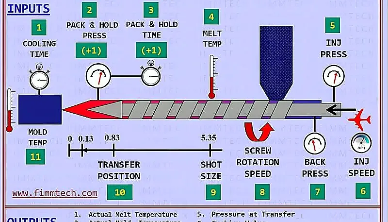
De vijf instellingen die 80% van de productieproblemen veroorzaken, zijn tegendruk1, schroeftoerental, smeltkussen2, smelttemperatuur en matrijstemperatuur. Als deze correct zijn ingesteld, verdwijnen de meeste defecten — zoals onvolledige vulling, inval en maatvariatie — zonder dat u secundaire parameters hoeft na te jagen.
Uit ervaring met ruim 400 materialen op 47 machines blijkt tegendruk de meest onderbenutte instelling. Veel operators laten de fabriekswaarde staan. Voor PP of PE is dat acceptabel; bij glasgevuld nylon of hogetemperatuurpolycarbonaat gaat daardoor kwaliteit verloren.
Beschouw deze vijf parameters als één systeem, niet als losse knoppen. Meer tegendruk voegt schuifwarmte toe, waardoor lagere cilindertemperaturen nodig kunnen zijn. Een hoger schroeftoerental doet hetzelfde. Elke wijziging werkt door. De beste operators wijzigen één parameter tegelijk en observeren minstens 10 opeenvolgende cycli voordat zij verder aanpassen.
Voordat we elke instelling uitvoerig bespreken, volgt hier het beknopte kader dat we op onze productievloer gebruiken: stel eerst de temperaturen in (cilinder en matrijs), vervolgens de drukken (tegendruk en nadruk), daarna de snelheden (schroef en injectie) en stel ten slotte de tijden nauwkeurig af (nadruk en koeling). Deze volgorde beperkt het aantal variabelen dat tegelijk verandert en maakt de probleemoplossing systematisch.
Hoe selecteert en onderhoudt u spuitmonden?
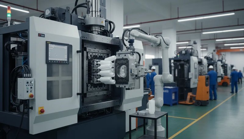
Open spuitmonden zijn geschikt voor 90% van de productieruns. Ze zijn goedkoper en eenvoudiger en hebben minder dode zones waarin materiaal kan degraderen. Gebruik gesloten spuitmonden (met afsluiter) alleen bij laagviskeuze harsen zoals PA6 of POM op een machine zonder schroefdecompressie — en zelfs dan moet de afsluitklep elke 2,000 cycli worden geïnspecteerd.
De radius van de spuitmondtip moet 0,5 mm kleiner zijn dan de radius van de aanspuitbus. Een verschil van 1 mm in diameter klinkt onbeduidend, maar veroorzaakt nadruppelen, draadvorming en koude proppen in het kanaal. We controleren de uitlijning van de spuitmond bij elke matrijswissel — dit kost 30 seconden met een hoogtemeter en voorkomt uren aan defecten.
Overweeg voor menggevoelige materialen (kleurwissels van masterbatch, vlamvertragende mengsels) een statische mixer tussen cilinder en nozzle. Deze voegt 50 mm aan het smeltpad toe, maar vermindert kleurstreepdefecten met ongeveer 60%. De afweging is een lichte toename van het drukverlies — circa 10–15 bar — die u compenseert door de injectiedruk te verhogen.
Nozzleonderhoud is een van die taken die wordt overgeslagen wanneer de productie druk is. Maar een nozzle met opgehoopte verkoolde resten verandert de effectieve uitstroomdiameter, en daarmee de afschuifsnelheid en smelttemperatuur bij het aanspuitpunt. Voor technische harsen plannen we elke 3,000 cycli demontage en reiniging van de nozzle, en voor standaardmaterialen elke 5,000 cycli.
Waarom bepaalt tegendruk de kwaliteit van de smelt?
Dit gedeelte legt uit waarom tegendruk bepalend is voor de smeltkwaliteit en welke gevolgen dit heeft voor kosten, kwaliteit, doorlooptijd en inkooprisico. Tegendruk is de meest onderschatte instelling van een spuitgietmachine: ze regelt rechtstreeks de homogeniteit van de smelt, de kleurconsistentie en de stabiliteit van het schotgewicht. Voor de meeste technische kunststoffen ligt het optimale bereik tussen 5–15 bar. Bij een te lage tegendruk (0–3 bar) ontstaan ongesmolten korrels, kleurwervelingen en een wisselend schotgewicht. Een te hoge tegendruk (25+ bar) leidt tot een langere cyclustijd3, overmatige schuifwarmte en versnelde slijtage van de schroef.
Het praktische bereik voor de meeste technische harsen is 5–15 bar. Begin bij 8 bar, voer een vrij schot uit en controleer op gelijkmatige extrusie. Als de smelt melkachtig oogt of zichtbare korrels bevat, verhoogt u de druk in stappen van 2 bar. Voor PC of PEEK kan 12–18 bar nodig zijn vanwege de hoge viscositeit.
Een veelgemaakte fout: operators verhogen de tegendruk om een versleten schroef te compenseren. Dat werkt tijdelijk, maar de echte oplossing is inspectie van schroef en cilinder. Als het restkussen afdrijft en de doseertijd blijft oplopen, is de schroefgang waarschijnlijk verder versleten dan 0.5 mm speling. Dan herstelt geen enkele tegendrukaanpassing de procesconsistentie.
Een ander subtiel punt: tegendruk werkt samen met schroefdecompressie (suck-back). Hoge tegendruk gevolgd door agressieve suck-back kan luchtbellen in de smelt trekken. De oplossing is eenvoudig: verlaag de tegendruk iets of beperk de suck-backafstand tot 2–3 mm. Bij machines met ontluchte cilinder die hygroscopische harsen verwerken, is deze combinatie bijzonder belangrijk.
"Een verhoging van de tegendruk van 3 bar naar 10 bar kan kleurwervelingsdefecten met meer dan 50% verminderen bij ABS-onderdelen."True
Een hogere tegendruk verbetert de dispersie van kleurstof in de smelt doordat materiaal door nauwere spelingen tussen schroefgangen en cilinderwand wordt gedrukt, wat een consistentere pigmentatie in het volledige shotvolume oplevert.
"Een hogere tegendruk levert altijd een betere onderdeelkwaliteit op."False
Overmatige tegendruk (meer dan 20 bar voor de meeste harsen) genereert te veel schuifwarmte, breekt de polymeerketens af, verlengt de cyclustijd door langer schroefherstel en versnelt slijtage van schroef en cilinder. Het optimum is materiaalspecifiek en ligt doorgaans tussen 5 en 15 bar.
Welke invloed heeft het schroeftoerental op het plastificeren en de consistentie van onderdelen?
De schroefsnelheid bepaalt rechtstreeks de uniformiteit van de smelttemperatuur en de kleurconsistentie — voor de meeste machines is 50–100 tpm het optimale bereik. Snellere rotatie genereert meer wrijvingswarmte, maar levert een minder uniforme smelt op; langzamere rotatie zorgt voor betere menging, maar het herstel is mogelijk niet voltooid voordat de matrijs opent. De sleutel is de schroefsnelheid zo af te stellen dat het herstel 1–2 seconden vóór het openen van de matrijs is voltooid.
De vuistregel: stel de schroefsnelheid zo in dat het doseren 1–2 seconden vóór het openen van de matrijs is voltooid. Als de schroef nog doseert wanneer de matrijs opent, verliest u koeltijd en legt u onnodige druk op de operator. Als het doseren ruim vóór het openen is voltooid, kunt u de schroef vertragen en de schuifwarmte verminderen.
Verschillende materialen vereisen verschillende schroeftoerentallen. PVC en PMMA zijn afschuifgevoelig — houd het schroeftoerental onder 60 rpm om degradatie te voorkomen. POM en PA66 verdragen 80–120 rpm. PEEK en LCP profiteren ondanks hun hoge smelttemperaturen juist van een gematigd schroeftoerental (40–80 rpm), omdat hun lage viscositeit minder afschuifverwarming vereist.
Ook het schroeftoerental beïnvloedt de kleurconsistentie. Bij zeer lage toerentallen (<30 rpm) kan de smelt onvoldoende homogeen zijn voor een gelijkmatige kleur. Bij zeer hoge toerentallen (>120 rpm op kleine machines) kan plaatselijke oververhitting kleurstrepen of verbranding veroorzaken. Een middenwaarde in combinatie met de juiste tegendruk geeft de beste smeltkwaliteit en kleurgelijkmatigheid.
Wat is het schroefkussen en waarom moet dit constant blijven?
Het schroefkussen² is de kleine hoeveelheid smelt die aan het einde van de injectie vóór de schroef achterblijft. Streef bij kleine machines naar 3 mm. Streef bij grote machines (1000T+) naar 6–9 mm. Het exacte getal is minder belangrijk dan de consistentie — als het kussen per shot 2 mm varieert, schommelt het onderdeelgewicht en ontstaat maatafwijking.
Moderne machines kunnen het restkussen binnen ±0.1 mm houden. Bij ±1 mm variatie controleert u: (1) lekkage van de terugslagklep, (2) onregelmatige toevoer en (3) een versleten cilinder in de doseerzone. In onze werkplaats controleren we eerst de kussenconsistentie als een klant maatafwijkingen meldt bij een onderdeel dat eerder goed liep.
Schroefterugtrekking (decompressie) houdt hiermee verband, maar is iets anders. Na injectie en vóór het openen van de matrijs trekt de schroef iets terug om de smelt te decomprimeren en nadruppelen van de spuitmond te voorkomen. Typische terugtrekking is 3–5 mm. Verminder die bij ontluchte cilinders met hygroscopische materialen tot 2 mm — lucht in de smelt trekken creëert bellen die als zilverstrepen op het onderdeeloppervlak verschijnen.
Denk bij het instellen van het kussen aan het volgende: de kussenwaarde die u in de machinebesturing programmeert, veronderstelt dat het nulpunt van de schroef correct is. Stel de schroefpositie na demontage en reiniging van de schroef altijd opnieuw op nul. We hebben gevallen gezien waarin een kussen van 3 mm in werkelijkheid 0 mm was doordat het nulpunt tijdens de montage verschoof. Daardoor werd geen nahoudruk overgedragen en ontstonden bij de eerste instelling 100% onvolledig gevulde onderdelen.
Hoe berekent en verifieert u de plastificeercapaciteit?
Plastificeercapaciteit³ is de snelheid waarmee uw machine materiaal gelijkmatig kan smelten, uitgedrukt in kg/h PS-equivalent. Deze specificatie staat in de handleiding van elke machine. Het probleem is dat de meeste gebruikers nooit controleren of hun werkelijke cyclustijd de smeltcapaciteit van de machine overschrijdt.
Gebruik deze formule: tmin = (totaal schotgewicht in g × 3600) ÷ (plastificeersnelheid in kg/h × 1000). Als de werkelijke cyclustijd korter is dan tmin, kan de machine het materiaal niet snel genoeg smelten. Dit leidt tot een wisselende viscositeit, onvolledige vulling in latere caviteiten en variatie in oppervlakteglans binnen het schot.
Dit is vooral cruciaal bij matrijzen met meerdere holten en een hoog shotgewicht. Als uit uw berekening blijkt dat u 85% of meer van de plastificeercapaciteit gebruikt, moet u de koeltijd verlengen, het aantal holten verminderen of overstappen op een grotere machine. Draaien op de grens van de plastificeercapaciteit leidt onvermijdelijk tot uitval.
Nog een aandachtspunt: de plastificeercapaciteit neemt gedurende de levensduur van de machine af. Een versleten schroef met grotere speling tussen de schroefgangen kan niet dezelfde afschuiving en compressie opwekken als een nieuwe. Als onderdelen uit een oudere machine consequent meer kleurvariatie of ongesmolten materiaal vertonen dan dezelfde matrijs op een nieuwere machine, laat dan de schroef en cilinder opmeten. Slijtage van 0,3–0,5 mm op de schroefgangdiameter kan de effectieve plastificeercapaciteit met 15–25% verminderen.
Waarom is beheersing van de smelttemperatuur cruciaal?
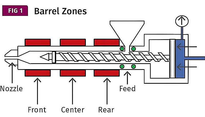
De ingestelde cilindertemperaturen zijn niet de smelttemperatuur, maar setpoints van verwarmingsbanden. De werkelijke smelttemperatuur wordt beïnvloed door schroefsnelheid, tegendruk, shotvolume en verblijftijd⁵. Alleen meting bij de spuitmond met een pyrometer of via de air-shotmethode is betrouwbaar.
Draag bij het vrij extruderen hittebestendige handschoenen en een gelaatsscherm. Extrudeer een kleine hoeveelheid smelt in een metalen bak en steek er een voorverwarmde thermokoppelsonde in. De gemeten waarde moet binnen ±5 °C van het door de materiaalleverancier aanbevolen bereik liggen. Ligt deze 10–15 °C hoger, dan voegt de schuifverwarming door schroefsnelheid en tegendruk te veel energie toe — verlaag één van beide of beide.
Ook het temperatuurprofiel is belangrijk. Stel de achterste zone (toevoer) het koelst in om voortijdig smelten en brugvorming te voorkomen. Verhoog de temperatuur stapsgewijs richting de spuitmond. De spuitmondpunt kan 5–10 °C lager worden ingesteld dan de voorste zone om nadruppelen te voorkomen. Als u geen ervaring hebt met een bepaalde hars, begin dan altijd bij de laagste aanbevolen temperatuur en verhoog deze in stappen van 5 °C.
Bij ZetarMold draaien in onze fabriek in Shanghai 47 spuitgietmachines van 90T tot 1850T. Met 20+ jaar vormervaring sinds 2005 en 8 senior matrijsengineers standaardiseren wij de verificatie van de smelttemperatuur bij elke productie-instelling: vóór goedkeuring van het eerste artikel moet de operator bevestigen dat de werkelijke smelttemperatuur aan de spuitmond binnen ±5 °C van het procesblad ligt.
"Het meten van de smelttemperatuur met een air shot is nauwkeuriger dan vertrouwen op de instelwaarden van de cilinderverwarming."True
Cilinderthermokoppels zijn in de stalen wand ingebed en meten de staaltemperatuur, niet de polymeertemperatuur. Afschuifverwarming door schroefrotatie en tegendruk kan de werkelijke smelttemperatuur 10–30 °C boven het instelpunt van de cilinder verhogen, waardoor directe meting essentieel is voor procesbeheersing.
"Voor het gemak moeten alle verwarmingszones op dezelfde temperatuur worden ingesteld."False
Een juist temperatuurprofiel begint koeler bij de invoerzone om brugvorming te voorkomen, loopt in de overgangszone op voor geleidelijk smelten en kan bij de spuitmondpunt iets lager zijn om nadruppelen te voorkomen. Gelijke instellingen voor alle zones veroorzaken invoerproblemen en inconsistent smelten.
Hoe zit het met verblijftijd en materiaaldegradatie?
De verblijftijd — hoe lang kunststof in de verwarmde cilinder blijft — is de belangrijkste oorzaak van thermische degradatie bij spuitgieten. Elk polymeer heeft bij een bepaalde temperatuur een maximale veilige verblijftijd; overschrijding leidt tot verlies van molecuulgewicht, verkleuring, gasvorming en verzwakte onderdelen die de visuele inspectie kunnen doorstaan maar tijdens gebruik bezwijken.
Bereken de verblijftijd als volgt: tresidence = (cilindervolume in g × cyclustijd in s) ÷ (schotgewicht in g × 300). Dit levert een benadering op. De werkelijke tijd is altijd langer, omdat materiaal in dode zones achterblijft. Voer voor precisiewerk een kleurspoeltest uit: voeg gekleurde korrels toe en meet hoelang het duurt voordat de kleur in het schot verschijnt.
Het grootste risico: machines met een grote cilinder die kleine shotgewichten verwerken. Als uw shot minder dan 30% van de cilindercapaciteit gebruikt, kan de verblijftijd gemakkelijk boven de veilige grens uitkomen. Gebruik een kleinere machine of spoel de cilinder tijdens lange productieruns elke 15–20 minuten. Bij sterk degraderende materialen zoals POM of PVC moet een shotbenutting onder 20% volledig worden vermeden.
Let op vroege tekenen van degradatie: zilverstrepen, lichtbruine of gelige verkleuring, een zwakke scherpe geur bij de nozzle of een geleidelijke daling van het onderdeelgewicht zonder proceswijzigingen. Dit wijst erop dat het materiaal in de cilinder wordt afgebroken. Stop en purgeer onmiddellijk zodra u deze tekenen ziet — doorwerken met degraderend materiaal verontreinigt de cilinder en verergert het probleem bij volgende schoten.
Hoe moet de matrijstemperatuur worden geregeld?
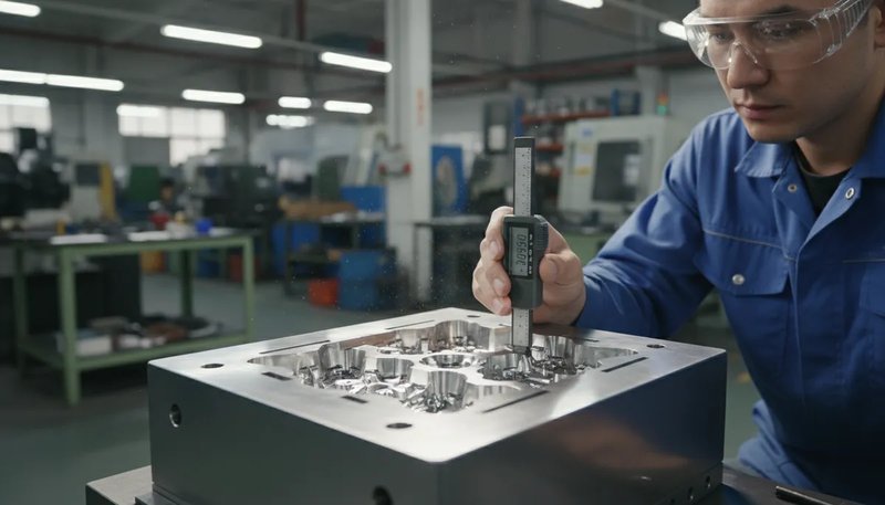
Dit gedeelte gaat over de beheersing van de matrijstemperatuur en de invloed daarvan op kosten, kwaliteit, planning en inkooprisico. De matrijstemperatuur moet met een contactthermometer op het oppervlak van de matrijsholte worden gecontroleerd — vertrouw nooit alleen op het display van de temperierunit, dat 5–15 °C kan afwijken. Houd bij onderdelen met nauwe toleranties de variatie binnen ±2 °C door voor elk circuit een afzonderlijke temperierunit te gebruiken. De matrijstemperatuur regelt rechtstreeks de oppervlakteafwerking, kristalliniteit, krimp en vervorming.
Controleer de matrijstemperatuur altijd met een contactthermometer op het holteoppervlak, niet via het thermolator-display. Het display toont de koelmiddeltemperatuur bij de unit, die 5–15 °C kan afwijken van het werkelijke holteoppervlak door circuitlengte, debiet en kalkaanslag in de kanalen.
Houd bij onderdelen met nauwe toleranties de variatie in matrijstemperatuur binnen ±2 °C. Op onze productievloer betekent dit dat we voor kritieke matrijzen per matrijscircuit een afzonderlijke temperatuurregelaar gebruiken — niet meerdere circuits in serie op één unit. Dat vergt meer apparatuur, maar nabewerking en uitval door maatafwijkingen kosten meer, vooral bij meerholtematrijzen waar één circuit dat 5 °C warmer draait de helft van de holten buiten specificatie brengt.
Een veelgemaakte fout is de matrijstemperatuur instellen op basis van wat bij een vergelijkbaar materiaal in een andere matrijs werkte. Matrijsgrootte, circuitindeling en wanddikte beïnvloeden allemaal de werkelijke oppervlaktetemperatuur van de caviteit. Een instelling van 60 °C kan bij een kleine, eenvoudige matrijs 55 °C aan het oppervlak opleveren, terwijl dezelfde instelling bij een grote matrijs met lange koelcircuits slechts 42 °C bereikt. Meet elke matrijs, elke keer.
Waarom is gelijkmatige koeling belangrijker dan snelle koeling?
Gelijkmatige koeling is belangrijker dan snelle koeling, gezien de afwegingen tussen kosten, kwaliteit, volume en toepassing. De meeste operators proberen de matrijs zo snel mogelijk te koelen om de cyclustijd te verkorten, zoals besproken in onze complete gids over spuitgietmatrijsontwerp. Snelheid is belangrijk, maar gelijkmatigheid is belangrijker. Ongelijkmatige koeling veroorzaakt verschillen in krimp, met kromtrekken, inwendige spanning en afmetingen buiten tolerantie als gevolg — zelfs als de cyclustijd er op papier uitstekend uitziet.
De contra-intuïtieve techniek: laat koeler water door de kern (binnenzijde van het onderdeel) en warmer water door de matrijsholte (buitenzijde) stromen. Dit maakt de afkoelsnelheid van dikke en dunne secties gelijk. Bij vlakke precisieonderdelen — denk aan optische lenzen, afdichtingsvlakken of passende behuizingen — kan dit alleen al het kromtrekken met 40–60% verminderen.
Controleer het debiet van het koelcircuit bij elke matrijswissel. Een circuit dat bij de vorige run 12 L/min leverde, kan door kalkaanslag zijn gedaald tot 4 L/min. Een laag debiet maakt turbulente stroming laminair, verlaagt de warmteoverdracht met 30–50% en maakt zorgvuldig ingestelde temperaturen betekenisloos. Als het debiet onder 60% van het oorspronkelijke niveau daalt, reinig of vervang dan het circuit voordat de productie start.
Bij matrijzen met meerdere holtes is een evenwichtige koeling van alle holtes cruciaal. De holte die het dichtst bij de waterinlaat ligt, koelt altijd het snelst. Gebruik debietrestrictoren of een afzonderlijk circuit per holte om de koeling gelijk te maken. Bij matrijzen met acht holtes hebben wij in één serieel circuit een temperatuurverschil van 8 °C gemeten tussen de eerste en laatste holte — voldoende om meetbare maatvariatie tussen onderdelen te veroorzaken.
Wat zijn de meest over het hoofd geziene tips voor spuitgieters?
De meest onderschatte tips voor spuitgieters zijn de belangrijkste categorieën of opties die in dit hoofdstuk worden toegelicht. Naast de vijf kerninstellingen zorgen diverse secundaire factoren regelmatig voor verrassingen:
Tip 14: controleer de terugslagklep. De ringvormige terugslagklep aan de schroefpunt slijt geleidelijk. Zodra de speling groter is dan 0.1 mm, wordt de nadrukdruk instabiel. Inspecteer de klep na elke 500,000 schoten of zodra de variatie in het smeltkussen groter is dan ±0.5 mm. Een nieuwe terugslagklep kost enkele honderden dollars; produceren met een versleten exemplaar kost duizenden dollars aan uitval.
Tip 15: ontlucht de matrijs goed. Ingesloten lucht veroorzaakt verbranding, het dieseleffect en onvolledige vulling in doodlopende zones. Ontluchtingskanalen aan de deellijn moeten 0.01–0.02 mm diep en schoon zijn, en mogen niet zijn dichtgepolijst na eerdere braamvorming. Plaats ontluchtingspennen aan het einde van vloeitrajecten en in blinde uitsparingen waar lucht van nature wordt ingesloten.
Tip 16: droog het materiaal correct. Hygroscopische kunststoffen (PC, Nylon, PET, TPU) nemen vocht op, wat zilverstrepen, moleculaire degradatie en verzwakte laslijnen veroorzaakt. PC moet 3–4 uur bij 120 °C worden gedroogd, met een dauwpunt lager dan –20 °C. Materiaal dat er ‘droog uitziet’ is niet per definitie droog: controleer het vóór elke productierun met een vochtmeter.
Tip 17: leg alles vast. Noteer elke parameterwijziging, elke temperatuurmeting en elke caviteitsmaat van de eerste 10 schoten. Als op dag 3 van de productie problemen ontstaan, hebt u deze uitgangswaarden nodig. Wij eisen dat alle operators vóór de goedkeuring van het eerste product een instelrapport invullen. De 10 minuten voor documentatie besparen later uren aan discussies over de schuldvraag.
Tip 18: vertrouw op de gegevens, niet op uw intuïtie. Als het procesblad een smelttemperatuur van 240 °C en een matrijstemperatuur van 60 °C voorschrijft en de onderdelen er goed uitzien, ga dan bij de volgende run niet ‘op gevoel optimaliseren’. Gedocumenteerde, reproduceerbare procesvensters zijn altijd betrouwbaarder dan het oordeel van een operator. Zo bereikt u een constante kwaliteit met meer dan 120 productiemedewerkers in meerdere ploegen.
Wat zijn de meestgestelde vragen over tips voor spuitgieten?
Wat is de ideale tegendruk voor spuitgieten?
De ideale tegendruk voor de meeste technische harsen is 5–15 bar. Begin bij 8 bar voor materialen voor algemeen gebruik zoals ABS en PP. Verhoog tot 12–18 bar voor hoogviskeuze harsen zoals polycarbonaat of PEEK. Meer dan 20 bar levert afnemende kwaliteitswinst op, terwijl de schroefslijtage wordt versneld en de cyclustijd wordt verlengd. Verifieer het resultaat altijd met een air-shotcontrole. Op onze 47 machines die meer dan 400 materialen verwerken, blijkt dat een tegendruk van 8–12 bar voor ongeveer 80% van de productietaken probleemloos volstaat.
Hoeveel schroefkussens moet ik aanhouden?
Houd een 3 mm kussen aan op machines onder 300T en 6–9 mm op machines boven 1000T. De belangrijkste maatstaf is consistentie — het kussen mag niet meer dan ±0,5 mm variëren van schot tot schot. Grotere variatie duidt meestal op een versleten terugslagklep, inconsistente materiaalaanvoer of slijtage van de cilinder in de doseerzone. Controleer en verhelp de oorzaak in plaats van te compenseren met andere parameters. In onze fabriek registreren operators kussenwaarden elke 50 schoten; elke trend die meer dan ±1 mm overschrijdt, leidt tot een klepinspectie voordat de run wordt voortgezet.
Hoe controleer ik de werkelijke smelttemperatuur?
Gebruik de ‘air-shot’-methode met een voorverwarmde pyrometer-sonde. Extrudeer een kleine smeltmonster in een metalen container terwijl je hittebestendige handschoenen en een gelaatsscherm draagt, en steek de sonde er onmiddellijk in. De meting moet binnen ±5 °C van het bereik op het materiaalgegevensblad liggen. De instelwaarden van de cilinderverwarmers zijn geen betrouwbare indicatoren voor de smelttemperatuur, omdat afschuifverhitting door de schroefrotatie de werkelijke temperatuur 10–30 °C boven de instelwaarden kan verhogen. Voor kritieke klussen raden we aan om aan het begin van elke ploeg en na elke snelheids- of tegendrukverandering een ‘air-shot’-meting te doen.
Waarom vervormen mijn spuitgietonderdelen?
Vervorming treedt op wanneer de variatie in koelsnelheid over het onderdeel meer dan 15 °C bedraagt, meestal door een ongelijke wanddikte die een verhouding van 3:1 overschrijdt of een ontoereikend koelcircuitontwerp. Verbeter eerst de koeluniformiteit door koeler water aan de kernzijde en warmer water aan de holtezijde te laten stromen. Deze differentiële koeltechniek vermindert vervorming met 40–60% op vlakke precisieonderdelen zonder de cyclusduur significant te veranderen. Controleer ook of de plaatsing van de ingietopening een gebalanceerde vulling ondersteunt — asymmetrische vulling veroorzaakt interne spanningen die vervorming versterken, zelfs bij uniforme koeling.
Hoe vaak moeten spuitgietspuitmonden worden geïnspecteerd?
Inspecteer open spuitmonden bij elke matrijsverwisseling op uitlijning en slijtage van de tipradius — de tipradius moet 0,5 mm kleiner zijn dan de radius van de tuitbus. Inspecteer afsluitende (gesloten) spuitmonden elke 2.000 cycli op de integriteit van de klepzitting. Plan het verwijderen en reinigen van spuitmonden elke 3.000 cycli voor technische kunststoffen en elke 5.000 cycli voor standaardmaterialen om ophoping van verkoolde resten te voorkomen. Tijdens piekproductiemaanden verwisselt ons team wekelijks de spuitmonden op machines die glasgevuld nylon verwerken, omdat slijtage door abrasie aanzienlijk versnelt bij gevulde composieten.
Wat gebeurt er als de verblijftijd in de cilinder te lang is?
Overmatige verblijftijd veroorzaakt thermische degradatie: molecuulgewicht daalt, verkleuring treedt op (gele of bruine tint), gasvorming neemt toe en mechanische eigenschappen verslechteren. Het risico is het grootst wanneer het shotgewicht minder dan 30% van de cilindercapaciteit gebruikt. Spoel de cilinder elke 15–20 minuten tijdens dergelijke runs, of ga over naar een kleinere machine. Let op vroege tekenen zoals zilverachtige strepen of een bijtende geur. Bereken de verblijftijd door het cilindervolume te delen door het shotvolume en te vermenigvuldigen met de cyclusduur — als dit 5 minuten overschrijdt voor de meeste technische kunststoffen, zit je in de degradatiezone.
Hoe bereken ik of mijn machine voldoende plastificeercapaciteit heeft?
Deel het totale shotgewicht in gram door 1000, vermenigvuldig met 3600 en deel vervolgens door de nominale plastificeercapaciteit van de machine in kg/h. Het resultaat is uw minimale cyclustijd in seconden. Als uw werkelijke cyclustijd korter is dan dit berekende minimum, kan de machine het materiaal niet snel genoeg smelten om een consistente kwaliteit te bereiken; u zult variaties in viscositeit en oppervlaktedefecten zien. Hanteer altijd een marge van 10–15% boven het berekende minimum om rekening te houden met verschillen tussen materiaalpartijen en veranderingen in de omgevingstemperatuur die de werkelijke doorvoer beïnvloeden.
Moeten alle koelcircuits voor mallen dezelfde watertemperatuur gebruiken?
Nee. Voor onderdelen met aanzienlijke variatie in wanddikte, gebruik differentiële koeling: koeler water (10–15 °C lager) aan de kernzijde en warmer water aan de holtezijde. Dit egaliseert de koelsnelheden tussen dikke en dunne secties en vermindert vervorming met 40–60%. Voor matrijzen met meerdere holtes, gebruik individuele circuits per holte of debietbegrenzers om de koeling over alle holtes te balanceren. In onze fabriek in Shanghai controleren we de debieten van de koelcircuits bij elke matrijsverwisseling met een debietmeter — een circuit dat minder dan 80% van zijn ontwerpdebiet levert, wordt ontkalkt of vervangen voordat de productie begint.
tegendruk: Tegendruk is de weerstand die tijdens de terugloopslag op de schroef wordt uitgeoefend. Ze wordt gemeten in bar of MPa en regelt de homogeniteit van de smelt en de mengkwaliteit in de spuitcilinder. ↩
smeltkussen: Het smeltkussen, ook schroefkussen of restkussen genoemd, is het kleine volume gesmolten kunststof dat na het inspuiten vóór de schroefpunt achterblijft, doorgaans 3–9 mm. Het zorgt voor een consistente drukoverdracht naar de caviteit. ↩
cyclustijd: De cyclustijd is de totale verstreken tijd vanaf het begin van één spuitgietschot tot het begin van het volgende. Ze wordt gemeten in seconden en omvat de inspuit-, nadruk-, koel- en uitwerpfase. ↩