 Ir al contenido

Al configurar el cushion, recuerda: el valor de cushion que programas en el controlador de la máquina supone que el punto cero del tornillo es correcto. Después de un pull del tornillo y limpieza, siempre vuelve a cero la posición del tornillo. Hemos visto casos donde un cushion de 3 mm era en realidad 0 mm porque el punto cero se desplazó durante el reensamblaje — resultando en ninguna transferencia de presión de retención y 100% short shots en el primer intento de setup.
This article walks through 18 practical tips that actually matter — the ones we use every day running complete injection molding guide en 47 máquinas. No teoría por sí misma. Solo cosas que marcan la diferencia entre una ejecución estable y un combate.
- Back pressure of 5–15 bar gives consistent melt; above 20 bar adds wear with diminishing returns.
- Screw cushion of 3–9 mm must stay constant — even a 1 mm drift changes your part weight.
- Melt temperature should be measured at the nozzle, not assumed from cylinder settings.
- Mold temperature variation of ±2 °C can shift part dimensions by 0.1–0.3 mm on engineering resins.
- Cooling uniformity — not speed — is the real driver of dimensional stability.
What Are the Most Critical Machine Settings for Injection Moulders?
The most critical machine settings for injection moulders are the main categories or options explained in this section. If you are comparing vendors or planning procurement, our proveedor de moldeo por inyección sourcing guide covers RFQ prep, qualification, and commercial risk checks.
The five settings that cause 80% of production issues are contrapresión1, screw speed, cushion2, melt temperature, and mold temperature. If you get these right, most defects — short shots, sink marks, dimensional drift — resolve themselves without chasing secondary parameters.
En nuestra experiencia ejecutando más de 400 materiales en 47 máquinas, el ajuste único más subajustado es la contrapresión. La mayoría de los operadores la dejan en el valor predeterminado de fábrica. Eso está bien para PP o PE. Para nailon con carga de vidrio o policarbonato de alta temperatura, es dejar calidad sobre la mesa.
Think of these five parameters as a system, not independent knobs. Increasing back pressure adds shear heat, which means you may need to lower barrel temperatures. Increasing screw speed does the same. Every change cascades. The best operators adjust one parameter at a time and observe the result for at least 10 consecutive shots before making the next change.
Before diving into each setting in detail, here is the quick framework we use on our production floor: first set temperatures (barrel and mold), then set pressures (back pressure and holding), then set speeds (screw and injection), then fine-tune times (holding and cooling). This sequence minimizes the number of variables changing at once and makes troubleshooting systematic.

How Should You Select and Maintain Injection Nozzles?
Open nozzles work for 90% of production runs. They are cheaper, simpler, and have fewer dead spots where material can degrade. Use closed (shut-off) nozzles only when you are running low-viscosity resins like PA6 or POM on a machine without screw retraction — and even then, the shut-off valve needs inspection every 2,000 cycles.
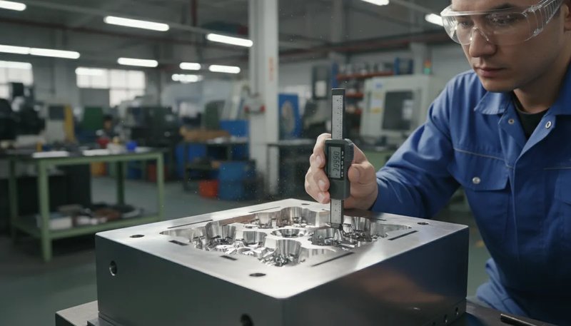
The nozzle tip radius must be 0.5 mm smaller than the sprue bushing radius. A 1 mm mismatch in diameter sounds trivial, but it causes drool, stringing, and cold slugs in the runner. We check nozzle alignment every mold change — it takes 30 seconds with a height gauge and saves hours of defects.
For mixing-sensitive materials (masterbatch color changes, flame retardant blends), consider adding a static mixer between the barrel and nozzle. It adds 50 mm to the melt path but cuts color streak defects by roughly 60%. The trade-off is a slight increase in pressure drop — about 10–15 bar — which you compensate by raising injection pressure.
Nozzle maintenance is one of those tasks that gets skipped when production is busy. But a nozzle with carbonized residue buildup changes the effective orifice diameter, which changes shear rate and melt temperature at the gate. We schedule nozzle pulls and cleaning every 3,000 cycles for engineering resins, every 5,000 for commodity materials.
Why Does Back Pressure Make or Break Melt Quality?
Esta sección trata sobre cómo la contrapresión hace o rompe la calidad de la fusión y su impacto en el costo, la calidad, el tiempo o el riesgo de abastecimiento. La contrapresión es el ajuste único más subestimado en una máquina de moldeo por inyección — controla directamente la homogeneidad de la fusión, la consistencia del color y la estabilidad del peso de disparo a disparo. Para la mayoría de las resinas de ingeniería, el rango óptimo es de 5–15 bar. Demasiado baja (0–3 bar) y se obtienen gránulos no fundidos, remolinos de color y peso de disparo inconsistente. Demasiado alta (25+ bar) y se obtiene una duración del ciclo3, excessive shear heat, and accelerated screw wear.
The practical range for most engineering resins is 5–15 bar. Start at 8 bar, shoot an air shot, and check for consistent extrusion. If the melt looks milky or has visible pellets, increase in 2-bar increments. For PC or PEEK, you may need 12–18 bar because of their high viscosity.
One mistake we see often: operators increasing back pressure to compensate for a worn screw. That works temporarily but the real fix is a screw and barrel inspection. If your cushion is drifting and the recovery time keeps lengthening, the screw flight is probably worn beyond 0.5 mm clearance. At that point, no amount of back pressure adjustment will restore process consistency.
Another subtle issue: back pressure interacts with screw decompression (suck-back). If you run high back pressure and then apply aggressive suck-back, you can pull air bubbles into the melt. The fix is simple — either reduce back pressure slightly, or reduce suck-back distance to 2–3 mm. On vented-barrel machines running hygroscopic resins, this combination is especially important to control.
“Increasing back pressure from 3 bar to 10 bar can reduce color swirl defects by over 50% in ABS parts.”Verdadero
Higher back pressure improves dispersion of colorant in the melt by forcing the material through tighter clearances between screw flights and barrel wall, producing more consistent pigmentation throughout the shot volume.
“Higher back pressure always produces better part quality.”Falso
Excessive back pressure (above 20 bar for most resins) generates too much shear heat, degrades the polymer chains, increases cycle time due to longer screw recovery, and accelerates screw and barrel wear. The optimum is material-specific and typically between 5 and 15 bar.
How Does Screw Speed Affect Plasticizing and Part Consistency?
La velocidad del husillo determina directamente la uniformidad de la temperatura de fusión y la consistencia del color — para la mayoría de las máquinas, 50–100 rpm es el rango óptimo. Una rotación más rápida genera más calor por fricción pero produce una fusión menos uniforme; una rotación más lenta da una mejor mezcla pero puede no terminar la recuperación antes de que el molde se abra. La clave es ajustar la velocidad del husillo para que la recuperación termine 1–2 segundos antes de que el molde se abra.
The rule of thumb: adjust screw speed so that recovery finishes 1–2 seconds before mold open. If the screw is still recovering when the mold opens, you are losing cooling time and creating unnecessary pressure on the operator. If recovery finishes way before mold open, you can slow the screw and reduce shear heating.
Different materials demand different screw speeds. PVC and PMMA are shear-sensitive — keep screw speed below 60 rpm to prevent degradation. POM and PA66 can tolerate 80–120 rpm. PEEK and LCP, despite their high melt temperatures, actually benefit from moderate screw speed (40–80 rpm) because their low viscosity means less shear heating is needed.
Screw speed also affects color consistency. At very low speeds (120 rpm on small machines), you can get localized overheating that causes color streaks or burns. The middle ground, combined with proper back pressure, gives the best results for both melt quality and color uniformity.

What Is Screw Cushion and Why Must It Stay Constant?
Screw cushion² is the small pad of melt left in front of the screw at the end of injection. On small machines, target 3 mm. On large machines (1000T+), target 6–9 mm. The exact number matters less than consistency — if your cushion swings by 2 mm shot to shot, your part weight will fluctuate and dimensions will drift.
Modern machines can hold cushion to ±0.1 mm. If you see ±1 mm variation, check for: (1) non-return valve leakage, (2) inconsistent feed, (3) worn barrel in the metering zone. In our shop, cushion consistency is the first thing we check when a customer reports dimensional variation on a part that used to run fine.
Screw retraction (suck-back) is related but different. After injection and before mold opening, the screw pulls back slightly to decompress the melt and prevent nozzle drool. Typical suck-back is 3–5 mm. On vented barrels running hygroscopic materials, reduce suck-back to 2 mm — pulling air into the melt creates bubbles that appear as splay on the part surface.
When setting cushion, remember: the cushion value you program into the machine controller assumes the screw zero point is correct. After a screw pull and cleaning, always re-zero the screw position. We have seen cases where a 3 mm cushion was actually 0 mm because the zero point shifted during reassembly — resulting in no holding pressure transfer and 100% short shots on the first setup attempt.
How Do You Calculate and Verify Plasticizing Capacity?
¿Cuánta holgura de tornillo debo mantener?
Use this formula: tmin = (total shot weight in g × 3600) ÷ (plasticizing rate in kg/h × 1000). If your actual cycle time is shorter than tmin, the machine cannot melt material fast enough — you will see inconsistent viscosity, short shots on later cavities, and surface gloss variation across the shot.
This is especially critical for multi-cavity molds with high shot weights. If your calculation shows you are at 85% or more of plasticizing capacity, you should either extend cooling time, reduce cavities, or move to a larger machine. Running at the edge of plasticizing capacity is a recipe for scrap.
Another consideration: plasticizing capacity degrades over the life of the machine. A worn screw with increased flight clearance cannot generate the same shear and compression as a new one. If you notice that parts from an older machine consistently show more color variation or unmelt than the same mold on a newer machine, have the screw and barrel measured. Wear of 0.3–0.5 mm on flight diameter can reduce effective plasticizing capacity by 15–25%.

Why Is Melt Temperature Management Critical?
The barrel temperature settings on your machine are not the melt temperature. They are heater band setpoints. The actual melt temperature is affected by screw speed, back pressure, shot volume, and residence time⁵. The only reliable way to know your melt temperature is to measure it at the nozzle with a pyrometer or by air-shot method.
For air shots, wear heat-resistant gloves and a face shield. Extrude a small amount of melt into a metal container and insert a preheated thermocouple probe. The reading should be within ±5 °C of the material supplier’s recommended range. If it is 10–15 °C higher, your shear heating from screw speed and back pressure is adding too much energy — reduce one or both.
Temperature profiling matters too. Set the rear zone (feed) coolest to prevent premature melting and bridging. Increase progressively toward the nozzle. The nozzle tip can be set 5–10 °C lower than the front zone to prevent drool. If you have no experience with a particular resin, always start at the lowest recommended temperature and work up in 5 °C increments.
En ZetarMold, nuestra fábrica de Shanghai opera 47 máquinas de moldeo por inyección que van desde 90T hasta 1850T. Con más de 20 años de experiencia en moldeo desde 2005 y 8 ingenieros senior de moldes en plantilla, estandarizamos la verificación de la temperatura de fusión como parte de cada configuración de producción — antes de la aprobación de la primera pieza, el operador debe confirmar que la temperatura real de fusión en la boquilla esté dentro de ±5 °C de la hoja de proceso.
“Measuring melt temperature by air shot is more accurate than relying on barrel heater setpoints.”Verdadero
Barrel thermocouples are embedded in the steel wall and measure steel temperature, not polymer temperature. Shear heating from screw rotation and back pressure can raise actual melt temperature 10–30 °C above the barrel setpoint, making direct measurement essential for process control.
“All heater zones should be set to the same temperature for simplicity.”Falso
A proper temperature profile starts cooler at the feed zone to prevent bridging, increases through the transition zone for progressive melting, and may be slightly lower at the nozzle tip to prevent drool. Uniform settings across all zones cause feed problems and inconsistent melting.
What About Residence Time and Material Degradation?
El tiempo de residencia — cuánto tiempo permanece el plástico en el cilindro calentado — es el principal impulsor de la degradación térmica en el moldeo por inyección. Cada polímero tiene un tiempo máximo seguro de residencia a una temperatura dada; si se excede, se produce pérdida de peso molecular, decoloración, generación de gases y piezas debilitadas que pueden pasar la inspección visual pero fallar en servicio.
Calculate it: tresidence = (barrel volume in g × cycle time in s) ÷ (shot weight in g × 300). This gives a rough number. The real number is always longer because material hangs up in dead spots. For precision work, do a color purge test: add colored pellets and time how long until color appears in the shot.
The biggest risk: large barrel machines running small shot weights. If your shot uses less than 30% of barrel capacity, your residence time can easily exceed safe limits. The fix is either use a smaller machine or purge the barrel every 15–20 minutes during extended runs. For materials like POM or PVC that degrade aggressively, shot utilization below 20% should be avoided entirely.
Watch for early degradation signs: silver streaks (splay), light brown or yellowish discoloration, a faint acrid smell at the nozzle, or a gradual decrease in part weight without any process changes. These all point to material breaking down in the barrel. When you see them, stop and purge immediately — continuing to run degrading material contaminates the barrel and makes the problem worse for subsequent shots.
How Should Mold Temperature Be Controlled?
Esta sección trata sobre el control de la temperatura del molde y su impacto en el costo, la calidad, el tiempo o el riesgo de abastecimiento. La temperatura del molde debe verificarse con un termómetro de contacto en la superficie de la cavidad — nunca confiar en la pantalla del termorregulador, que puede diferir en 5–15 °C. Para piezas de tolerancia estrecha, mantenga la variación dentro de ±2 °C usando termorreguladores individuales por circuito. La temperatura del molde controla directamente el acabado superficial, la cristalinidad, la contracción y el alabeo.
Always verify mold temperature with a contact thermometer on the cavity surface, not by reading the thermolator display. The display shows coolant temperature at the unit, which can differ from the actual cavity surface by 5–15 °C depending on circuit length, flow rate, and scale buildup inside the channels.
For tight-tolerance parts, keep mold temperature variation within ±2 °C. On our floor, this means using individual thermolators per mold circuit for critical molds — not daisy-chaining multiple circuits to one unit. Yes, it costs more in equipment. But rework and scrap from dimensional drift cost even more, especially on multi-cavity molds where one circuit running 5 °C hotter shifts half the cavities out of spec.
A common mistake: setting mold temperature based on what worked for a similar material on a different mold. Mold size, circuit layout, and wall thickness all affect what temperature the cavity surface actually reaches. A 60 °C setting on a small, simple mold might produce 55 °C at the surface, while the same setting on a large mold with long cooling circuits might only reach 42 °C. Measure every mold, every time.
Why Is Uniform Cooling More Important Than Fast Cooling?
Un enfriamiento uniforme es más importante que un enfriamiento rápido porque las compensaciones de costo, calidad, volumen y aplicación lo respaldan. La mayoría de los operadores intentan enfriar el molde lo más rápido posible para reducir complete injection mold design guide. Speed matters, but uniformity matters more. Uneven cooling causes differential shrinkage, which causes warpage, internal stress, and out-of-tolerance dimensions — even if the cycle time looks great on paper.
The counterintuitive technique: run cooler water on the core (inside of the part) and warmer water on the cavity (outside). This equalizes the cooling rate between thick and thin sections. For flat, precision parts — think optical lenses, sealing surfaces, or mating housings — this alone can cut warpage by 40–60%.
Check cooling circuit flow rate at every mold change. A circuit that flowed 12 L/min last run might be down to 4 L/min because of scale buildup. Low flow means turbulent flow becomes laminar, heat transfer drops by 30–50%, and your carefully set temperatures become meaningless. If flow drops below 60% of original, clean or replace the circuit before running production.
For multi-cavity molds, balancing cooling across cavities is critical. The cavity closest to the water inlet always cools fastest. Use flow restrictors or individual circuits per cavity to equalize cooling. On eight-cavity molds, we have measured 8 °C temperature difference between the first and last cavity on a single series circuit — enough to produce measurable dimensional variation between parts.
What Are the Most Overlooked Tips for Injection Moulders?
The most overlooked tips for injection moulders are the main categories or options explained in this section. Beyond the five core settings, several secondary factors catch people off guard on a regular basis:
Tip 14: Check the non-return valve. The ring-type check valve at the screw tip wears gradually. When clearance exceeds 0.1 mm, you lose holding pressure consistency. Inspect every 500,000 shots or whenever cushion variation exceeds ±0.5 mm. A replacement non-return valve costs a few hundred dollars; running production with a worn one costs thousands in scrap.
Tip 15: Vent the mold properly. Trapped air causes burning, dieseling, and short shots in dead-end areas. Vents should be 0.01–0.02 mm deep at the parting line and clean — not polished shut from previous flash. Add vent pins at the end of flow paths and at blind pockets where air naturally traps.
Tip 16: Dry the material correctly. Hygroscopic resins (PC, Nylon, PET, TPU) absorb moisture that causes splay, molecular degradation, and weakened weld lines. PC needs drying at 120 °C for 3–4 hours with dew point below –20 °C. A material that ‘looks dry’ is not dry — verify with a moisture analyzer before every production run.
Tip 17: Record everything. Every parameter change, every temperature reading, every cavity dimension on the first 10 shots. When problems appear on day 3 of production, you will need that baseline. We require all operators to fill out a setup log before first article approval. The 10 minutes spent on documentation saves hours of finger-pointing later.
Tip 18: Trust the data, not intuition. If the process sheet says 240 °C melt and 60 °C mold, and the parts look good — do not ‘optimize by feel’ on the next run. Documented, repeatable process windows beat operator judgment every time. That is how you get consistent quality across 120+ production workers on multiple shifts.
What Are the Most Frequently Asked Questions About Injection Molding Tips?
What is the ideal back pressure for injection molding?
La contrapresión ideal para la mayoría de las resinas de ingeniería es de 5–15 bar. Comience en 8 bar para materiales de uso general como ABS y PP. Aumente a 12–18 bar para resinas de alta viscosidad como policarbonato o PEEK. Exceder los 20 bar proporciona rendimientos de calidad decrecientes mientras acelera el desgaste del husillo y extiende el tiempo de ciclo. Verifique siempre el resultado con una prueba de disparo al aire. En nuestras 47 máquinas que ejecutan más de 400 materiales, encontramos que mantener la contrapresión entre 8–12 bar cubre aproximadamente el 80% de los trabajos de producción sin problemas.
How much screw cushion should I maintain?
18 Consejos Importantes para Moldeadores por Inyección — Guía Práctica
How do I verify actual melt temperature?
Use the air-shot method with a preheated pyrometer probe. Extrude a small melt sample into a metal container wearing heat-resistant gloves and a face shield, then insert the probe immediately. The reading should be within ±5 °C of the material datasheet range. Barrel heater setpoints are not reliable melt temperature indicators because shear heating from screw rotation can raise actual temperature 10–30 °C above setpoints. For critical jobs, we recommend taking air-shot readings at the start of each shift and after any speed or back pressure change.
Why are my injection molded parts warping?
Warping occurs when cooling rate variation exceeds 15 °C across the part, typically from non-uniform wall thickness exceeding a 3:1 ratio or inadequate cooling circuit design. Fix cooling uniformity first by running cooler water on the core side and warmer water on the cavity side. This differential cooling technique reduces warpage by 40–60% on flat precision parts without changing cycle time significantly. Also check that gate placement supports balanced fill — asymmetric filling creates internal stresses that amplify warpage even when cooling is uniform.
How often should injection molding nozzles be inspected?
Inspect open nozzles every mold change for alignment and tip radius wear — the tip radius should be 0.5 mm smaller than the sprue bushing radius. Inspect shut-off (closed) nozzles every 2,000 cycles for valve seating integrity. Schedule nozzle pulls and cleaning every 3,000 cycles for engineering resins and every 5,000 cycles for commodity materials to prevent carbonized residue buildup. During peak production months, our team pulls nozzles weekly on machines running glass-filled nylon, as abrasive wear accelerates significantly with filled compounds.
What happens if residence time is too long in the barrel?
Excessive residence time causes thermal degradation: molecular weight drops, discoloration appears (yellow or brown tint), gas generation increases, and mechanical properties decline. The risk is highest when shot weight uses less than 30% of barrel capacity. Purge the barrel every 15–20 minutes during such runs, or move to a smaller machine. Watch for early signs like silver streaks or acrid smell. Calculate residence time using barrel volume divided by shot volume multiplied by cycle time — if it exceeds 5 minutes for most engineering resins, you are in the degradation zone.
How do I calculate if my machine has enough plasticizing capacity?
Divide total shot weight in grams by 1000, multiply by 3600, then divide by the machine’s rated plasticizing capacity in kg/h. The result is your minimum cycle time in seconds. If your actual cycle time is shorter than this calculated minimum, the machine cannot melt material fast enough for consistent quality — you will see viscosity variation and surface defects. Always include a 10–15% buffer above the calculated minimum to account for material batch variation and ambient temperature changes that affect real-world throughput.
Should all mold cooling circuits use the same water temperature?
No. For parts with significant wall thickness variation, use differential cooling: cooler water (10–15 °C lower) on the core and warmer water on the cavity side. This equalizes cooling rates between thick and thin sections, reducing warpage by 40–60%. For multi-cavity molds, use individual circuits per cavity or flow restrictors to balance cooling across all cavities. At our Shanghai facility, we verify cooling circuit flow rates at every mold change using a flow meter — a circuit flowing below 80% of its design rate gets descaled or replaced before production starts.
-
back pressure: Back pressure is the resistance applied to the screw during its recovery stroke, measured in bar or MPa, which controls melt homogeneity and mixing quality in the injection cylinder. ↩
-
cushion: Cushion, also called screw cushion or pad, refers to the small volume of molten plastic remaining in front of the screw tip at the end of injection, typically 3–9 mm, ensuring consistent pressure transfer to the cavity. ↩
-
cycle time: Cycle time is the total elapsed time from the start of one injection molding shot to the start of the next, measured in seconds, encompassing injection, holding, cooling, and ejection phases. ↩


