 콘텐츠로 건너뛰기

첫 생산 샘플을 받아보았는데, 부품이 금형에 달라붙고 있습니다. 이젝터 핀 자국이 남고, 일부 부품에는 측면을 따라 긁힌 자국이 있습니다. 금형 제작자는 데프트 각도를 더 늘려야 한다고 말합니다. CAD 도면이 깔끔해 보여서 데프트를 0으로 요청했던 터입니다. 이제 12,000톤 용량의 $ 금형을 수리해야 합니다. 좋은 소식은 금형 제작 전에 데프트 각도를 이해한다면 가장 쉽게 예방할 수 있는 문제 중 하나라는 점입니다.
이 글은 구배 각도1 중요한 이유, 재료와 질감에 따른 표준 값, 그리고 실제 생산 과정에서 제가 목격한 실수로 인해 실제 돈이 소모된 사례를 다룹니다.
- 대부분의 연마된 표면에 대해 표준 드래프트는 측면당 1~2도입니다.
- 질감 표면은 질감 등급마다 1~1.5도 추가 데프트가 필요합니다.
- 제로 드래프트는 가능하지만 위험하며, 생산에서는 거의 가치가 없습니다.
- 드래프트는 금형 작업 시작 전에 적용해야 합니다 — 재작업은 비용이 많이 듭니다.
- 수축률, 재료, 벽 두께 모두 필요한 최소 드래프트에 영향을 미칩니다.
사출 성형에서 드래프트 각도란 무엇인가요?
A 사출 성형 드래프트 각도는 금형 캐비티의 모든 수직 표면에 의도적으로 부여된 테이퍼입니다. 부품이 냉각되어 코어에 수축한 후 자유롭게 미끄러져 나올 수 있도록 벽에 약간의 기울기를 추가한 것이라고 생각하세요. 이것이 없으면 부품이 진공 밀봉처럼 강철을 꽉 잡고, 이젝션은 이젝터 핀과 금형 표면 사이의 싸움이 됩니다.
드래프트 각도는 금형 개방 방향의 수직축에서 도 단위로 측정됩니다. 1도의 드래프트는 벽이 깊이 1mm당 약 0.0175mm 바깥쪽으로 기울어진다는 의미입니다. 깊이 50mm의 포켓에서는 상단에서 측면당 약 0.87mm의 간격을 제공합니다. 작게 들리지만, 깨끗한 배출과 끼인 부품의 차이입니다.
부품의 모든 수직 표면에는 드래프트가 필요합니다. 여기에는 외부 벽, 내부 리브, 보스, 포켓, 심지어 스루홀도 포함됩니다. 표면이 금형 개방 방향과 평행하게 배치되고 테이퍼가 없으면, 부품이 이젝션 중에 끌리면서 스크래치, 긁힘 또는 뒤틀림이 발생합니다.

드래프트 각도가 부품 품질에 중요한 이유는 무엇인가요?
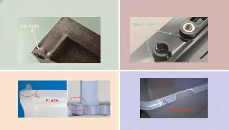
이 섹션은 데프트 각도가 부품 품질에 미치는 영향과 비용, 품질, 시기, 조달 리스크에 대한 영향을 다룹니다. 데프트 각도는 부품 외관, 치수 정확도, 금형 수명, 사이클 타임 네 가지에 직접 영향을 미칩니다. 부품이 금형에 달라붙으면 사출 금형 배출 시스템2 더 많은 힘을 써야 합니다. 이젝터 핀 자국이 남고, 부품 표면에 끌림 자국이 생깁니다. 최악의 경우 부품이 떨어지기 전에 갈라지거나 변형됩니다.
불충분한 드래프트는 또한 금형 마모를 가속화합니다. 매 사이클마다 부품이 이젝션 중에 캐비티 벽을 긁습니다. 100,000회 이상의 사이클 동안 지속적인 마찰은 강철 표면을 연마하고 긁힘 자국을 남깁니다. 500,000회까지 지속되어야 할 금형이 200,000회에서 연마나 재작업이 필요할 수 있습니다.
생산 측면에서, 배출이 어려운 부품은 사이클을 느리게 만듭니다. 작업자가 부품을 수동으로 두드려 빼내야 하거나, 로봇이 부품을 잡는 데 어려움을 겪는다면 사이클당 몇 초씩 손실됩니다. 규모가 커지면, 이는 실제 돈으로 이어집니다. 30초 사이클에 3초 지연은 10%의 생산 능력 손실입니다.
“A 1-degree draft angle can reduce ejection force by up to 50% compared to zero draft.”True
테이퍼는 수축하는 플라스틱과 금형 코어 사이의 진공 효과를 깨뜨립니다. 아주 작은 각도라도 이젝션 시 마찰 계수를 극적으로 낮춰 이젝터 시스템이 필요로 하는 힘을 줄입니다.
“If the mold has enough ejector pins, you do not need draft angle.”False
이젝터 핀이 많을수록 힘 분산이 잘 되지만, 평행 벽면과 수축하는 플라스틱 사이의 근본적인 마찰을 극복할 수는 없습니다. 데프트가 없으면 핀은 단지 더 작은 면적에 힘을 집중시켜 핀 자국과 부품 변형 위험을 증가시킵니다.
표준 데프트 각도 값은 무엇인가요?
단 하나의 정확한 드래프트 각도는 없습니다 — 재료, 표면 마감, 깊이, 공차 요구사항에 따라 달라집니다. 하지만 수천 개의 생산 금형에서 실제로 효과가 입증된 값들은 다음과 같습니다.
| 표면 마감 | 최소 데프트 | Recommended Draft | 참고 |
|---|---|---|---|
| Polished (SPI A-1 to A-3) | 0.5° | 1° | 매끄러운 표면은 쉽게 분리됩니다 |
| 표준 (SPI B-1 ~ B-3) | 1° | 1.5° | 가벼운 가공 자국 |
| 미세 질감 (VDI 12-24) | 1° | 1.5° ~ 2° | 텍스처 깊이 등급당 1° 추가 |
| 중간 텍스처 (VDI 27-33) | 1.5° | 2° ~ 3° | 텍스처가 부품 표면에 고정됩니다 |
| 거친 텍스처 (VDI 36-45) | 2° | 3° ~ 5° | 깊은 그레인은 미세 언더컷처럼 작용합니다 |
| 완성된, 제로 드래프트 | 0° | 권장되지 않음 | 10mm 미만의 얕은 구조에만 적용 |
제가 사용하는 경험 법칙: 광택 표면은 측면당 1도부터 시작하고, 질감 등급이 올라갈 때마다 1도를 추가하며, 10mm보다 깊은 부품에는 절대 0.5도 미만으로 내려가지 않습니다. 고객이 치수 제약으로 데프트에 반대한다면, 0.5도 테이퍼 적용 비용과 수리 비용을 계산하여 보여주세요.
리브와 보스와 같은 내부 형상의 경우 드래프트 상황이 더 중요합니다. 플라스틱은 냉각 중 코어에 수축하여 단단한 잡아당김을 만듭니다. 리브는 측면당 최소 0.5도 이상이어야 하지만, 1도가 더 안전합니다. 보스는 외부에 최소 0.5도가 필요하며, 내부 홀도 코어 핀에 의해 형성되는 경우 드래프트가 적용되어야 합니다.
재료 수축이 드래프트 요구 사항에 어떤 영향을 미치나요?
수축3 드래프트가 처음부터 존재하는 이유입니다. 플라스틱이 금형 내에서 냉각되면 수축합니다. 부품이 컵이나 상자 모양이면, 그 수축이 벽을 금형 코어에 단단히 당깁니다. 수축률이 높을수록 잡아당김은 더 강해지며, 더 많은 드래프트가 필요합니다.
| 재료 | 수축률 | Min Draft (Polished) | 최소 데프트 (질감 표면) |
|---|---|---|---|
| ABS | 0.4–0.7% | 0.5° | 1.5° |
| 폴리카보네이트(PC) | 0.5–0.7% | 0.5° | 1.5° |
| 나일론 6 (PA6) | 0.5–1.5% | 1° | 2° |
| 나일론 66 (PA66) | 0.8–2.0% | 1° | 2.5° |
| Glass-Filled Nylon | 0.2–0.8% | 0.5° | 1.5° |
| PP(폴리프로필렌) | 1.0–2.5% | 1° | 2.5° |
| PE(폴리에틸렌) | 1.5–3.0% | 1.5° | 3° |
| POM (Acetal) | 1.5–2.5% | 1° | 2.5° |
| PBT | 0.8–2.0% | 1° | 2° |
Crystalline materials like nylon, PP, and POM shrink more than amorphous materials like ABS and PC. That means they grip the core harder and need more draft. Glass-filled nylon is an exception: the glass fibers reduce shrinkage, so it actually needs less draft than unfilled nylon, even though the fibers make the material more abrasive on the mold.
We once ran a PP housing project where the customer insisted on 0.5-degree draft with a medium texture. The parts stuck on every other cycle. We ended up re-cutting the core to add 1.5 degrees more draft — three weeks of lost production. PP with 2.5 percent shrinkage on a textured surface was never going to work at 0.5 degrees.
What Happens When Draft Is Insufficient?
The symptoms show up immediately on the production floor. Here is what you will see, in order of severity:
First, drag marks. The part surface gets parallel scratches along the ejection direction. On polished parts, this is immediately visible and rejects the part cosmetically. On textured parts, the texture gets polished off in streaks, creating an uneven finish that no amount of post-processing can fix.
Second, ejector pin marks. When the part resists ejection, the pins concentrate force on small areas. You get white stress marks on the inside, visible pin push marks, or even pin-through holes if the wall is thin. In our shop, we consider any pin mark deeper than 0.1 mm a reject for visible surfaces.
Third, part distortion. If the part does release but with high ejection force, it can warp, bow, or crack. Thin-walled parts are especially vulnerable. The force needed to push a zero-draft part out of a deep cavity can exceed the structural strength of the wall, causing permanent deformation.
Fourth, mold damage. Over time, the constant high-force ejection wears ejector pin holes, scores cavity surfaces, and can crack cores. A mold running zero-draft deep pockets might need pin replacement every 50,000 cycles instead of every 200,000. That is four times the maintenance cost.
“Adding 1 degree of draft to a textured surface can eliminate ejection drag marks completely.”True
The additional taper creates clearance between the shrinking plastic and the textured steel surface. This clearance breaks the mechanical interlock between the texture pattern and the solidified part surface, allowing clean release.
“Draft angle only matters for cosmetic parts — structural parts do not need it.”False
Draft is a mechanical requirement, not just a cosmetic one. Structural parts face the same shrinkage and friction forces during ejection. In fact, structural parts with tight tolerances are even more sensitive to ejection-induced warpage caused by insufficient draft.
How Do Texture and Surface Finish Change Draft Requirements?
This is where most draft problems originate. A polished mold surface is essentially smooth — the part slides out with minimal friction. But a textured surface has microscopic peaks and valleys that act like tiny undercuts. As the plastic shrinks, it wraps around those peaks, creating a mechanical lock that resists ejection.
The industry standard rule: add 1 degree of draft per 0.01 mm of texture depth. Most texture suppliers rate their patterns on a scale from fine to coarse. A fine sandblast texture might be 0.01 mm deep and only need 1 extra degree. A deep leather grain could be 0.05 mm deep and need 5 extra degrees on top of the base draft.
If you are specifying a texture on your part, always tell your toolmaker before the mold is cut. Changing the surface finish after tooling often means re-cutting the cavity to add draft, which is expensive and can affect the part dimensions. We had a case where a customer added a VDI-33 texture to a mold that was designed for a polished finish with 1 degree draft. The mold had to be pulled, the cavity re-cut to 3.5 degrees, and re-polished. Six weeks of downtime.
How to Calculate Draft Angle for Your Part?
The basic calculation is straightforward. Draft clearance equals the tangent of the draft angle multiplied by the depth of the feature:
Clearance per side = tan(draft angle) x depth
For example, a 1-degree draft on a 50 mm deep wall gives: tan(1°) x 50 = 0.0175 x 50 = 0.87 mm clearance per side. At 2 degrees, it is 1.75 mm per side. At 3 degrees, 2.62 mm per side.
The practical question is not the math — it is whether your part can tolerate that much size variation from bottom to top. For most enclosures and housings, 1 to 2 mm of taper across a 50 mm wall is invisible to the end user. But for precision components like gears, bearing seats, or mating interfaces, you may need to hold tighter draft or use alternative ejection strategies.
| Depth (mm) | 0.5° Draft | 1° Draft | 1.5° Draft | 2° Draft | 3° Draft |
|---|---|---|---|---|---|
| 10 | 0.09 | 0.17 | 0.26 | 0.35 | 0.52 |
| 25 | 0.22 | 0.44 | 0.65 | 0.87 | 1.31 |
| 50 | 0.44 | 0.87 | 1.31 | 1.75 | 2.62 |
| 75 | 0.65 | 1.31 | 1.96 | 2.62 | 3.93 |
| 100 | 0.87 | 1.75 | 2.62 | 3.49 | 5.24 |
Notice that even a small depth of 10 mm with 0.5 degrees only gives you 0.09 mm of clearance. That is barely enough to overcome surface friction, especially if there is any texture. This is why most toolmakers push back on anything below 1 degree — the margin for error is too thin.
What Are Common Draft Angle Mistakes?
Common draft angle mistakes are the main categories or options explained in this section. After 20 years of building molds, the same mistakes come up over and over. Here are the ones that cost the most money:
Mistake 1: Applying draft only to outside walls. Inside features like ribs, bosses, and gussets are often forgotten. These surfaces shrink onto the core just like outside walls, but they are harder to eject because the ejector pins cannot reach them directly. Every rib needs at least 0.5 degrees per side. Every boss needs at least 0.5 degrees outside.
Mistake 2: Opposing draft directions. If you draft the cavity side one way and the core side the other, the part gets thicker at one end and thinner at the other. This creates uneven wall thickness that causes warpage and sink marks. All draft on a given feature should converge toward the parting line so wall thickness stays consistent.
Mistake 3: Ignoring draft on shut-off surfaces. When a through-hole or window is formed by both halves of the mold meeting, the shut-off surface needs draft too. Without it, the steel-on-steel contact area acts as a brake during mold opening. We have seen molds where the press had to be cranked up 20 percent in tonnage just to overcome shut-off friction from zero-draft horizontal surfaces.
Mistake 4: Not accounting for post-mold texture. Some customers plan to add texture after molding through painting or pad printing. If the draft was calculated for a polished surface and the post-process adds thickness, the effective clearance drops. Always design for the final surface condition, not the as-molded condition.
Mistake 5: Zero draft on deep pockets. This is the single most expensive mistake. Deep pockets with zero draft almost always cause ejection problems. If the design absolutely cannot have draft, plan for a split core or collapsible core from the start. It costs more up front but avoids the rework bill later.
How to Handle Draft on Complex Part Geometries?
Not every part is a simple box with straight walls. Real production parts have undercuts, side features, angled holes, and asymmetric geometry. Here is how to handle draft in the common complex scenarios.
Angled surfaces. If a wall is already angled more than the required draft, you do not need to add more. A wall that leans 5 degrees from vertical already has 5 degrees of draft. Only add draft if the surface is closer to vertical than the minimum requirement.
Ribs and gussets. Draft ribs from the base to the tip. The base is the thickest part and where the rib meets the wall. The tip is the thinnest. A typical rib has 0.5 to 1 degree per side, which naturally makes the tip thinner. Make sure the tip does not get thinner than 0.5 mm, or it will not fill properly.
Threads and undercuts. External threads formed in the cavity need draft on the thread flanks, which changes the thread profile. This is why most production threaded parts use threaded inserts or unscrewing cores instead of direct molded threads. If you must mold threads, work with your toolmaker to validate the thread gauge will still fit after draft is applied.
Louver and vent patterns. These features have thin vanes that need draft on both sides. Because they are thin and deep, they are ejection trouble spots. Use a minimum of 1 degree per side, and specify polished surfaces on the mold for these features.
What Draft Angle Should You Specify in Your Mold Design?
Here is the decision framework I use when reviewing a mold design for draft adequacy. It works for 95 percent of production parts:
Step 1: Identify every surface that is parallel to the mold opening direction. Mark them in your CAD system with a color code. Red for zero draft, yellow for marginal draft (0.5 degrees or less), green for adequate draft (1 degree or more).
Step 2: For each red or yellow surface, determine the surface finish. Polished surfaces can get away with less draft. Textured surfaces need more. Check with your texture supplier for their recommended draft per pattern.
Step 3: Check the material shrinkage. Cross-reference the shrinkage rate with the draft table above. Higher shrinkage means you need more draft to overcome the grip on the core.
Step 4: Verify wall thickness is consistent from bottom to top. If adding draft makes the wall too thick or too thin at one end, adjust the part geometry to compensate. Moving the parting line or changing the wall profile are usually the easiest fixes.
Step 5: Review with your toolmaker before cutting steel. A 30-minute design review can save weeks of rework. Your toolmaker knows which features are ejection trouble spots from experience.
In our factory, our engineers review every mold design for draft adequacy before machining begins. Our team checks ribs, bosses, textured sidewalls, and ejection direction against the DFM record, so draft-related rework stays below 1% across 100+ mold sets delivered per month from our Shanghai factory.
That is why our team treats draft angle as a production-risk review item, not a cosmetic CAD preference. Our engineers mark any zero-draft or marginal-draft surface before steel cutting, then confirm the customer can accept the small taper before machining starts.
자주 묻는 질문
What is the minimum draft angle for injection molding?
The minimum draft angle is 0.5 degrees per side for polished surfaces on low-shrinkage materials like ABS or PC. For textured surfaces or high-shrinkage materials like PP or nylon, the practical minimum is 1.5 to 2 degrees. Anything less than 0.5 degrees is extremely risky and should only be attempted on shallow features under 10 mm depth with polished mold surfaces and robust ejection systems. In production environments, most experienced toolmakers will not recommend going below 1 degree on any surface deeper than 15 mm regardless of finish or material.
Can you injection mold without draft angle?
Technically yes, but it is almost never recommended for production runs. Zero draft is possible on very shallow features under 10 mm with polished mold surfaces and low-shrinkage materials. For anything deeper, zero draft will cause ejection drag marks, pin push, part warpage, and accelerated mold wear that dramatically shortens tool life. If your design absolutely requires zero draft, plan for alternative ejection methods like air blasts, stripper plates, or collapsible cores from the start. These alternatives add cost and complexity but are necessary to avoid production problems.
How much draft do you need for textured injection molded parts?
The standard rule is 1 degree of draft per 0.01 mm of texture depth. A fine texture rated VDI 12 to 24 typically needs 1 to 1.5 degrees of additional draft on top of the base 1 degree. Medium textures need 2 to 3 degrees total per side. Heavy textures like leather grain may require 3 to 5 degrees total per side. Always confirm with your texture supplier, as their specific pattern depth determines the exact requirement. Failing to add sufficient draft for texture is one of the most common and expensive mold design mistakes in the industry.
Does draft angle affect part tolerances?
Yes, draft angle changes the part dimensions from bottom to top of the drafted surface, and this effect must be accounted for in tolerance specifications. On a 50 mm deep wall with 1 degree of draft, the top of the wall is approximately 0.87 mm wider per side than the bottom. For most cosmetic parts, this taper is invisible to the user. For precision parts with mating surfaces, you need to control which end of the draft holds the critical dimension and clearly communicate this to your toolmaker in the tolerance specification to avoid assembly issues.
What is the difference between draft angle and taper?
In injection molding context, draft angle and taper refer to the same geometric feature, which is defined as the intentional lean applied to vertical surfaces for part ejection. Draft angle is the standard term used in mold design and is measured in degrees from the mold opening direction. Taper is sometimes used in machining contexts and may be expressed as a ratio such as 1 to 50. For practical purposes in mold design discussions, they are interchangeable, but it is always best practice to specify values in degrees to avoid confusion between design and manufacturing teams.
How do you add draft to ribs and bosses?
Ribs should be drafted from the base where they meet the wall out to the tip. Use 0.5 to 1 degree per side, and ensure the tip does not get thinner than 0.5 mm to avoid fill problems during molding. Bosses need draft on the outside surface at a minimum of 0.5 degrees, and the inside hole also needs draft if it is formed by a core pin. For bosses taller than 15 mm, consider increasing draft to 1 degree per side to ensure reliable ejection. Always verify that rib and boss draft directions are consistent with the main wall draft to maintain uniform wall thickness throughout the part.
What draft angle does glass-filled nylon need?
Glass-filled nylon typically needs 0.5 to 1 degree of draft per side for polished surfaces, and 1.5 to 2 degrees for textured surfaces. The glass fibers reduce shrinkage compared to unfilled nylon, which actually lowers the draft requirement on the shrinkage side. However, glass-filled nylon is abrasive on mold surfaces, so adequate draft helps reduce friction and extend mold life significantly. The fibers do not change the fundamental draft calculation, but the reduced shrinkage means the part grips the core less tightly, giving you slightly more margin on minimum draft values than unfilled nylon would allow.
–text How Should You Apply Draft Angle Knowledge to Your Next Project?
Draft angle is one of those fundamentals that separates a smooth production run from an expensive rework project. The rules are simple: 1 degree per side minimum for polished surfaces, add 1 degree per texture grade, account for material shrinkage, and never cut steel without reviewing every vertical surface for adequate draft.
If you take one thing from this article, let it be this: add draft early, add it generously, and review it with your toolmaker before the mold is cut. It also helps to map draft decisions against the 사출 성형 단계, because draft affects filling, cooling, ejection, and inspection rather than only CAD appearance. The cost of an extra degree of draft at the design stage is zero. The cost of adding it after the mold is built is measured in weeks and thousands of dollars.
Need a mold built right the first time? Use our supplier sourcing guide to check whether a mold maker can review draft angles, DFM risks, and ejection evidence before you commit to tooling.
-
draft angle: A draft angle is the taper applied to the vertical surfaces of a mold cavity, measured in degrees, that allows the molded part to be ejected without friction or damage. ↩
-
이젝션 시스템: An ejection system is defined as the mechanical assembly inside a mold that pushes the cooled part out of the cavity, typically consisting of ejector pins, sleeves, or stripper plates. ↩
-
shrinkage: Shrinkage refers to the dimensional reduction of a plastic part as it cools from melt temperature to room temperature, typically expressed as a percentage of the original mold dimension. ↩


