 콘텐츠로 건너뛰기

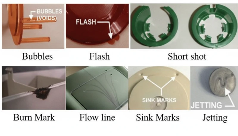
Polycarbonate (PC) is one of the most versatile engineering thermoplastics in 사출 성형—transparent, impact-resistant, and thermally stable. But anyone who has actually run PC on a production line knows it is also one of the most finicky materials to process. Its high melt viscosity, extreme moisture sensitivity, and tendency to trap internal stress mean that even small process deviations can produce visible defects: discoloration, silver streaks, bubbles, flow marks, and stress cracking.
In this article, we walk through the six most common PC molding defects we encounter in production—discoloration and black spots, silver streaks and bubbles, flow marks, cold material spots, and internal stress cracking. For each defect, we explain the physical mechanism, how to diagnose it from the defect pattern, and the specific process and tooling adjustments that resolve it. These insights come from two decades of hands-on PC molding experience across automotive, medical, and consumer electronics applications.
- PC moisture sensitivity (requires <0.02% moisture) is the root cause of most surface defects
- Higher melt viscosity than ABS or PP means PC needs precise temperature and pressure control
- Internal stress in transparent PC parts can cause delayed cracking days after molding
- Most defects share common fixes: proper drying, optimized barrel temperature, and adequate mold venting
- Factory experience with 400+ materials shows that drying discipline alone eliminates 60% of PC defects
What Makes Polycarbonate Injection Molding So Challenging?
Polycarbonate is one of the most difficult engineering thermoplastics to injection mold. Its unique molecular structure—linear chains with benzene rings, isopropylidene groups, and carbonate linkages—creates three core processing challenges that set it apart from easier materials like polypropylene or ABS.
If you are comparing vendors or planning procurement, our injection molding supplier sourcing guide covers RFQ prep, qualification, and commercial risk checks.
First, PC has no sharp melting point. Instead, it gradually softens across a wide temperature range (230–320 °C), which means melt viscosity remains high1 throughout normal processing. Unlike semi-crystalline polymers that thin out dramatically above their melting point, PC behaves more like a Newtonian fluid—its viscosity is more sensitive to temperature changes than to shear rate. Small temperature deviations of just 10–15 °C can push the melt from processable to degraded.
Second, PC is extremely sensitive to moisture. Even trace amounts of water (above 0.02% by weight) cause hydrolytic degradation at processing temperatures, breaking polymer chains and reducing mechanical properties. This means thorough predrying at 120 °C for 3–4 hours is mandatory—not optional. In our experience processing over 400 materials at the Shanghai factory, moisture-related defects account for roughly 60% of all PC molding problems we troubleshoot.
In our Shanghai factory, with 20+ years of injection molding experience across 400+ plastic materials, we have seen every PC defect pattern imaginable. Moisture control and barrel temperature discipline are the two variables that separate a smooth PC production run from a costly scrap event.
Third, the high viscosity of PC melt means that 사출 금형 design must accommodate higher injection pressures, larger gates and runners, and deeper exhaust grooves than what you would need for commodity plastics. Under-sized flow channels create excessive shear heat, which paradoxically causes thermal degradation even when barrel temperatures are set correctly. Understanding these three constraints—high viscosity, moisture sensitivity, and shear sensitivity—is the foundation for preventing every defect covered in this article.
What Causes Discoloration, Yellowing, and Black Spots in PC Parts?
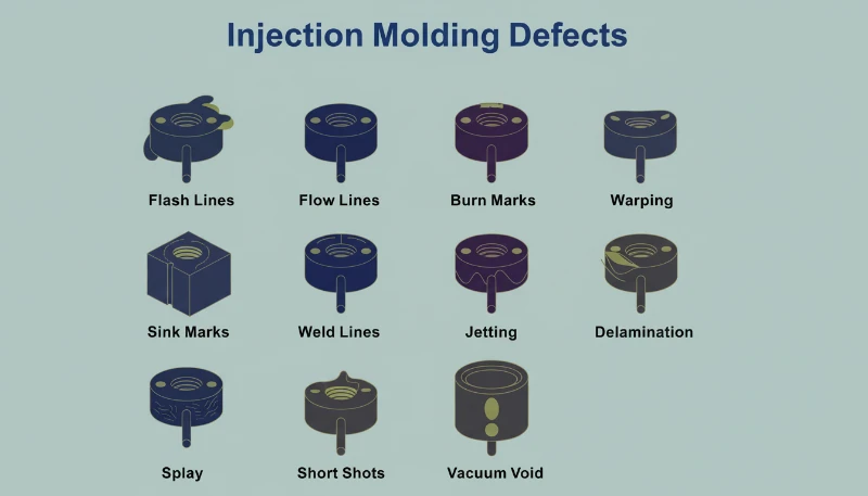
Discoloration is the most common visual defect in PC injection molding, caused by thermal degradation of the melt. The root cause is typically excessive barrel temperature, overly long residence time, or dead zones in the plasticizing system where degraded material accumulates and intermittently releases into the melt stream.
Pure PC resin has excellent thermal stability and can tolerate temperatures up to 300 °C without significant decomposition. The problem arises when processors use modified PC blends, recycled material, or PC compounded with flame retardants and fillers. These additives narrow the processing window considerably. For example, PC/ABS blends typically require barrel temperatures around 250 °C, while PC/PBT blends for lighting products need approximately 280 °C—each combination has its own thermal ceiling that, once exceeded, triggers irreversible yellowing or carbonization.
Black spots are a particularly frustrating variant because they can appear intermittently—sometimes two or three shots in a row, then disappearing. This pattern almost always indicates dead material trapped somewhere in the plasticizing system: screw check ring gaps, nozzle tip interfaces, or barrel wall scoring. The trapped material carbonizes over time, then breaks loose in chunks. When PC decomposition products accumulate beyond a critical threshold, they also catalyze further decomposition, creating a cascading effect—especially severe in flame-retardant grades.
| PC Material Type | Recommended Barrel Temp | Degradation Risk Above |
|---|---|---|
| Pure PC (optical grade) | 270-300 C | 320 C |
| ISO 10993: | 240-260 C | 280 C |
| PC with flame retardant | 230-260 C | 280 C |
| PC/PBT blend (lighting) | 260-280 C | 300 C |
| Recycled PC | 240-270 C | 290 C (variable) |
The fixes are systematic. First, verify barrel temperature setpoints against the material grade and reduce the feed and compression zone temperatures by 5–10 °C increments until discoloration stops. Second, ensure thorough drying: 120 °C for 3–4 hours using a dehumidifying dryer, never exceeding 10 hours to avoid material aging. Third, inspect the plasticizing system for dead zones—remove and clean the nozzle, check ring, and screw if air-shot melt shows discoloration even at correct temperatures. Finally, purge the barrel with a thermally stable material (PS or PE) before and after each production run, and never leave PC sitting at processing temperature during extended stops; drop the barrel to 160 °C (PC glass transition2) or below for thermal holds.
“Lowering barrel temperature is always the first step when PC parts show yellowing.”True
Lowering barrel temperature is the correct first response because excessive heat is the most common cause of PC yellowing. However, if discoloration persists after a 10-15 C reduction, the root cause likely shifts to dead material in the plasticizing system or contaminated raw material.
“Using higher back pressure always improves PC melt quality.”False
Excessive back pressure generates additional shear heat in the barrel, which can accelerate thermal degradation of PC. The correct approach is moderate back pressure (0.5-1.5 MPa) combined with adequate drying and proper barrel temperature profiling.
Why Do Silver Streaks and Bubbles Appear on PC Products?
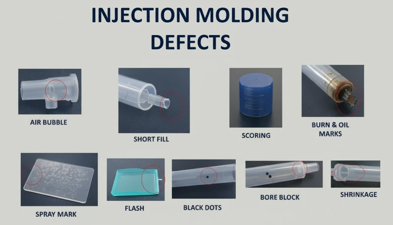
Silver streaks (also called gas streaks) and bubbles are surface and internal defects caused by gas trapped in the melt during cavity filling. In PC injection molding, the four gas sources are water vapor, entrained air, thermal decomposition gas, and solvent gas—water vapor and decomposition gas account for the vast majority of cases.
Silver streaks form when gas dissolved in the pressurized melt escapes to the product surface as cavity pressure drops after filling. The escaping gas leaves tiny elongated bubbles that sparkle under light, always aligned with material flow direction. Bubbles, on the other hand, are gas pockets trapped in the wall thickness—particularly visible in transparent PC parts. Vacuum bubbles are different: they form not from gas but from volumetric shrinkage when insufficient holding pressure leaves a void in thick sections.
How to Diagnose the Gas Source Behind Silver Streaks
Diagnosing which gas is responsible requires reading the defect pattern. Randomly scattered surface bubbles point to water vapor—the most common culprit in PC because the material is so hygroscopic. Fine, dense bubble clusters concentrated near the gate in a radial or fan-shaped pattern indicate entrained air, typically from excessive screw retraction speed or insufficient back pressure. Discoloration accompanying the silver streaks points to decomposition gas from overheated melt. The diagnostic process matters because each gas source requires a different fix.
For moisture-driven silver streaks, the solution is straightforward: ensure drying at 120 °C for 3–4 hours with a dehumidifying dryer. Verify effectiveness by air-shooting—the extruded melt should be continuous, smooth, and free of white vapor. For air entrainment, reduce screw speed, increase back pressure, and extend melt time during the cooling phase. For decomposition gas, lower barrel temperature section by section starting from the nozzle, and check for excessively long residence times (using oversized equipment for small parts is a common culprit).
Vacuum bubbles require a different approach because they are a shrinkage phenomenon, not a gas issue. Increase holding pressure and extend holding time to pack more material into the thick section. Position the gate at the thickest wall to ensure pressure transmission. Increase mold temperature locally at the void location to slow solidification and allow shrinkage compensation. For transparent products, post-mold slow cooling in hot water can also reduce vacuum bubble formation.
“Post-molding heat treatment at 120 C for 2 hours can significantly reduce internal stress in PC parts.”True
Heat treatment at approximately 120 C allows PC molecular chain segments to regain mobility and relax frozen elastic deformation. Oriented molecules return toward a random state, reducing both orientation and temperature stress. This is standard practice for optical and stress-critical PC applications.
“Vacuum bubbles in PC parts are caused by trapped air.”False
Vacuum bubbles are actually caused by volumetric shrinkage during cooling, not trapped air. When holding pressure is insufficient or the gate freezes too early, the still-molten core shrinks away from the already-solidified skin, creating a void. The fix is increased holding pressure and time, not venting.
What Are Fingerprint Marks and Turbulence Lines—and How Do You Fix Them?
Fingerprint marks and turbulence lines are flow defects caused by PC melt viscosity being too high relative to injection speed and mold temperature. The melt fills the cavity in a stick-slip pattern, leaving wavy lines perpendicular to flow direction (fingerprints) or radial streaks near the gate (turbulence).
Fingerprint marks develop when injection speed and pressure are too low for the melt viscosity. The front of the melt stream contacts the cold mold wall, solidifies, and shrinks. The hot melt behind it pushes the shrunken skin forward, then that layer also cools and shrinks. This alternating advance-freeze cycle creates the characteristic wavy pattern that looks like a human fingerprint. The effect is most visible on large, flat PC surfaces—think display covers or control panels.
Turbulence marks are related but distinct. They appear as irregular flow lines radiating from the gate, caused by the melt hitting the cavity wall at high velocity and skidding across the cold surface before stabilizing into laminar flow. This defect is particularly common when gate design creates a sharp velocity transition—such as a small gate feeding into a large, thick cavity. The key distinction: fingerprints run perpendicular to flow, while turbulence lines run parallel.
Both defects share the same solution set. Increase the nozzle and front barrel temperatures to reduce melt viscosity—this is the single most effective adjustment. Raise mold temperature, especially at the location where marks appear; for appearance-critical PC parts, a mold temperature controller set to 100–120 °C is standard practice. Increase injection speed to shift the filling pattern from stick-slip to continuous flow; multi-stage injection allows you to adjust speed section by section, targeting the problem area without causing flash elsewhere. On the mold side, enlarge gates and runners to reduce flow resistance, and ensure adequate venting and cold-slug wells.
With 47 injection machines ranging from 90T to 1850T, and MOLDFLOW simulation for gate and runner optimization, we typically resolve flow mark issues during the DFM stage—before steel is ever cut. Simulation catches the velocity transitions that cause turbulence marks, allowing gate redesign before tooling.
How Do Cold Material Spots Form and How Can You Prevent Them?
Cold material spots are foggy, bright, or worm-shaped marks near the gate caused by partially solidified melt entering the cavity. They form when the melt front loses too much heat at the nozzle tip, runner, or gate before cavity filling begins—or when excessive holding pressure forces already-cooled runner material into the part.
There are two distinct mechanisms. The first is forward cold material: the melt at the nozzle tip and runner entrance cools between shots because the nozzle contacts the cold mold plate. When injection begins, this chilled material enters the cavity first. On thin-walled parts, it spreads into smoky or paste-like cloudy patches. On thick-walled parts, it forms a curved scar resembling an earthworm. The second mechanism is back-pressure cold material: excessive holding time and pressure squeeze already-cooled material from the runner and gate into the part, creating a small circular bright spot near the gate.
Prevention is straightforward but requires attention to detail. Install a cold-slug well at the end of each runner—this traps the forward cold material before it enters the cavity. Increase nozzle temperature to reduce heat loss at the tip. Increase mold temperature to narrow the gap between melt and mold surface temperatures. Reduce injection speed at the start of filling to avoid melt fracture at the gate, then increase speed for the main fill. Optimize gate position, size, and shape to avoid sharp velocity transitions. For holding-pressure cold spots, shorten holding time and reduce holding pressure to the minimum needed for dimensional stability. Also ensure thorough material drying—residual moisture in the cold-slug can worsen the visual defect.
Why Does Internal Stress Crack Transparent PC Products?
Internal stress in PC products is frozen-in molecular orientation and uneven cooling stress. It can cause warpage, reduced optical clarity, and delayed stress cracking days or weeks after molding—transparent PC parts are the canary in the coal mine.
Two primary mechanisms create internal stress. Orientation stress comes from polymer chains being stretched during flow and then frozen in place before they can relax back to a random coil configuration. Higher injection pressure, faster injection speed, and longer holding time all increase orientation by applying more shear to the melt. Temperature stress comes from the large temperature differential between the hot melt core and the cold mold wall. Because PC has high specific heat capacity and low thermal conductivity, the surface solidifies long before the interior—creating compressive stress on the outside and tensile stress on the inside.
The practical consequence is that a PC part may look perfect immediately after molding but develop micro-cracks within days, especially when exposed to organic solvents (cleaning agents, adhesives) or elevated temperatures. In our production environment, we have seen transparent PC lenses crack during assembly simply because the operator used an alcohol-based cleaning wipe—the internal stress was already at the failure threshold, and the solvent lowered it just enough to initiate cracking.
Our in-house mold manufacturing facility (100+ mold sets per month) allows us to optimize gate placement, runner geometry, and cooling channel layout specifically for stress-sensitive PC parts. Combined with ISO 9001 and ISO 13485 quality systems, we catch internal stress issues during first-article inspection using polarized light analysis.
“Polarized light analysis can detect internal stress in transparent PC parts before they crack.”True
Under polarized light, stressed PC exhibits birefringence patterns that reveal frozen molecular orientation and uneven cooling stress. This non-destructive inspection method allows factories to catch stress issues during first-article inspection, long before parts fail in service.
“Post-mold annealing at 120 C reduces internal stress in transparent PC parts.”False
Annealing at 120 C does indeed reduce internal stress by allowing molecular chains to relax. However, it is not a substitute for proper molding parameters—it can only reduce stress that was created, not eliminate it entirely. The most effective approach is to minimize stress during molding through correct temperature and pressure settings, then use annealing as a final quality assurance step for critical components.
Reducing internal stress requires a holistic approach. Increase melt temperature to reduce viscosity and orientation during flow. Increase mold temperature to allow slower, more uniform cooling and give oriented molecules time to relax. Reduce injection pressure to the minimum needed for complete filling. Minimize holding time—over-packing is a major contributor to orientation stress. Use variable-speed injection: fast fill to avoid flow defects, then slow speed for holding to reduce molecular alignment. For parts with metal inserts, preheat inserts to approximately 200 °C to reduce the thermal mismatch. Finally, post-mold heat treatment at 120 °C for approximately 2 hours allows chain segments to regain mobility and relax frozen deformation—this is standard practice for optical-grade PC components.
“Reducing injection pressure to the minimum needed for cavity filling helps prevent internal stress in PC parts.”True
Excessive injection pressure increases molecular orientation and shear stress, which increases internal stress and the risk of warpage and stress cracking. The minimum pressure that achieves complete filling, combined with adequate melt temperature, produces the lowest-stress PC parts.
“Increasing mold temperature above 100 °C always improves the surface finish of PC parts.”False
While higher mold temperature can reduce flow marks and improve surface gloss, exceeding 100 °C for extended cycles can cause excessively long cooling times and lead to thermal degradation of the PC resin near the gate. The optimal mold temperature range for PC is typically 80–100 °C, balancing finish quality with cycle efficiency and part stability.
What Processing Parameters Should You Monitor to Minimize PC Defects?
There are six parameters that matter most for PC defect prevention: drying, barrel temperature, injection speed, hold pressure, and mold temperature. Getting these right eliminates the vast majority of discoloration, silver streaks, bubbles, flow marks, and internal stress issues.
Drying is non-negotiable. PC requires moisture content below 0.02%3—achieved by dehumidifying dryer at 120 °C for 3–4 hours. Drying beyond 10 hours risks material degradation, especially for flame-retardant grades. Verify drying effectiveness by air-shot inspection before starting production. This single step prevents most silver streaks and surface bubbles.
Barrel temperature must be set as a profile, not a single number. For pure PC, a typical profile runs 250 °C (feed) → 270 °C (compression) → 285 °C (metering) → 290 °C (nozzle). Each modified grade has its own window—PC/ABS at roughly 20 °C lower, PC/PBT at similar or slightly higher temperatures. The key is to start at the lower end of the recommended range and increase only if flow marks or short shots appear. Never set all zones to the same temperature; a proper gradient ensures gradual plasticization without premature melting in the feed zone (which blocks air escape) or under-preheating (which traps air in the melt).
| 매개변수 | Recommended Range (Pure PC) | Defects Prevented |
|---|---|---|
| Drying temperature | 120 C, 3-4 h, dehumidified | Silver streaks, surface bubbles |
| Barrel temperature (nozzle) | 280-295 C | Short shots, flow marks |
| 금형 온도 | 80-120 C | 지문 흔적, 내부 응력 |
| 사출 속도 | 다단계: 빠른 충전, 느린 포장 | 난류 흔적, 과포장 |
| 유지 압력 | 사출 압력의 60-80% | 진공 기포, 싱크 마크 |
| 보압 시간 | 게이트 동결까지 (3-8초) | 수축 공동, 치수 변동 |
용융 체류 시간은 특별한 주의가 필요합니다. 작은 PC 부품에 대해 과대 규격의 장비를 사용하는 것은 흔한 실수입니다—큰 사출량 대 배럴 용량 비율은 재료가 가공 온도에서 너무 오래 머물러 열 손상을 누적시킵니다. 경험적으로, 사출 중량은 배럴 용량의 최소 30–40%가 되어야 합니다. 대형 장비에서 작은 부품을 가공해야 한다면, 더 작은 직경의 스크류를 사용하거나 빈번한 퍼징과 색상 변경이 불가피함을 받아들여야 합니다. 마지막으로, 몰드 온도는 대부분의 플라스틱보다 PC에 더 중요합니다. 차가운 몰드(80°C 미만)로 가동하면 표면 고화를 가속화하고 내부 응력을 증가시키며 유동 흔적을 증폭시킵니다. 투명하거나 외관이 중요한 부품의 경우, 온도 컨트롤러를 사용하여 100–120°C의 몰드 온도가 업계 표준입니다.
What Are the Most Common Questions About PC Injection Molding Defects?
자주 묻는 질문
사출 성형 전 폴리카보네이트의 이상적인 건조 온도는 얼마인가요?
폴리카보네이트는 사출 성형 전 수분 함량을 0.02% 미만으로 달성하기 위해 제습 건조기를 사용하여 120°C에서 3~4시간 건조해야 합니다. 이는 성공적인 PC 가공을 위한 절대적인 요구사항입니다—건조 단계를 건너뛰거나 축소하는 것은 표면 결함의 가장 흔한 원인입니다. 10시간 이상 건조하면 재료 분해의 위험이 있으며, 특히 열에 더 민감한 난연 등급의 경우 그렇습니다. 생산 시작 전 항상 에어-샷 테스트로 효과를 확인하세요—압출된 용융물은 연속적이고 매끄럽으며 하얀 증기가 없어야 합니다. 제습 기능 없는 일반 호퍼 건조기를 사용하는 것은 PC에는 불충분합니다.
폴리카보네이트 사출 성형 부품의 검은 반점은 무엇 때문에 발생하나요?
PC 사출 성형 부품의 검은 반점은 일반적으로 가소화 시스템의 사각 지대—예를 들어 스크류 체크 링 간격, 노즐 팁 접촉면, 또는 배럴 벽 흠집—에 갇힌 탄화된 재료 때문에 발생합니다. 갇힌 재료는 시간이 지남에 따라 분해되고 간헐적으로 용융 흐름으로 떨어져 나가, 여러 샷에 걸쳐 무작위로 나타났다 사라지는 어두운 반점을 생성합니다. 가소화 시스템의 정기적인 분해 및 청소와 각 생산 러 전후 PS 또는 PE를 사용한 적절한 배럴 퍼징 절차를 결합하면 이 문제를 효과적으로 방지할 수 있습니다. 장시간 기계 정지 시 PC 재료를 가공 온도에 방치하지 마세요.
폴리카보네이트의 권장 사출 성형 온도는 무엇인가요?
순수 폴리카보네이트의 경우, 권장 배럴 온도 프로파일은 250°C(공급 영역)에서 285-295°C(노즐)이며, 몰드 온도는 80-120°C입니다. 핵심은 단일 설정값보다는 영역 간 온도 구배를 사용하여 공급 영역에서 조기 용융 없이 점진적인 가소화를 보장하는 것입니다. 변성 등급은 다른 범위를 가집니다: PC/ABS 블렌드는 약 20°C 낮은 온도에서 가공되며, PC/PBT 블렌드는 비슷하거나 약간 더 높은 온도가 필요할 수 있습니다. 항상 권장 범위의 하한에서 시작하고 유결 결함이 나타날 때만 온도를 높이세요.
투명 PC 제품의 내부 응력을 어떻게 방지하나요?
투명 PC 부품의 내부 응력을 방지하려면 다각적인 접근이 필요합니다. 더 높은 용융 온도를 사용하여 유동 중 점도와 분자 배향을 줄입니다. 금형 온도를 100-120°C로 높여 더 느리고 균일한 냉각을 통해 배향된 분자가 이완할 시간을 줍니다. 완전 충진에 필요한 최소한의 사출 압력과 홀딩 압력을 사용합니다. 빠른 충진 후 느린 패킹을 위한 가변 속도 사출을 사용합니다. 광학 등급 부품의 경우 동결된 분자 배향을 이완시키기 위해 탈형 후 120°C에서 약 2시간 열처리하는 것이 표준 관행입니다.
PC 사출 성형 부품에 은색 줄무늬가 나타나는 이유는 무엇인가요?
PC 부품의 은색 줄무늬는 캐비티 충진 중 또는 이후 제품 표면으로 가스가 빠져나가면서 남은 작고 길쭉한 기포가 빛 아래에서 반짝이는 현상입니다. 가장 흔한 가스 원인은 충분히 건조되지 않은 재료의 수증기로, 대부분의 경우를 차지합니다. 과도한 배럴 온도로 인한 열분해 가스가 두 번째로 흔한 원인입니다. 게이트 근처에 방사형 패턴으로 집중된 미세하고 조밀한 은색 줄무늬는 과도한 스크류 속도나 불충분한 백 프레셔로 인한 유입 공기를 나타냅니다. 120°C에서 3-4시간 적절히 건조하면 대부분의 수분 기반 사례를 제거할 수 있습니다.
폴리카보네이트 사출 성형 결함은 기계 매개변수만 조정하여 해결할 수 있나요?
많은 PC 결함—특히 실버 줄무늬, 변색, 유동 흔적—은 기계 매개변수 조정만으로 해결될 수 있으며, 주로 건조 조건, 배럴 온도 프로파일링, 사출 속도 최적화를 포함합니다. 그러나 지속적인 냉재 스팟이나 난류 흔적과 같은 반복적인 결함은 종종 확대된 게이트, 추가 배기 채널, 또는 콜드 슬러그 웰과 같은 금형 수정이 필요합니다. 내부 응력 감소는 또한 벽 두께 균일성과 인서트 예열에 대한 설계 변경이 필요할 수 있습니다. 가장 효과적인 접근법은 매개변수 최적화와 적절한 금형 설계를 처음부터 결합하는 것입니다.
PC 부품의 기포와 진공 기포의 차이는 무엇인가요?
PC 부품 내 기포는 캐비티 충진 과정에서 갇힌 수증기, 유입된 공기 또는 열분해 가스로 인해 발생하는 가스 충전 공극입니다. 이는 금형 개봉 직후에 존재하며 시간이 지나도 커지지 않습니다. 진공 기포는 근본적으로 다른데, 두꺼운 단면에서 체적 수축을 보상하기 위한 홀딩 압력이 부족할 때 냉각 과정에서 발생하는 수축 유도 공극입니다. 진공 기포는 탈형 후 내부가 계속 냉각 및 수축함에 따라 나타나거나 커질 수 있습니다. 이 진단적 차이는 가스 함량을 건조 및 온도로 해결할지, 또는 홀딩 압력을 통해 패킹을 조정할지를 결정합니다.
How Can You Get Expert Support for Your PC Injection Molding Project?
ZetarMold는 제로 결함을 요구하는 폴리카보네이트 사출 성형 프로젝트의 제조 파트너입니다. 우리의 엔지니어링 팀은 재료 건조 및 온도 프로파일링부터 게이트 설계 및 응력 완화까지 모든 프로젝트에 20년 이상의 PC 가공 경험과 400종 이상의 재료 경험을 제공합니다. 우리의 사내 금형 설비, MOLDFLOW 시뮬레이션 능력, 및 ISO 인증 품질 시스템은 귀하의 PC 부품이 DFM 단계부터 품질을 위해 설계됨을 의미합니다.
폴리카보네이트 사출 성형 프로젝트에 대한 견적이 필요하신가요? 당사 엔지니어링 팀으로부터 경쟁력 있는 가격, DFM 피드백 및 생산 타임라인을 받아보세요. 지금 무료 견적을 요청하거나, Injection Molding Complete Guide 에서 전반적인 공정 개요를 확인해 보세요.
-
melt viscosity remains high: 용융 점도가 높게 유지된다는 것은 PC 용융 점도가 전단 속도보다 온도 변화에 더 민감하여 가공 중 뉴턴 유체와 유사하게 작용함을 의미합니다. ↩
-
PC glass transition: PC 유리 전이란 폴리카보네이트가 약 147-150°C의 유리 전이 온도(Tg)를 가지고 있어 최소 열 유지 온도를 결정함을 의미합니다. ↩
-
moisture content below 0.02%: 수분 함량 0.02% 미만은 PC가 성형 온도에서 가수분해 분해를 방지하기 위해 가공 전 수분 함량이 0.02% (200 ppm) 미만이어야 함을 나타냅니다. ↩




 EN
EN  ES
ES  FR
FR  DE
DE  PT
PT  AR
AR  RU
RU  JA
JA  KO
KO  IT
IT  NL
NL  TR
TR  PL
PL 