 Ir al contenido

El policarbonato (PC) es uno de los termoplásticos de ingeniería más versátiles en moldeo por inyección—transparente, resistente a los impactos y térmicamente estable. Pero cualquiera que haya procesado PC en una línea de producción sabe que también es uno de los materiales más delicados de procesar. Su alta viscosidad en estado fundido, extrema sensibilidad a la humedad y tendencia a retener tensión interna significan que incluso pequeñas desviaciones del proceso pueden producir defectos visibles: decoloración, vetas plateadas, burbujas, marcas de flujo y grietas por tensión.
En este artículo, repasamos los seis defectos de moldeo de PC más comunes que encontramos en producción: decoloración y manchas negras, vetas plateadas y burbujas, marcas de flujo, manchas de material frío y grietas por tensión interna. Para cada defecto, explicamos el mecanismo físico, cómo diagnosticarlo a partir del patrón del defecto y los ajustes específicos de proceso y herramienta que lo resuelven. Estas ideas provienen de dos décadas de experiencia práctica en moldeo de PC en aplicaciones automotrices, médicas y de electrónica de consumo.
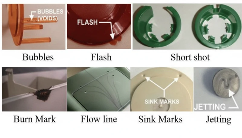
- La sensibilidad a la humedad del PC (requiere <0,02% de humedad) es la causa principal de la mayoría de los defectos superficiales
- Una mayor viscosidad del fundido que el ABS o el PP significa que el PC necesita un control preciso de temperatura y presión
- La tensión interna en piezas transparentes de PC puede causar grietas retardadas días después del moldeo
- La mayoría de los defectos comparten soluciones comunes: secado adecuado, temperatura de cañón optimizada y ventilación suficiente del molde
- La experiencia en fábrica con más de 400 materiales demuestra que solo la disciplina de secado elimina el 60% de los defectos de PC
¿Qué hace que el moldeo por inyección de policarbonato sea tan desafiante?
El policarbonato es uno de los termoplásticos de ingeniería más difíciles de moldear por inyección. Su estructura molecular única —cadenas lineales con anillos de benceno, grupos isopropilideno y enlaces de carbonato— crea tres desafíos principales de procesamiento que lo distinguen de materiales más fáciles como el polipropileno o el ABS.
If you are comparing vendors or planning procurement, our injection molding supplier sourcing guide covers RFQ prep, qualification, and commercial risk checks.
Primero, el PC no tiene un punto de fusión definido. En cambio, se ablanda gradualmente en un amplio rango de temperatura (230–320 °C), lo que significa que la viscosidad de fusión permanece alta1 a lo largo del procesamiento normal. A diferencia de los polímeros semicristalinos que se adelgazan drásticamente por encima de su punto de fusión, el PC se comporta más como un fluido newtoniano: su viscosidad es más sensible a los cambios de temperatura que a la velocidad de cizallamiento. Pequeñas desviaciones de temperatura de solo 10-15 °C pueden llevar la masa fundida de procesable a degradada.
En segundo lugar, el PC es extremadamente sensible a la humedad. Incluso cantidades mínimas de agua (por encima del 0,02% en peso) causan degradación hidrolítica a temperaturas de procesamiento, rompiendo cadenas poliméricas y reduciendo las propiedades mecánicas. Esto significa que un secado previo exhaustivo a 120 °C durante 3-4 horas es obligatorio, no opcional. En nuestra experiencia procesando más de 400 materiales en la fábrica de Shanghái, los defectos relacionados con la humedad representan aproximadamente el 60% de todos los problemas de moldeo de PC que solucionamos.
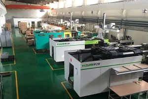
En nuestra fábrica de Shanghái, con más de 20 años de experiencia en moldeo por inyección en más de 400 materiales plásticos, hemos visto todos los patrones de defectos del PC imaginables. El control de humedad y la disciplina en la temperatura del cilindro son las dos variables que separan una producción fluida de PC de un costoso evento de desecho.
En tercer lugar, la alta viscosidad del fundido de PC significa que molde de inyección el diseño debe acomodar presiones de inyección más altas, canales y bebederos más grandes, y ranuras de escape más profundas de lo que se necesitaría para plásticos comunes. Los canales de flujo de tamaño insuficiente generan un calor excesivo por cizallamiento, lo que paradójicamente causa degradación térmica incluso cuando las temperaturas del barril están configuradas correctamente. Comprender estas tres limitaciones —alta viscosidad, sensibilidad a la humedad y sensibilidad al cizallamiento— es la base para prevenir cada defecto cubierto en este artículo.
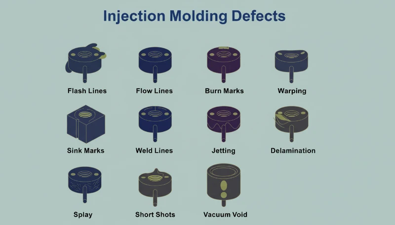
¿Qué causa la decoloración, el amarillamiento y las manchas negras en las piezas de PC?
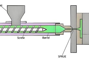
La decoloración es el defecto visual más común en el moldeo por inyección de PC, causado por la degradación térmica del fundido. La causa principal suele ser una temperatura excesiva del barril, un tiempo de residencia demasiado largo o zonas muertas en el sistema de plastificación donde se acumula material degradado y se libera intermitentemente en el flujo del fundido.
La resina de PC pura tiene una excelente estabilidad térmica y puede tolerar temperaturas de hasta 300 °C sin descomposición significativa. El problema surge cuando los procesadores utilizan mezclas de PC modificadas, material reciclado o PC compuesto con retardantes de llama y cargas. Estos aditivos reducen considerablemente la ventana de procesamiento. Por ejemplo, las mezclas PC/ABS suelen requerir temperaturas de barril alrededor de 250 °C, mientras que las mezclas PC/PBT para productos de iluminación necesitan aproximadamente 280 °C; cada combinación tiene su propio límite térmico que, una vez excedido, desencadena un amarillamiento o carbonización irreversible.
Las manchas negras son una variante particularmente frustrante porque pueden aparecer de forma intermitente: a veces dos o tres disparos seguidos, luego desaparecen. Este patrón casi siempre indica material muerto atrapado en algún lugar del sistema de plastificación: huecos del anillo de retención del tornillo, interfaces de la punta del inyector o rayones en la pared del cañón. El material atrapado se carboniza con el tiempo y luego se desprende en trozos. Cuando los productos de descomposición del PC se acumulan más allá de un umbral crítico, también catalizan una mayor descomposición, creando un efecto en cascada, especialmente grave en los grados con retardante de llama.
| Tipo de Material PC | Temperatura de Barril Recomendada | Riesgo de Degradación por Encima de |
|---|---|---|
| PC puro (grado óptico) | 270-300 °C | 320 °C |
| ISO 10993: | 240-260 °C | 280 °C |
| PC con retardante de llama | 230-260 °C | 280 °C |
| Mezcla PC/PBT (iluminación) | 260-280 °C | 300 °C |
| PC reciclado | 240-270 °C | 290 °C (variable) |
Las soluciones son sistemáticas. Primero, verifique los puntos de ajuste de temperatura del barril según el grado del material y reduzca las temperaturas de las zonas de alimentación y compresión en incrementos de 5–10 °C hasta que la decoloración cese. Segundo, asegure un secado completo: 120 °C durante 3–4 horas usando un secador deshumidificador, sin exceder nunca las 10 horas para evitar el envejecimiento del material. Tercero, inspeccione el sistema de plastificación en busca de zonas muertas — retire y limpie la boquilla, el anillo de retención y el tornillo si el fundido de disparo al aire muestra decoloración incluso a temperaturas correctas. Finalmente, purgue el barril con un material térmicamente estable (PS o PE) antes y después de cada corrida de producción, y nunca deje el PC estacionado a temperatura de procesamiento durante paradas prolongadas; baje el barril a 160 °C (Transición vítrea del PC2) o inferior para retenciones térmicas.
“Lowering barrel temperature is always the first step when PC parts show yellowing.”Verdadero
Lowering barrel temperature is the correct first response because excessive heat is the most common cause of PC yellowing. However, if discoloration persists after a 10-15 C reduction, the root cause likely shifts to dead material in the plasticizing system or contaminated raw material.
“Using higher back pressure always improves PC melt quality.”Falso
Excessive back pressure generates additional shear heat in the barrel, which can accelerate thermal degradation of PC. The correct approach is moderate back pressure (0.5-1.5 MPa) combined with adequate drying and proper barrel temperature profiling.
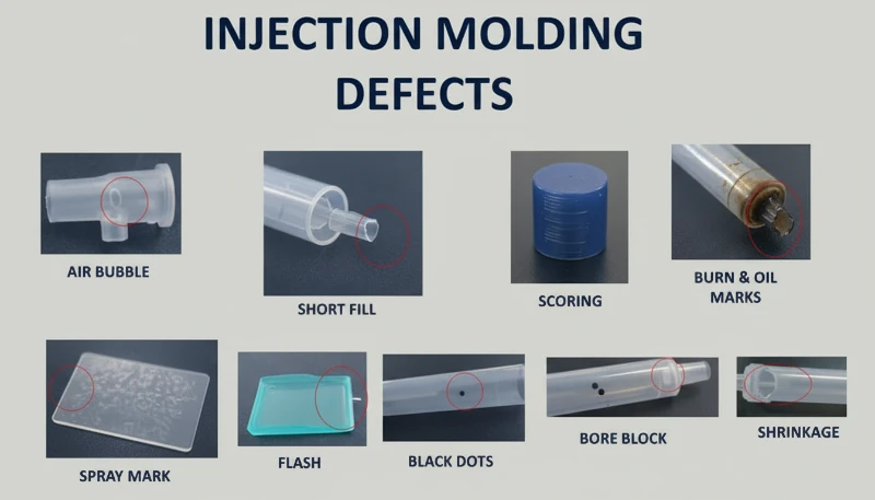
¿Por qué aparecen vetas plateadas y burbujas en los productos de PC?
Silver streaks (also called gas streaks) and bubbles are surface and internal defects caused by gas trapped in the melt during cavity filling. In PC injection molding, the four gas sources are water vapor, entrained air, thermal decomposition gas, and solvent gas—water vapor and decomposition gas account for the vast majority of cases.
Silver streaks form when gas dissolved in the pressurized melt escapes to the product surface as cavity pressure drops after filling. The escaping gas leaves tiny elongated bubbles that sparkle under light, always aligned with material flow direction. Bubbles, on the other hand, are gas pockets trapped in the wall thickness—particularly visible in transparent PC parts. Vacuum bubbles are different: they form not from gas but from volumetric shrinkage when insufficient holding pressure leaves a void in thick sections.
How to Diagnose the Gas Source Behind Silver Streaks
Diagnosing which gas is responsible requires reading the defect pattern. Randomly scattered surface bubbles point to water vapor—the most common culprit in PC because the material is so hygroscopic. Fine, dense bubble clusters concentrated near the gate in a radial or fan-shaped pattern indicate entrained air, typically from excessive screw retraction speed or insufficient back pressure. Discoloration accompanying the silver streaks points to decomposition gas from overheated melt. The diagnostic process matters because each gas source requires a different fix.
For moisture-driven silver streaks, the solution is straightforward: ensure drying at 120 °C for 3–4 hours with a dehumidifying dryer. Verify effectiveness by air-shooting—the extruded melt should be continuous, smooth, and free of white vapor. For air entrainment, reduce screw speed, increase back pressure, and extend melt time during the cooling phase. For decomposition gas, lower barrel temperature section by section starting from the nozzle, and check for excessively long residence times (using oversized equipment for small parts is a common culprit).
Vacuum bubbles require a different approach because they are a shrinkage phenomenon, not a gas issue. Increase holding pressure and extend holding time to pack more material into the thick section. Position the gate at the thickest wall to ensure pressure transmission. Increase mold temperature locally at the void location to slow solidification and allow shrinkage compensation. For transparent products, post-mold slow cooling in hot water can also reduce vacuum bubble formation.
“Post-molding heat treatment at 120 C for 2 hours can significantly reduce internal stress in PC parts.”Verdadero
Heat treatment at approximately 120 C allows PC molecular chain segments to regain mobility and relax frozen elastic deformation. Oriented molecules return toward a random state, reducing both orientation and temperature stress. This is standard practice for optical and stress-critical PC applications.
“Vacuum bubbles in PC parts are caused by trapped air.”Falso
Vacuum bubbles are actually caused by volumetric shrinkage during cooling, not trapped air. When holding pressure is insufficient or the gate freezes too early, the still-molten core shrinks away from the already-solidified skin, creating a void. The fix is increased holding pressure and time, not venting.
¿Qué son las marcas de huellas digitales y las líneas de turbulencia, y cómo se solucionan?
Fingerprint marks and turbulence lines are flow defects caused by PC melt viscosity being too high relative to injection speed and mold temperature. The melt fills the cavity in a stick-slip pattern, leaving wavy lines perpendicular to flow direction (fingerprints) or radial streaks near the gate (turbulence).
Fingerprint marks develop when injection speed and pressure are too low for the melt viscosity. The front of the melt stream contacts the cold mold wall, solidifies, and shrinks. The hot melt behind it pushes the shrunken skin forward, then that layer also cools and shrinks. This alternating advance-freeze cycle creates the characteristic wavy pattern that looks like a human fingerprint. The effect is most visible on large, flat PC surfaces—think display covers or control panels.
Turbulence marks are related but distinct. They appear as irregular flow lines radiating from the gate, caused by the melt hitting the cavity wall at high velocity and skidding across the cold surface before stabilizing into laminar flow. This defect is particularly common when gate design creates a sharp velocity transition—such as a small gate feeding into a large, thick cavity. The key distinction: fingerprints run perpendicular to flow, while turbulence lines run parallel.
Both defects share the same solution set. Increase the nozzle and front barrel temperatures to reduce melt viscosity—this is the single most effective adjustment. Raise mold temperature, especially at the location where marks appear; for appearance-critical PC parts, a mold temperature controller set to 100–120 °C is standard practice. Increase injection speed to shift the filling pattern from stick-slip to continuous flow; multi-stage injection allows you to adjust speed section by section, targeting the problem area without causing flash elsewhere. On the mold side, enlarge gates and runners to reduce flow resistance, and ensure adequate venting and cold-slug wells.
With 47 injection machines ranging from 90T to 1850T, and MOLDFLOW simulation for gate and runner optimization, we typically resolve flow mark issues during the DFM stage—before steel is ever cut. Simulation catches the velocity transitions that cause turbulence marks, allowing gate redesign before tooling.
¿Cómo se forman las manchas de material frío y cómo se pueden prevenir?
Cold material spots are foggy, bright, or worm-shaped marks near the gate caused by partially solidified melt entering the cavity. They form when the melt front loses too much heat at the nozzle tip, runner, or gate before cavity filling begins—or when excessive holding pressure forces already-cooled runner material into the part.
There are two distinct mechanisms. The first is forward cold material: the melt at the nozzle tip and runner entrance cools between shots because the nozzle contacts the cold mold plate. When injection begins, this chilled material enters the cavity first. On thin-walled parts, it spreads into smoky or paste-like cloudy patches. On thick-walled parts, it forms a curved scar resembling an earthworm. The second mechanism is back-pressure cold material: excessive holding time and pressure squeeze already-cooled material from the runner and gate into the part, creating a small circular bright spot near the gate.
Prevention is straightforward but requires attention to detail. Install a cold-slug well at the end of each runner—this traps the forward cold material before it enters the cavity. Increase nozzle temperature to reduce heat loss at the tip. Increase mold temperature to narrow the gap between melt and mold surface temperatures. Reduce injection speed at the start of filling to avoid melt fracture at the gate, then increase speed for the main fill. Optimize gate position, size, and shape to avoid sharp velocity transitions. For holding-pressure cold spots, shorten holding time and reduce holding pressure to the minimum needed for dimensional stability. Also ensure thorough material drying—residual moisture in the cold-slug can worsen the visual defect.
¿Por qué el estrés interno agrieta los productos transparentes de PC?
Internal stress in PC products is frozen-in molecular orientation and uneven cooling stress. It can cause warpage, reduced optical clarity, and delayed stress cracking days or weeks after molding—transparent PC parts are the canary in the coal mine.
Two primary mechanisms create internal stress. Orientation stress comes from polymer chains being stretched during flow and then frozen in place before they can relax back to a random coil configuration. Higher injection pressure, faster injection speed, and longer holding time all increase orientation by applying more shear to the melt. Temperature stress comes from the large temperature differential between the hot melt core and the cold mold wall. Because PC has high specific heat capacity and low thermal conductivity, the surface solidifies long before the interior—creating compressive stress on the outside and tensile stress on the inside.
The practical consequence is that a PC part may look perfect immediately after molding but develop micro-cracks within days, especially when exposed to organic solvents (cleaning agents, adhesives) or elevated temperatures. In our production environment, we have seen transparent PC lenses crack during assembly simply because the operator used an alcohol-based cleaning wipe—the internal stress was already at the failure threshold, and the solvent lowered it just enough to initiate cracking.
Our in-house mold manufacturing facility (100+ mold sets per month) allows us to optimize gate placement, runner geometry, and cooling channel layout specifically for stress-sensitive PC parts. Combined with ISO 9001 and ISO 13485 quality systems, we catch internal stress issues during first-article inspection using polarized light analysis.
“Polarized light analysis can detect internal stress in transparent PC parts before they crack.”Verdadero
Under polarized light, stressed PC exhibits birefringence patterns that reveal frozen molecular orientation and uneven cooling stress. This non-destructive inspection method allows factories to catch stress issues during first-article inspection, long before parts fail in service.
“Post-mold annealing at 120 C reduces internal stress in transparent PC parts.”Falso
Annealing at 120 C does indeed reduce internal stress by allowing molecular chains to relax. However, it is not a substitute for proper molding parameters—it can only reduce stress that was created, not eliminate it entirely. The most effective approach is to minimize stress during molding through correct temperature and pressure settings, then use annealing as a final quality assurance step for critical components.
Reducing internal stress requires a holistic approach. Increase melt temperature to reduce viscosity and orientation during flow. Increase mold temperature to allow slower, more uniform cooling and give oriented molecules time to relax. Reduce injection pressure to the minimum needed for complete filling. Minimize holding time—over-packing is a major contributor to orientation stress. Use variable-speed injection: fast fill to avoid flow defects, then slow speed for holding to reduce molecular alignment. For parts with metal inserts, preheat inserts to approximately 200 °C to reduce the thermal mismatch. Finally, post-mold heat treatment at 120 °C for approximately 2 hours allows chain segments to regain mobility and relax frozen deformation—this is standard practice for optical-grade PC components.
“Reducing injection pressure to the minimum needed for cavity filling helps prevent internal stress in PC parts.”Verdadero
Excessive injection pressure increases molecular orientation and shear stress, which increases internal stress and the risk of warpage and stress cracking. The minimum pressure that achieves complete filling, combined with adequate melt temperature, produces the lowest-stress PC parts.
“Increasing mold temperature above 100 °C always improves the surface finish of PC parts.”Falso
While higher mold temperature can reduce flow marks and improve surface gloss, exceeding 100 °C for extended cycles can cause excessively long cooling times and lead to thermal degradation of the PC resin near the gate. The optimal mold temperature range for PC is typically 80–100 °C, balancing finish quality with cycle efficiency and part stability.
¿Qué parámetros de procesamiento debe monitorear para minimizar los defectos en PC?
There are six parameters that matter most for PC defect prevention: drying, barrel temperature, injection speed, hold pressure, and mold temperature. Getting these right eliminates the vast majority of discoloration, silver streaks, bubbles, flow marks, and internal stress issues.
Drying is non-negotiable. PC requires moisture content below 0.02%3—achieved by dehumidifying dryer at 120 °C for 3–4 hours. Drying beyond 10 hours risks material degradation, especially for flame-retardant grades. Verify drying effectiveness by air-shot inspection before starting production. This single step prevents most silver streaks and surface bubbles.
Barrel temperature must be set as a profile, not a single number. For pure PC, a typical profile runs 250 °C (feed) → 270 °C (compression) → 285 °C (metering) → 290 °C (nozzle). Each modified grade has its own window—PC/ABS at roughly 20 °C lower, PC/PBT at similar or slightly higher temperatures. The key is to start at the lower end of the recommended range and increase only if flow marks or short shots appear. Never set all zones to the same temperature; a proper gradient ensures gradual plasticization without premature melting in the feed zone (which blocks air escape) or under-preheating (which traps air in the melt).
| Parámetro | Recommended Range (Pure PC) | Defects Prevented |
|---|---|---|
| Drying temperature | 120 C, 3-4 h, dehumidified | Silver streaks, surface bubbles |
| Barrel temperature (nozzle) | 280-295 C | Short shots, flow marks |
| Temperatura del molde | 80-120 C | Fingerprint marks, internal stress |
| Velocidad de inyección | Multi-stage: fast fill, slow pack | Turbulence marks, over-packing |
| Presión de mantenimiento | 60-80% of injection pressure | Vacuum bubbles, sink marks |
| Holding time | Until gate freeze (3-8 s) | Shrinkage voids, dimensional drift |
Melt residence time deserves special attention. Using oversized equipment for small PC parts is a common mistake—the large shot-to-barrel-capacity ratio means material sits at processing temperature far too long, accumulating thermal damage. As a rule of thumb, the shot weight should be at least 30–40% of the barrel capacity. If you must run small parts on large machines, use a smaller-diameter screw or accept that frequent purging and color changes are unavoidable. Finally, mold temperature matters more for PC than for most plastics. Running cold molds (below 80 °C) accelerates skin solidification, increases internal stress, and amplifies flow marks. For transparent or appearance-critical parts, 100–120 °C mold temperature with a temperature controller is the industry standard.
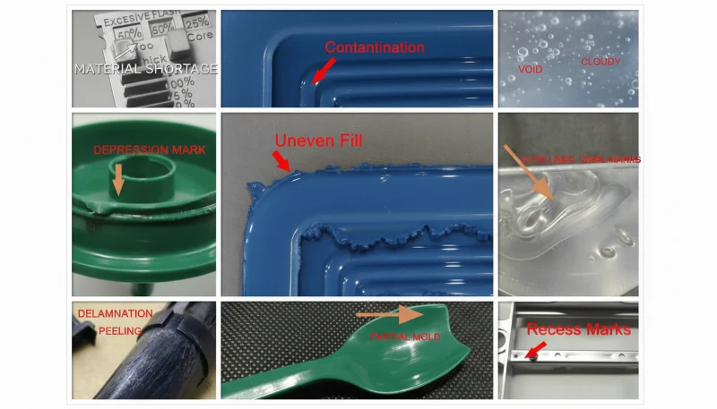
¿Cuáles son las preguntas más comunes sobre los defectos de moldeo por inyección de PC?
Preguntas frecuentes
What is the ideal drying temperature for polycarbonate before injection molding?
Polycarbonate should be dried at 120 C using a dehumidifying dryer for 3 to 4 hours to achieve moisture content below 0.02% before injection molding. This is a non-negotiable requirement for successful PC processing—skipping or short-cutting the drying step is the single most common cause of surface defects. Drying beyond 10 hours risks material degradation, especially for flame-retardant grades which are more thermally sensitive. Always verify effectiveness with an air-shot test before production begins—the extruded melt should be continuous, smooth, and free of white vapor. Using a standard hopper dryer without dehumidification is insufficient for PC.
What causes black spots in polycarbonate injection molded parts?
Black spots in PC injection molded parts are typically caused by carbonized material trapped in dead zones of the plasticizing system—such as screw check ring gaps, nozzle tip interfaces, or barrel wall scoring. The trapped material degrades over time and intermittently breaks loose into the melt stream, producing dark spots that appear randomly across several shots then disappear. Regular disassembly and cleaning of the plasticizing system, combined with proper barrel purging procedures using PS or PE before and after each production run, prevents this issue effectively. Never leave PC material sitting at processing temperature during extended machine stops.
What is the recommended injection molding temperature for polycarbonate?
For pure polycarbonate, the recommended barrel temperature profile is 250 C (feed zone) to 285-295 C (nozzle), with mold temperature at 80-120 C. The key is to use a temperature gradient across zones rather than a single setpoint, ensuring gradual plasticization without premature melting in the feed zone. Modified grades have different windows: PC/ABS blends run approximately 20 C lower, while PC/PBT blends may require similar or slightly higher temperatures. Always start at the lower end of the recommended range and increase only if flow defects appear.
How do you prevent internal stress in transparent PC products?
Preventing internal stress in transparent PC parts requires a multi-pronged approach. Use higher melt temperature to reduce viscosity and molecular orientation during flow. Increase mold temperature to 100-120 C for slower and more uniform cooling that gives oriented molecules time to relax. Minimize injection and holding pressure to the minimum needed for complete filling. Use variable-speed injection with fast fill followed by slow pack. Post-mold heat treatment at 120 C for approximately 2 hours is standard practice for optical-grade components to relax frozen molecular orientation.
Why do silver streaks appear on PC injection molded parts?
Silver streaks on PC parts are caused by gas escaping to the product surface during or after cavity filling, leaving tiny elongated bubbles that sparkle under light. The most common gas source is water vapor from inadequately dried material—this accounts for the majority of cases. Thermal decomposition gas from excessive barrel temperature is the second most common cause. Fine dense silver streaks concentrated near the gate in a radial pattern indicate entrained air from excessive screw speed or insufficient back pressure. Proper drying at 120 C for 3-4 hours eliminates most moisture-driven cases.
Can polycarbonate injection molding defects be fixed by adjusting only the machine parameters?
Many PC defects—particularly silver streaks, discoloration, and flow marks—can be resolved through machine parameter adjustments alone, primarily drying conditions, barrel temperature profiling, and injection speed optimization. However, recurring defects like persistent cold material spots or turbulence marks often require mold modifications such as enlarged gates, additional venting channels, or cold-slug wells. Internal stress reduction may also require design changes to wall thickness uniformity and insert preheating. The most effective approach combines parameter optimization with proper mold design from the start.
What is the difference between bubbles and vacuum bubbles in PC parts?
Bubbles in PC parts are gas-filled voids caused by water vapor, entrained air, or thermal decomposition gas trapped during cavity filling. They are present immediately upon mold opening and do not grow over time. Vacuum bubbles are fundamentally different—they are shrinkage-induced voids that form during cooling when holding pressure is insufficient to compensate for volumetric shrinkage in thick sections. Vacuum bubbles may appear or enlarge after demolding as the interior continues to cool and contract. The diagnostic difference determines whether you address gas content through drying and temperature, or packing through holding pressure.
¿Cómo puede obtener soporte experto para su proyecto de moldeo por inyección de PC?
ZetarMold is the manufacturing partner for polycarbonate injection molding projects that demand zero defects. Our engineering team brings 20+ years of experience processing PC and 400+ materials to every project, from material drying and temperature profiling to gate design and stress relief. Our in-house tooling facility, MOLDFLOW simulation capability, and ISO-certified quality systems mean your PC parts are engineered for quality from the DFM stage onward.
Need a quote for your polycarbonate injection molding project? Get competitive pricing, DFM feedback, and production timeline from our engineering team. Request a Free Quote today, or explore our Injection Molding Complete Guide for a comprehensive overview of the process.
-
la viscosidad de fusión permanece alta: melt viscosity remains high refers to pC melt viscosity is more sensitive to temperature changes than to shear rate, behaving similarly to a Newtonian fluid during processing. ↩
-
Transición vítrea del PC: PC glass transition refers to polycarbonate has a glass transition temperature (Tg) of approximately 147-150 C, which determines minimum thermal hold temperature. ↩
-
moisture content below 0.02%: moisture content below 0.02% refers to pC requires moisture content below 0.02% (200 ppm) before processing to prevent hydrolytic degradation at molding temperatures. ↩


 EN
EN  ES
ES  FR
FR  DE
DE  PT
PT  AR
AR  RU
RU  JA
JA  KO
KO  IT
IT  NL
NL  TR
TR  PL
PL 