 Zum Inhalt springen

Berechnung der Projektionsfläche1 ist einer der ersten und wichtigsten Schritte in jedem Spritzgießen2 Projekt. Machen Sie es falsch, und Sie riskieren Blitzlicht3 Fehler, Maschinenschäden oder die Unfähigkeit, die Form zu füllen. Machen Sie es richtig, und Sie können sicher die richtige Presse auswählen, die Schließkraft abschätzen und von Anfang an qualitativ hochwertige Teile produzieren.
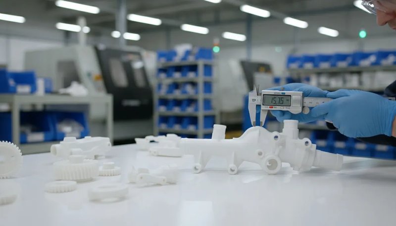
In unserem Werk in Shanghai betreiben wir 47 Spritzgießmaschinen mit einer Leistung von 90T bis 1850T. Jedes Projekt beginnt mit derselben Frage: Wie groß ist die projizierte Fläche, und verfügt unsere Ausrüstung über genügend Schließkraft? Diese Anleitung führt Sie durch den Berechnungsprozess mit echten Formeln, ausgearbeiteten Beispielen und praktischen Tipps aus zwei Jahrzehnten Produktionserfahrung.
- Die Projektionsfläche ist die 2D-Silhouette Ihres Bauteils entlang der Schließrichtung
- Schließkraft = Projektionsfläche × Kavitätendruck × Sicherheitsfaktor
- Schließen Sie immer Läufer- und Angussflächen in Ihre Berechnung ein
- Komplexe Formen können in einfachere geometrische Formen zerlegt werden
- Eine Sicherheitsmarge von 10-20% verhindert Gratbildung und unvollständige Füllung
Was ist die Projektionsfläche im Spritzguss?
Die Projektionsfläche im Spritzguss ist der zweidimensionale Schatten oder die Silhouette Ihres Bauteils, wenn es aus der Richtung betrachtet wird, in der die Form schließt. Stellen Sie sich vor, Sie halten eine Taschenlampe direkt über einen Gegenstand – der Schatten, den er auf den Tisch wirft, ist seine Projektionsfläche. Diese Messung, typischerweise in Quadratzentimetern (cm²) oder Quadratzoll (in) angegeben, bestimmt direkt, wie viel Schließkraft Ihre Maschine benötigt, um die Form während des Einspritzens geschlossen zu halten.
Für einen breiteren Überblick deckt unser Spritzgießen Komplettleitfaden behandelt Prozessgrundlagen, Materialverhalten und Produktionsentscheidungen.
If you are comparing vendors or planning procurement, our injection molding supplier sourcing guide covers RFQ prep, qualification, and commercial risk checks.
Warum ist das so wichtig? Wenn geschmolzener Kunststoff unter hohem Druck in den Formhohlraum eintritt, erzeugt er eine nach außen gerichtete Kraft, die proportional zur projizierten Fläche ist. Wenn die Schließkraft der Maschine geringer ist als diese nach außen gerichtete Kraft, öffnet sich die Form leicht an der Trennlinie, was zu Gratbildung führt — dünne, unerwünschte Kunststoffgrate entlang der Kanten Ihres Teils. In Produktionsumgebungen bedeutet Grat Nacharbeit, Ausschuss oder abgelehnte Teile.
In unserem Werk in Shanghai betreiben wir 47 Spritzgießmaschinen von 90T bis 1850T. Jedes neue Projekt beginnt mit der Berechnung der projizierten Fläche, um sicherzustellen, dass wir eine Presse mit ausreichender Schließkraft auswählen — diese einzelne Berechnung verhindert kostspieliges Trial-and-Error auf der Produktionsfläche.
Wie berechnet man die Projektionsfläche Schritt für Schritt?
Die Projektionsfläche wird berechnet, indem das Bauteil in einfache geometrische Formen zerlegt, jede Silhouette vermessen und die Ergebnisse summiert werden. Hier ist unsere Schritt-für-Schritt-Methode.
Schritt 1: Bestimmung der Einspannrichtung
Bevor Sie etwas messen, identifizieren Sie die Richtung, in der die Form öffnet und schließt. Dies ist üblicherweise senkrecht zur Trennlinie. Die Projektionsfläche wird entlang dieser Achse gemessen. Für die meisten Standardteile ist dies die Richtung, in der sich die Pressenplatten bewegen.
Schritt 2: Zerlegen Sie das Bauteil in einfache geometrische Formen
Betrachten Sie das Teil von der Einspannrichtung aus. Unterteilen Sie seinen Umriss in Grundformen — Rechtecke, Kreise, Dreiecke und Trapeze. Jede Form hat eine bekannte Flächenformel:
Hier sind die grundlegenden Formeln, die Sie benötigen: Rechteck = Länge x Breite (z.B. 50 mm x 30 mm = 1.500 mm²); Kreis = pi x Radius im Quadrat (z.B. pi x 20² = 1.257 mm²); Dreieck = 0,5 x Grundseite x Höhe (z.B. 0,5 x 40 x 25 = 500 mm²); Trapez = 0,5 x (a + b) x h (z.B. 0,5 x (30 + 50) x 20 = 800 mm²).
Schritt 3: Berechnen Sie jede Form und summieren Sie sie
Wenden Sie die entsprechende Formel auf jede Teilform an und addieren Sie dann alle Flächen. Für ein Teil, das wie ein Rechteck mit einem halbkreisförmigen Anhang aussieht, würden Sie die rechteckige Fläche, die halbkreisförmige Fläche berechnen und diese addieren.
Schritt 4: Läufer- und Angussflächen hinzufügen
Vergessen Sie nicht das Anguss-System. Das geschmolzene Plastik fließt durch Angüsse und Einlauftore, bevor es in die Kavität gelangt. Diese Kanäle erzeugen ebenfalls eine nach außen gerichtete Kraft auf die Form. Schließen Sie die Projektionsfläche des Angusses in Ihre Gesamtfläche ein. Bei Mehrfachkavitätenformen multiplizieren Sie die Einzelkavitätenfläche mit der Anzahl der Kavitäten und addieren dann die gesamte Angussfläche.
Schritt 5: Anwendung des Zugwinkelkorrektur (falls erforderlich)
Bei Teilen mit signifikanten Schrägen kann die projizierte Fläche von der Messung der ebenen Fläche abweichen. Die meisten Schrägen (1-3 Grad) haben einen vernachlässigbaren Einfluss, aber für Tiefziehteile mit 5+ Grad Schräge sollte die Silhouette unter Berücksichtigung der schrägen Wände neu berechnet werden. In der Praxis überschreitet diese Korrektur selten 2-3% der Gesamtfläche.
Wie lautet die Formel für die Schließkraft aus der projizierten Fläche?
Sobald Sie die projizierte Fläche haben, ist die Schließkraftformel der Schlüssel zur Auswahl der richtigen Maschine. Die grundlegende Gleichung lautet:
Schließkraft (kgf) = Projektionsfläche (cm²) × Kavitätendruck (kgf/cm²)
Umrechnung in Tonnen (wobei 1 Tonne = 1.000 kgf):
Tonnage = [Projizierte Fläche (cm²) × Kavitätendruck (kgf/cm²)] ÷ 1.000
Der Kavitätendruck hängt vom zu verarbeitenden Material ab. Hier sind typische Kavitätendruckwerte für gängige Materialien:
| Material | Kavitätendruck (kgf/cm²) | Kavitätendruck (Tonnen/Quadratzoll) |
|---|---|---|
| PS (Polystyrol) | 150–250 | 1,0–1,7 |
| PE (Polyethylen) | 200–300 | 1,4–2,1 |
| PP (Polypropylen) | 200–350 | 1,4–2,5 |
| ABS | 300–500 | 2,1–3,5 |
| PA (Nylon) | 350–600 | 2,5–4,2 |
| PC (Polycarbonat) | 400–700 | 2,8–4,9 |
| POM (Acetal) | 350–550 | 2,5–3,9 |
| PBT | 350–550 | 2,5–3,9 |
Wenden Sie stets einen Sicherheitsfaktor von 1,1 bis 1,2 auf die berechnete Tonnage an. Dies berücksichtigt Viskositätsänderungen, Formtemperaturschwankungen und Prozessanpassungen. In unserer Praxis verwenden wir typischerweise einen Sicherheitszuschlag von 15 %.
Wie berechnet man die projizierte Fläche für gängige Teilformen?
Grundformen verwenden Standardgeometrie: Länge mal Breite für Rechtecke, Pi mal Radius quadriert für Kreise und Zerlegung für komplexe Teile.
Beispiel 1: Flaches rechteckiges Teil
Eine flache Deckplatte misst 120 mm × 80 mm. Die Form schließt an der dünnen Dimension (Dickenrichtung), daher ist die projizierte Fläche einfach die Fläche der Oberfläche:
Projizierte Fläche = 120 mm × 80 mm = 9.600 mm² = 96 cm²
Bei Verarbeitung in ABS (Kavitätendruck ≈ 400 kgf/cm²) wäre die erforderliche Tonnage: Tonnage = (96 cm² × 400 kgf/cm²) ÷ 1.000 = 38,4 Tonnen. Mit einem Sicherheitsfaktor von 15 %: 38,4 × 1,15 = 44,2 Tonnen. Eine 50-Tonnen-Presse würde dies problemlos bewältigen.
Beispiel 2: Zylindrisches Teil
Eine zylindrische Buchse mit einem Außendurchmesser von 60 mm. Die projizierte Fläche ist ein Kreis:
Projizierte Fläche = π × r² = 3,14159 × 30² = 2.827 mm² = 28,3 cm²
Hinweis: Wenn der Zylinder hohl ist, NICHT den inneren Durchmesser von der projizierten Fläche subtrahieren. Die Schließkraft wirkt auf die gesamte kreisförmige Silhouette, nicht nur auf den Wandquerschnitt.
Beispiel 3: L-förmige Halterung
Ein L-förmiger Winkel kann in zwei Rechtecke unterteilt werden: Rechteck A (60 × 40 mm) und Rechteck B (40 × 30 mm). Wenn sich die beiden Rechtecke um 40 × 30 mm überlappen, beträgt die Gesamtfläche:
Projizierte Fläche = (60 × 40) + (40 × 30) – (40 × 30) = 2.400 mm² = 24 cm²
Das Grundprinzip: Zerlege jede komplexe Form in einfache Formen, berechne jede Fläche und addiere sie, während überlappende Bereiche subtrahiert werden.
Welche Faktoren beeinflussen die Berechnung der projizierten Fläche?
Die Genauigkeit der projizierten Fläche wird durch vier Faktoren bestimmt: Teilgeometrie, Kavitätenanzahl, Verteilerdesign und Formmerkmale wie Schieber und Lifter.
Komplexität der Teilgeometrie
Komplexe Teile mit Rippen, Ansätzen, Hinterschneidungen und variierenden Wandstärken erzeugen Projektionen, die keine einfachen Rechtecke oder Kreise sind. Verwenden Sie CAD-Software, um die genaue projizierte Fläche aus Ihrem 3D-Modell zu extrahieren. Die meisten modernen CAD-Pakete (SolidWorks, Creo, NX) können die projizierte Fläche automatisch entlang jeder Achse berechnen.
Anzahl der Hohlräume
Bei Mehrfachkavitätenformen ist die gesamte projizierte Fläche die Einzelkavitätenfläche multipliziert mit der Anzahl der Kavitäten plus die Angussfläche. Eine Vierfachkavitätenform mit einer Einzelkavitätenfläche von 50 cm² und einer Angussfläche von 20 cm² hat eine Gesamtprojektionsfläche von (4 × 50) + 20 = 220 cm².
Läufersystem-Design
Kaltangüsse erhöhen die Fläche erheblich. Ein vollrunder Anguss mit 8 mm Durchmesser und 150 mm Länge über die Form hinweg addiert 12 cm² zur projizierten Fläche. Heißkanalsysteme reduzieren, obwohl teurer, die projizierte Fläche durch den Wegfall des Kaltangusskanals – was manchmal den Einsatz einer kleineren, kostengünstigeren Presse ermöglicht.
Werkzeugkonstruktionsmerkmale
Schieber, Auswerfer und Kernzüge können die effektive projizierte Fläche verändern. Seitenschieber insbesondere können zusätzliche projizierte Fläche in Winkeln einführen, die aus der Draufsicht nicht sofort ersichtlich ist. Überprüfen Sie immer das vollständige Formgestaltung mit Ihrem Werkzeugbauingenieur.

„Die Verteilerfläche muss in die Berechnung der projizierten Fläche für Mehrkavitätenformen einbezogen werden.“Wahr
Das Angusssystem trägt 10–25 % zur gesamten projizierten Fläche bei. Wird es vernachlässigt, führt dies zu einer Unterschätzung der Tonnage, was zu Gratbildung und Formtrennung während des Spritzvorgangs führt.
„Bei einem hohlzylindrischen Teil sollten Sie die innere Bohrung von der projizierten Fläche abziehen.“Falsch
Die Schließkraft wirkt auf die gesamte kreisförmige Silhouette des Teils, einschließlich des hohlen Inneren. Der Kavitätendruck wirkt nach außen gegen die gesamte projizierte Fläche, nicht nur gegen den Wandquerschnitt.
Wie beeinflusst die projizierte Fläche die Maschinenauswahl?
Der erforderliche Maschinendruck ist direkt proportional zur projizierten Fläche. Unterdimensionierung führt zu Gratbildung, Kurzschüssen und Maßabweichungen in der Produktion.
Mit unserer Maschinenflotte von 90T bis 1850T können wir nahezu jedes Projekt der richtigen Presse zuordnen. So lässt sich die Berechnung auf die Maschinenauswahl übertragen:
Bei der Auswahl einer Maschine ist auch die Plattenengröße zu berücksichtigen. Der Werkzeug muss in die Maschinenplatte passen, und die projizierte Fläche sollte etwa zwei Drittel der gesamten Plattenfläche nicht überschreiten. Wenn Ihre projizierte Fläche mehr als 70% der Platte bedeckt, wird die Schließkraftverteilung ungleichmäßig, was das Risiko von Gratbildung in den Ecken erhöht. Ein weiterer Faktor ist der Abstand der Zuganker: Ein zu breiter Werkzeug für die Zuganker kann unabhängig von der Tonnage nicht montiert werden. Vergleichen Sie immer Ihre Werkzeugabmessungen und die projizierte Fläche mit dem Maschinenspezifikationsblatt, bevor Sie sich für einen Prototyp oder eine Serienfertigung entscheiden.
| Gesamtprojizierte Fläche (cm²) | Material | Erforderlicher Druck (Tonnen) | Empfohlener Maschinenbereich |
|---|---|---|---|
| < 100 | PP/PE | 15–35 | 90T |
| 100–300 | ABS/PA | 40–120 | 120T–200T |
| 300–800 | PC/POM | 120–350 | 200T–500T |
| 800–2.000 | PA/PC | 350–800 | 500T–1000T |
| > 2.000 | Verschiedene | 800+ | 1000T–1850T |
Unsere interne Formenbau-Einrichtung unterstützt mehr als 100 Formensätze pro Monat, was bedeutet, dass wir projizierte Flächenberechnungen während der DFM-Phase schnell validieren und Formkonstruktionen anpassen können, bevor der Stahl überhaupt bearbeitet wird – das spart Zeit und verhindert kostspielige Überraschungen während der Produktionsversuche.

Was sind die häufigsten Fehler bei der Berechnung der Projektionsfläche?
Die häufigsten Fehler sind das Auslassen der Angussfläche, das Überspringen von Sicherheitsfaktoren, das Messen der falschen Achse und das Ignorieren von Hinterschneidungen. Wir haben all diese Fehler in der Produktion korrigiert.
Angussfläche vergessen
Dies ist der häufigste Fehler. Ingenieure berechnen die Bauteilfläche perfekt, vergessen aber, dass das Angusssystem ebenfalls zum Schließkraftbedarf beiträgt. Bei Mehrfachwerkzeugen kann die Angussfläche 10-25% zum Gesamtwert hinzufügen. Beziehen Sie sie immer ein.
Vernachlässigung des Sicherheitsfaktors
Eine Maschine bei genau 100% ihrer Nenntonnage zu betreiben, lässt keinen Spielraum für Prozessschwankungen. Materialviskositätsänderungen, Formtemperaturschwankungen und Einspritzgeschwindigkeitsanpassungen beeinflussen alle die tatsächliche Kraft. Ein Sicherheitsfaktor von 10-20% ist nicht optional – er ist essenziell.
Falsche Dimension messen
Für asymmetrische Teile ändert sich die projizierte Fläche je nach Richtung, in der sich die Form öffnet. Ein Teil könnte eine kleine projizierte Fläche in einer Orientierung und eine große in einer anderen haben. Messen Sie immer entlang der tatsächlichen Schließrichtung der vorgesehenen Formkonstruktion.
Hinterschritte nicht berücksichtigen
Teile mit Hinterschneidungen oder seitlichen Merkmalen können eine zusätzliche projizierte Fläche haben, die aus der primären Schließrichtung nicht sichtbar ist. Seitenschieber übertragen Kraft in Winkeln und erzeugen Vektorkomponenten, die zum gesamten Schließkraftbedarf beitragen.
Wie verwendet man CAD-Software zur Berechnung der Projektionsfläche?
Der schnellste Weg zur Ermittlung der projizierten Fläche ist die Verwendung von CAD-Software. SolidWorks, Creo und NX berechnen die Silhouette entlang jeder Achse in Sekunden.
„Ein Sicherheitsfaktor von 10–20 % über der berechneten Spannkraft ist in der Spritzgießbranche üblich.“Wahr
Diese Marge berücksichtigt Materialviskositätsänderungen, Formtemperaturschwankungen und normalen Maschinenverschleiß. Betrieb bei 100% der Nennkapazität lässt keinen Spielraum für Prozessanpassungen.
„Die Verwendung einer Maschine mit der doppelten erforderlichen Tonnage erzeugt immer qualitativ hochwertigere Teile.“Falsch
Überdimensionierte Pressen verschwenden Energie, erhöhen die Zykluszeit aufgrund größerer Aufspannplatten und können eine übermäßige Kompression auf die Form verursachen, was zu vorzeitigem Verschleiß an Trennlinien und Auswerferstiften führt.
In SolidWorks verwenden Sie das Messwerkzeug mit der Option 'Projizierte Fläche' und wählen die Ebene senkrecht zur Klemmrichtung aus. In Creo (Pro/E) verwenden Sie Analyse → Messen → Fläche mit aktivierter Projektion. In Siemens NX bietet der Befehl 'Flächen messen' eine Option für die Projektionsrichtung.
Diese Tools liefern Ihnen die genaue projizierte Fläche in Sekunden, einschließlich komplexer organischer Formen, Verrundungen und Schrägen. Für kritische Anwendungen überprüfen wir CAD-Ergebnisse immer mit manuellen Berechnungen – das dauert 30 Sekunden länger und fängt potenzielle Fehler ab.
Welche Beziehung besteht zwischen projizierter Fläche und Bauteilqualität?
Die projizierte Fläche beeinflusst nicht nur die Maschinenauswahl – sie wirkt sich direkt auf die Teilequalität und die Maßtoleranz aus. Eine Unterschätzung der projizierten Fläche (und damit der erforderlichen Tonnage) führt zu mehreren Qualitätsproblemen.
Gratbildung ist das offensichtlichste Symptom. Wenn die Schließkraft unzureichend ist, öffnet sich die Form an der Trennlinie um auch nur einige Hundertstelmillimeter, und geschmolzener Kunststoff entweicht. Neben Gratbildung kann unzureichende Tonnage zu Maßinstabilität führen – die Bauteildicke variiert, weil sich die Form unter dem Einspritzdruck verbiegt. In schweren Fällen führt dies zu Bauteilgewichtsabweichungen und Einfallstellen.
Umgekehrt führt eine grobe Überschätzung der projizierten Fläche und der Einsatz einer überdimensionierten Presse zu Energieverschwendung, erhöht die Zykluszeit (größere Aufspannplatten brauchen länger zum Öffnen und Schließen) und kann eine übermäßige Kompression auf die Form verursachen, was zu vorzeitigem Verschleiß an Trennlinien, Auswerferstiften und Maßabweichungen führt.
Der Sweet Spot liegt bei 80-90 % der Nennspannkraft der Maschine. Dies gewährleistet ausreichende Schließkraft mit etwas Spielraum für Prozessanpassungen, während die Ineffizienzen einer überdimensionierten Presse vermieden werden.
Wie optimiert man die Bauteilkonstruktion, um die projizierte Fläche zu reduzieren?
Manchmal ist die projizierte Fläche für die verfügbare Maschine zu groß. Bevor Sie in eine größere Presse investieren, sollten Sie diese Konstruktionsoptimierungen in Betracht ziehen, um die projizierte Fläche zu verringern.
Überarbeiten Sie die Trennebene. Eine Verschiebung der Trennebene kann ändern, welche Merkmale entlang der Schließachse projiziert werden. Ein Teil, das im Werkzeug in einem anderen Winkel ausgerichtet ist, kann eine deutlich kleinere projizierte Fläche aufweisen.
Reduzieren Sie die Anzahl der Kavitäten. Wenn ein Vierkavitäten-Werkzeug zu viel Spannkraft erfordert, halbiert ein Zweikavitäten-Werkzeug die teilebezogene projizierte Fläche. Sie opfern Durchsatz, aber es kann wirtschaftlicher sein als der Kauf einer größeren Maschine.
Wechseln Sie zu einem Heißkanalsystem. Das Entfernen von Kaltläufern beseitigt deren Beitrag zur projizierten Fläche. Bei knappen Berechnungen kann dies allein den Unterschied ausmachen, ob eine 500-Tonnen-Presse ausreicht oder eine 650-Tonnen-Maschine benötigt wird.
Erwägen Sie Einsetzen oder Umspritzen. Diese Techniken können die Größe jedes einzelnen Spritzvorgangs reduzieren, während sie weiterhin ein komplexes Endteil durch mehrere Operationen auf kleineren Maschinen produzieren. Das Einsetzen ermöglicht es Ihnen außerdem, Metall- und Kunststoffkomponenten in einem Arbeitsgang zu kombinieren, sodass nachträgliche Montageschritte entfallen und die Gesamtproduktionskosten sinken, während die projizierte Fläche für Standard-Spannkraftmaschinen handhabbar bleibt.
Eine weitere effektive Strategie ist die Änderung der Angusslage. Durch Verlegung des Angusses näher zur Partiemitte kann die Fließlänge reduziert werden, was wiederum den benötigten Einspritzdruck und die Schließkraft verringert. Symmetrische Angussplatzierung verteilt den Druck gleichmäßiger über die Kavität, minimiert so weiter das Risiko von Gratbildung und sorgt für eine konsistente Bauteilqualität über die gesamte projizierte Fläche.
Mit über 20 Jahren Erfahrung über mehr als 400 Kunststoffmaterialien hinweg unterstützt unser Engineering-Team routinemäßig Kunden bei der Optimierung von Bauteildesigns und Werkzeuglayouts, um die projizierte Fläche zu minimieren – oft wird die benötigte Maschinenspannkraft um 20–30 % reduziert, ohne die Bauteilqualität zu beeinträchtigen.
Was sind die häufigsten Fragen zur projizierten Fläche beim Spritzgießen?
Häufig gestellte Fragen
Was ist die projizierte Fläche im Spritzgießen?
Die projizierte Fläche im Spritzgießen ist die zweidimensionale Silhouette eines Teils, betrachtet entlang der Schließrichtung. Sie stellt die maximale Querschnittsfläche dar, gegen die das geschmolzene Kunststoff während des Einspritzvorgangs drückt, und bestimmt direkt die benötigte Schließkraft, um das Werkzeug während des Füll- und Nachdruckvorgangs geschlossen zu halten. Ingenieure berechnen sie, indem sie den Umriss des Teils aus der Schließrichtung vermessen und das Ergebnis in Quadratzentimeter oder Quadratzoll umrechnen. Diese Messung ist entscheidend für die richtige Maschinenauswahl.
Wie berechnet man die Klemmkraft aus der projizierten Fläche?
Die Schließkraft entspricht der gesamten projizierten Fläche – einschließlich sowohl des Bauteilhohlraums als auch des Angusssystems – multipliziert mit dem Hohlraumdruck des zu verarbeitenden Materials, dividiert durch 1.000 zur Umrechnung von Kilogramm-Kraft in metrische Tonnen. Beispielsweise benötigt ein Teil mit 150 cm² projizierter Fläche, das in ABS mit 400 kgf/cm² gespritzt wird, (150 × 400) ÷ 1.000 = 60 Tonnen Schließkraft. Ingenieure fügen immer einen Sicherheitsfaktor von 10 bis 20 Prozent hinzu, um Viskositätsänderungen, Temperaturschwankungen und normale Prozessschwankungen während der Produktionsläufe zu berücksichtigen.
Beeinflusst die Angussfläche die Berechnung der projizierten Fläche?
Ja, das Angusssystem beeinflusst absolut die gesamte projizierte Fläche und muss in jede Tonnageberechnung einbezogen werden. Die Schließkraft muss dem Einspritzdruck standhalten, der sowohl auf den Hohlraum als auch auf die Angusskanäle wirkt. Bei Mehrfachwerkzeugen kann die Angussfläche 10 bis 25 Prozent zur gesamten projizierten Fläche hinzufügen. Für kritische Produktionsanwendungen müssen Ingenieure das vollständige Angusslayout in die Berechnung einbeziehen, um eine Unterschätzung der Tonnage zu vermeiden, die zu Gratbildung und Maßabweichungen auf der Produktionsfläche führen würde.
Was passiert, wenn die Maschinentonnage für die projizierte Fläche zu gering ist?
Wenn die Maschinenspannkraft für die projizierte Fläche nicht ausreicht, öffnet sich das Werkzeug während der Hochdruckeinspritzphase leicht an der Trennebene. Diese Öffnung verursacht Grat – dünne Kunststoffhäute, die an den Kanten des Teils entweichen und nachträgliches Entgraten erfordern oder zur Ausschussbildung führen. In schwereren Fällen führt unzureichende Schließkraft zu Maßabweichungen über die Trennebene, zu Kurzschüssen, bei denen das Werkzeug nicht vollständig gefüllt wird, und zu ungleichmäßigem Teilegewicht von Schuss zu Schuss. Die Wahl einer Maschine mit mindestens 10 bis 20 Prozent mehr Spannkraft als berechnet verhindert diese kostspieligen Produktionsprobleme.
Wie berechnet man die projizierte Fläche für komplexe Formen?
Bei komplexen Formen zerlegen Sie die Geometrie in einfache Formen – Rechtecke, Kreise und Dreiecke – und berechnen dann jede Fläche separat mit Standard-Geometrieformeln. Summieren Sie alle Teilflächen und subtrahieren Sie überlappende Bereiche, um die Gesamtfläche zu erhalten. Für organische oder freiformartige Oberflächen verwenden Sie CAD-Software mit dem Messwerkzeug für projizierte Fläche, welches die genaue Silhouettenfläche entlang einer beliebigen Richtung in Sekunden berechnet. Die meisten modernen CAD-Pakete wie SolidWorks, Creo und NX enthalten diese Funktionalität als integrierte Messfunktion für Spritzgießwerkzeug-Designer.
Was ist der Sicherheitsfaktor für die Spritzgieß-Spannkraft?
Der Standard-Sicherheitsfaktor für die Spritzgieß-Tonnage liegt bei 1,1 bis 1,2, was bedeutet, dass die ausgewählte Maschine 10 bis 20 Prozent über der berechneten Schließkraft liegen sollte. Diese Marge berücksichtigt Viskositätschwankungen des Materials zwischen den Chargen, Formtemperaturänderungen während längerer Produktionsläufe, Einspritzgeschwindigkeitsanpassungen während der Prozessoptimierung und den normalen Verschleiß des Hydrauliksystems im Laufe der Zeit. Der Betrieb einer Maschine genau an ihrer Nennkapazität lässt keinen Spielraum für die Prozessanpassungen, die routinemäßig erforderlich sind, um eine konsistente Bauteilqualität während eines Produktionslaufs aufrechtzuerhalten.
Kann die Berechnung der projizierten Fläche die Herstellungskosten senken?
Die genaue Berechnung der projizierten Fläche senkt die Herstellungskosten hauptsächlich, indem sie eine Überdimensionierung der Maschinengröße verhindert, was sich direkt auf die Stundensätze und den Energieverbrauch auswirkt. Das Laufen eines Teils auf einer 200-Tonnen-Presse anstelle einer unnötigen 350-Tonnen-Maschine spart Energie, reduziert den für den Auftrag berechneten Maschinenstundensatz und verkürzt oft die Zykluszeiten, da kleinere Platten sich schneller öffnen und schließen. Die Optimierung der Teileausrichtung, des Angussdesigns oder des Kavitätenlayouts zur Minimierung der projizierten Fläche ist eine der kosteneffektivsten Strategien, die während der Formenbauphase zur Verfügung stehen.
Ist die projizierte Fläche gleich der Bauteiloberfläche?
Nein, projizierte Fläche und Oberfläche sind grundlegend verschiedene Messungen. Oberfläche ist die Gesamtfläche aller externen Oberflächen eines dreidimensionalen Bauteils, einschließlich jeder Kontur, Rippe und Boss. Projizierte Fläche ist nur die zweidimensionale Silhouette, die aus einer bestimmten Richtung betrachtet wird – der Schließrichtung. Eine Kugel mit einer Oberfläche von 1.256 cm² hat eine projizierte Fläche von nur etwa 400 cm², wenn sie aus jedem Blickwinkel betrachtet wird. Die Schließkraft, die für das Spritzgießen benötigt wird, hängt von der projizierten Fläche ab, nicht von der Gesamtoberfläche des geformten Bauteils.
Wie können Sie die Berechnung der projizierten Fläche beherrschen, um bessere Spritzgießergebnisse zu erzielen?
Die Berechnung der projizierten Fläche ist die Grundlage für die richtige Maschinenauswahl, die Formgestaltung und die Produktionsqualität. Die Formel ist einfach: Messen Sie die Silhouettenfläche in Richtung der Schließkraft, addieren Sie die Angussfläche, multiplizieren Sie mit dem Formdruck und verwenden Sie einen Sicherheitsfaktor von 1,1–1,2.
Ob Sie einen einfachen Halter oder ein komplexes Mehrfachformteil entwerfen Spritzgussform, eine korrekte Berechnung spart Zeit, verhindert Defekte und hilft, Ihre Produktionskosten unter Kontrolle zu halten.
Bei ZetarMold bringt unser Engineering-Team über 20 Jahre praktische Erfahrung in jedes Projekt. Von der DFM-Prüfung bis zur Produktionsoptimierung helfen wir Ihnen, die projizierte Fläche direkt richtig zu bestimmen – damit Ihre Bauteile vom ersten Schuss perfekt sind.
Brauchen Sie Hilfe bei Ihrem Spritzgießprojekt? Erhalten Sie DFM-Feedback, präzise Tonnageberechnungen und wettbewerbsfähige Preise von unserem Engineering-Team.
-
Projektionsfläche: Projizierte Fläche bezeichnet die zweidimensionale Silhouette eines dreidimensionalen Bauteils, wenn es in Richtung der Formschließung betrachtet wird, typisch gemessen in Quadratzentimetern oder Quadratinch. ↩
-
Spritzgießen: Spritzgießen ist ein Fertigungsprozess zur Herstellung von Bauteilen durch das Einspritzen von geschmolzenem Material in eine Form, häufig verwendet für die Massenproduktion von Kunststoffkomponenten. ↩
-
Blitzlicht: Ausblasen im Spritzgießen bezeichnet überschüssiges Material, das während des Einspritzens aus dem Formhohlraum entlang der Trennkante entweicht und dünne, unerwünschte Fäden auf der Bauteiloberfläche bildet. ↩


