 コンテンツへスキップ

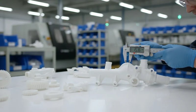
計算 投影面積1 は、あらゆる 射出成形2 投影。これを誤ると、以下のリスクがあります フラッシュ3 不良品の発生、機械の損傷、金型への充填不足などです。正しく計算できれば、適切なプレス機を自信を持って選定し、締付け力を推定し、初日から高品質な部品を生産できます。
当社の上海工場では、90トンから1850トンまでの47台の射出成形機を稼働しています。すべてのプロジェクトは同じ質問から始まります:投影面積はどれくらいか、そして当社の設備には十分な型締力があるか?このガイドでは、実際の計算式、実例、そして20年の生産経験に基づく実践的なヒントを通じて、計算プロセスを詳しく説明します。
- 投影面積とは、型締方向から見た部品の2次元シルエットです
- クランプ力 = 投影面積 × キャビティ内圧 × 安全係数
- 計算には常にランナーとゲートの面積を含めてください
- 複雑な形状は単純な幾何学的形状に分解できます
- 10-20%の安全余裕はフラッシュとショートショットを防止します
射出成形における投影面積とは何ですか?
射出成形における投影面積とは、金型が閉じる方向から部品を見たときの、部品の二次元の影またはシルエットです。懐中電灯を物体の真上から照らすことを想像してください。机に映る影がその投影面積です。この測定値は、通常平方センチメートル (cm²) または平方インチ (in) で表され、射出中に金型を密閉状態に保つために機械が必要とする型締力の大きさを直接決定します。
より広い視点では、当社の injection molding complete guide プロセスの基礎、材料挙動、生産判断について説明します。
If you are comparing vendors or planning procurement, our injection molding supplier sourcing guide covers RFQ prep, qualification, and commercial risk checks.
Why does it matter so much? When molten plastic enters the mold cavity under high pressure, it generates an outward force proportional to the projected area. If the machine’s clamping force is less than this outward force, the mold will open slightly at the parting line, causing flash — thin, unwanted fins of plastic along the edges of your part. In production environments, flash means rework, scrap, or rejected parts.
当社の上海工場では、90トンから1850トンまでの47台の射出成形機を稼働しています。すべての新規プロジェクトは、十分な型締容量を持つプレス機を選択するために投影面積を計算することから始まります。この単一の計算により、生産現場でのコストのかかる試行錯誤を防ぎます。
投影面積はどのように段階的に計算しますか?
投影面積は、部品を基本的な幾何学的形状に分解し、各シルエットを測定し、結果を合算することで計算されます。以下に、当社のステップバイステップ手法を示します。
ステップ1:クランプ方向を決定する
測定前に、金型が開閉する方向を特定します。これは通常、パーティングラインに垂直です。投影面積はこの軸に沿って測定されます。ほとんどの標準部品では、これはプラテンが動く方向です。
ステップ2:部品を単純な幾何学的形状に分解する
クランプ方向から部品を見てください。その外形を基本的な形状(長方形、円形、三角形、台形)に分解します。各形状には既知の面積公式があります:
必要な基本公式は以下の通りです:長方形 = 縦 × 横(例:50 mm × 30 mm = 1,500 平方mm);円 = π × 半径の2乗(例:π × 20の2乗 = 1,257 平方mm);三角形 = 0.5 × 底辺 × 高さ(例:0.5 × 40 × 25 = 500 平方mm);台形 = 0.5 × (a + b) × h(例:0.5 × (30 + 50) × 20 = 800 平方mm)。
ステップ3:各形状を計算し合計する
各サブ形状に適切な公式を適用し、すべての面積を合計します。長方形に半円形のタブが付いた部品の場合、長方形の面積と半円の面積を計算して加算します。
ステップ4:ランナーおよびゲート面積を加算する
ランナーシステムを忘れてはいけません。溶融プラスチックはキャビティに入る前にランナーとゲートを通ります。これらの流路も金型に対して外向きの力を発生させます。総面積にはランナーの投影面積を含めてください。多キャビティ金型では、単一キャビティの面積をキャビティ数で乗算し、その後ランナーの全面積を加算します。
ステップ5:抜き勾配補正を適用する(必要な場合)
大きな抜き勾配を持つ部品の場合、投影面積は平面での測定値と異なることがあります。ほとんどの抜き勾配(1〜3度)は影響を無視できますが、5度以上の抜き勾配を持つ深絞り部品では、傾斜した壁を考慮してシルエットを再計算してください。実際には、この補正が総面積の2〜3%を超えることはほとんどありません。
投影面積からのクランプ力の公式は何ですか?
投影面積が分かれば、締付け力の計算式が適切な機械選定の鍵となります。基本となる式は以下の通りです:
型締力 (kgf) = 投影面積 (cm²) × キャビティ内圧力 (kgf/cm²)
トンへの変換(1トン = 1,000 kgfの場合):
トンネージ = [投影面積 (cm²) × キャビティ内圧力 (kgf/cm²)] ÷ 1,000
キャビティ内圧力は成形される材料によって異なります。以下に、一般的な材料の典型的なキャビティ内圧力の値を示します:
| 素材 | キャビティ内圧 (kgf/cm2) | キャビティ内圧力 (トン/平方インチ) |
|---|---|---|
| PS(ポリスチレン) | 150–250 | 1.0–1.7 |
| PE(ポリエチレン) | 200–300 | 1.4–2.1 |
| PP(ポリプロピレン) | 200–350 | 1.4–2.5 |
| ABS | 300–500 | 2.1–3.5 |
| PA(ナイロン) | 350–600 | 2.5–4.2 |
| PC(ポリカーボネート) | 400–700 | 2.8–4.9 |
| POM (Acetal) | 350–550 | 2.5–3.9 |
| PBT | 350–550 | 2.5–3.9 |
計算されたトン数には常に1.1から1.2の安全係数を適用してください。これは粘度変動、金型温度変化、およびプロセス調整に対応します。私たちの実践では、通常15%の安全マージンを使用します。
一般的な部品形状の投影面積はどのように計算しますか?
一般的な形状は標準的な幾何学を使用します:矩形は長さ×幅、円はπ×半径²、複雑な部品は分解します。
例1:平面矩形部品
120mm×80mmの平らなカバープレートです。金型は薄肉方向(厚さ方向)でクランプされるため、投影面積は単に表面積となります:
投影面積 = 120 mm × 80 mm = 9,600 mm² = 96 cm²
ABSで成形する場合(キャビティ圧力 ≈ 400 kgf/cm²)、必要なトンネージは:トンネージ = (96 cm² × 400 kgf/cm²) ÷ 1,000 = 38.4 トン。安全率1.15を考慮:38.4 × 1.15 = 44.2 トン。50トンプレス機で余裕を持って対応可能です。
例2:円筒部品
外径60mmの円筒ブッシュです。投影面積は円形となります:
投影面積 = π × r² = 3.14159 × 30² = 2,827 mm² = 28.3 cm²
注意:シリンダーが中空の場合、投影面積から内径を差し引いてはいけません。クランプ力は壁の断面積だけでなく、完全な円形シルエット全体に作用します。
例3:L字ブラケット
L型ブラケットは2つの長方形に分割できます:長方形A(60 × 40 mm)と長方形B(40 × 30 mm)。2つの長方形が40 × 30 mmで重なる場合、合計面積は:
投影面積 = (60 × 40) + (40 × 30) – (40 × 30) = 2,400 mm² = 24 cm²
重要な原則:複雑な形状については、単純な形状に分解し、各面積を計算し、重複領域を減算しながら合計します。
投影面積の計算に影響する要因は何ですか?
投影面積の精度は4つの要素によって決定されます:部品形状、キャビティ数、ラナー設計、およびスライドやリフターなどの金型機能。
部品形状の複雑さ
リブ、突起、アンダーカット、および変化する肉厚を持つ複雑な部品は、単純な矩形や円ではない投影形状を作ります。CADソフトウェアを使用して3Dモデルから正確な投影面積を抽出してください。最新のCADパッケージ(SolidWorks、Creo、NX)は任意の軸方向の投影面積を自動計算できます。
キャビティ数
多キャビティ金型では、総投影面積は単一キャビティの投影面積をキャビティ数で乗算し、ラナーシステムの面積を加算します。単一キャビティ面積50 cm²、ラナー面積20 cm²の4キャビティ金型の総投影面積は(4 × 50)+ 20 = 220 cm²です。
ランナーシステム設計
コールドランナーは投影面積を大幅に増加させます。直径8mmの完全円形ランナーが金型内で150mm走行する場合、投影面積に12cm²を追加します。ホットランナーシステムは高価ですが、コールドランナーチャネルを排除することで投影面積を削減でき、場合によってはより小型で低コストのプレス機の使用を可能にします。
金設計の特徴
スライド、リフター、コアプルは有効投影面積を変化させます。特に側面動作スライドは、上面図からすぐには明らかではない角度で追加の投影面積を導入します。常に完全な 金型設計 工具エンジニアと相談してください。

「多キャビティ金型では、投影面積計算にラナー面積を含める必要があります。」真
ランナーシステムは総投影面積の10~25%を占めます。これを省略するとトンネージを過小評価し、フラッシュや金型分離を引き起こします。
「中空円筒部品の投影面積から内径を差し引くべきです。」偽
クランプ力は部品の完全な円形シルエット(中空内部を含む)に作用します。キャビティ内圧力は壁断面だけでなく、投影面積全体に対して外側に押し出します。
投影面積は機械選定にどのように影響するか?
必要な成形機トンネージは投影面積に直接比例します。過小評価するとフラッシュ、ショートショット、寸法不良を生じます。
90Tから1850Tまでのマシンフリートを所有しているため、ほぼすべてのプロジェクトに適したプレス機を選定できます。以下は計算式に基づくマシン選定の方法です:
射出機を選定する際は、プラテンサイズも考慮してください。金型は射出機プラテン内に収まり、投影面積はプラテン総面積の約三分の二を超えないようにします。投影面積がプラテンの70%以上を占める場合、締め付け力分布が不均一になり、隅でのフラッシュ発生リスクが増加します。もう一つの要素はティーバー間隔です:ティーバーに対して幅が広すぎる金型は、トン数に関係なく取り付けできません。試作または生産を決定する前に、常に金型寸法と投影面積を射出機仕様書と照合してください。
| 総投影面積(cm2) | 素材 | 必要トン数(トン) | 推奨射出機範囲 |
|---|---|---|---|
| < 100 | PP/PE | 15–35 | 90T |
| 100–300 | ABS/PA | 40–120 | 120T–200T |
| 300–800 | PC/POM | 120–350 | 200T–500T |
| 800–2,000 | PA/PC | 350–800 | 500T–1000T |
| > 2,000 | いろいろ | 800+ | 1000T–1850T |
当社の社内金型製造施設では月に100セット以上の金型を製造可能であり、DFM(設計段階での製造性検討)フェーズで投影面積の計算を迅速に検証し、鋼材が切削される前に金型設計を調整することができます。これにより時間を節約し、生産試作時のコストのかかる不具合を防ぎます。

What Are the Common Mistakes in Projected Area Calculations?
The top mistakes are omitting runner area, skipping safety factors, measuring the wrong axis, and ignoring undercuts. We have corrected all of these in production.
Forgetting the Runner Area
This is the number one mistake. Engineers calculate the part area perfectly but forget that the runner system also contributes to the clamping force requirement. In multi-cavity molds, the runner area can add 10-25% to the total. Always include it.
Ignoring the Safety Factor
Running a machine at exactly 100% of its rated tonnage leaves no margin for process variation. Material viscosity changes, mold temperature fluctuations, and injection speed adjustments all affect the actual force. A 10-20% safety factor is not optional — it is essential.
Measuring the Wrong Dimension
For non-symmetric parts, the projected area changes depending on which direction the mold opens. A part might have a small projected area in one orientation and a large one in another. Always measure along the actual clamp direction of the intended mold design.
Not Accounting for Undercuts
Parts with undercuts or side features can have additional projected area that is not visible from the primary clamp direction. Side-action slides transmit force at angles, creating vector components that add to the total clamping requirement.
How to Use CAD Software to Calculate Projected Area?
The fastest way to get projected area is using CAD software. SolidWorks, Creo, and NX compute the silhouette along any axis in seconds.
“A safety factor of 10-20% above calculated tonnage is standard practice in injection molding.”真
This margin accounts for material viscosity changes, mold temperature fluctuations, and normal machine wear. Running at 100% rated capacity leaves no room for process adjustments.
“Using a machine with twice the required tonnage always produces better quality parts.”偽
Oversized presses waste energy, increase cycle time due to larger platens, and can cause excessive compression on the mold, leading to premature wear on parting lines and ejector pins.
In SolidWorks, use the Measure tool with the projected area option, selecting the plane perpendicular to the clamp direction. In Creo (Pro/E), use the Analysis → Measure → Area tool with projection enabled. In Siemens NX, the Measure Faces command includes a projection direction option.
These tools give you the precise projected area in seconds, including complex organic shapes, fillets, and draft angles. We always cross-check CAD results with manual calculations for critical applications — it takes 30 extra seconds and catches potential errors.
What Is the Relationship Between Projected Area and Part Quality?
The projected area does not just affect machine selection — it has a direct impact on part quality and dimensional tolerance. Underestimating the projected area (and consequently the required tonnage) leads to several quality issues.
Flash is the most obvious symptom. When clamping force is insufficient, the mold separates at the parting line by even a few hundredths of a millimeter, and molten plastic escapes. Beyond flash, insufficient tonnage can cause dimensional instability — the part thickness varies because the mold is flexing under injection pressure. In severe cases, it leads to part weight variation and sink marks.
Conversely, grossly overestimating the projected area and using an oversized press wastes energy, increases cycle time (larger platens take longer to open and close), and can cause excessive compression on the mold, leading to premature wear on parting lines, ejector pins, and out-of-tolerance dimensions.
The sweet spot is 80-90% of the machine’s rated tonnage. This gives you adequate clamping force with some headroom for process adjustment while avoiding the inefficiencies of an oversized press.
How to Optimize Part Design to Reduce Projected Area?
Sometimes the projected area is too large for the available machine. Before investing in a larger press, consider these design optimizations to reduce the projected area.
Redesign the parting line. Moving the parting line can change which features are projected along the clamp axis. A part oriented at a different angle in the mold may have a significantly smaller projected area.
Reduce the number of cavities. If a four-cavity mold requires too much tonnage, a two-cavity mold halves the part-related projected area. You sacrifice throughput, but it may be more economical than buying a larger machine.
Switch to a hot runner system. Eliminating cold runners removes their contribution to the projected area. In tight-margin calculations, this alone can make the difference between fitting on a 500T press versus needing a 650T machine.
Consider insert molding or overmolding. These techniques can reduce the size of each individual shot while still producing a complex finished part through multiple operations on smaller machines. Insert molding also lets you combine metal inserts with plastic features in a single operation, eliminating secondary assembly steps and reducing overall production costs while keeping the projected area manageable for standard tonnage machines.
Another effective strategy is to modify the gate location. Moving the gate closer to the center of the part can reduce the flow length, which in turn reduces the required injection pressure and clamping force. Symmetrical gate placement also distributes pressure more evenly across the cavity, further minimizing the risk of flash and ensuring consistent part quality across the entire projected area.
With 20+ years of experience across 400+ plastic materials, our engineering team routinely helps customers optimize part designs and mold layouts to minimize projected area — often reducing required machine tonnage by 20-30% without sacrificing part quality.
What Are the Most Common Questions About Projected Area in Injection Molding?
よくある質問
What is the projected area in injection molding?
The projected area in injection molding is the two-dimensional silhouette of a part when viewed along the clamp direction. It represents the maximum cross-sectional area that the molten plastic pushes against during the injection process, and it directly determines the clamping force required to keep the mold closed during filling and packing. Engineers calculate it by measuring the outline of the part from the mold closing direction and converting the result to square centimeters or square inches. This measurement is essential for proper machine selection.
How do you calculate clamping force from projected area?
Clamping force equals the total projected area — including both the part cavity and the runner system — multiplied by the cavity pressure of the material being molded, divided by 1,000 to convert from kilograms-force to metric tons. For example, a part with 150 cm² of projected area molded in ABS at 400 kgf/cm² requires (150 × 400) ÷ 1,000 = 60 tons of clamping force. Engineers always add a safety factor of 10 to 20 percent to account for viscosity changes, temperature fluctuations, and normal process variation during production runs.
Does runner area affect projected area calculation?
Yes, the runner system absolutely affects the total projected area and must be included in every tonnage calculation. The clamping force must resist the injection pressure acting on both the cavity and the runner channels. In multi-cavity molds, the runner area can add 10 to 25 percent to the total projected area. For critical production applications, engineers must include the full runner layout in the calculation to avoid underestimating tonnage, which would cause flash and dimensional defects on the production floor.
What happens if the machine tonnage is too low for the projected area?
When the machine tonnage is insufficient for the projected area, the mold separates slightly at the parting line during the high-pressure injection phase. This separation causes flash — thin fins of plastic that escape along the part edges and require secondary trimming or cause part rejection. In more severe cases, insufficient clamping leads to dimensional variation across the parting line, short shots where the mold does not fill completely, and inconsistent part weight from shot to shot. Selecting a machine with at least 10 to 20 percent more tonnage than calculated prevents these costly production issues.
How do you calculate projected area for complex shapes?
For complex shapes, decompose the geometry into simple forms — rectangles, circles, and triangles — then calculate each area separately using standard geometric formulas. Sum all sub-areas while subtracting any overlapping regions to get the total. For organic or freeform surfaces, use CAD software with the projected area measurement tool, which computes the precise silhouette area along any specified direction in seconds. Most modern CAD packages such as SolidWorks, Creo, and NX include this functionality as a built-in measurement feature for injection mold designers.
What is the safety factor for injection molding tonnage?
The standard safety factor for injection molding tonnage is 1.1 to 1.2, meaning the selected machine should be rated 10 to 20 percent above the calculated clamping force. This margin accounts for material viscosity fluctuations between batches, mold temperature changes during extended production runs, injection speed adjustments during process optimization, and normal hydraulic system wear over time. Operating a machine at exactly its rated capacity leaves no room for the process adjustments that are routinely needed to maintain consistent part quality throughout a production run.
Can projected area calculation reduce manufacturing costs?
正確な投影面積計算は、主に機械サイズの過剰指定を防ぐことで製造コストを削減し、時間単価とエネルギー消費に直接影響します。不要な350トンプレスの代わりに200トンプレスで部品を成形すると、エネルギーを節約し、ジョブに課金される機械時間単価を下げ、小さなプラテンは開閉が速いため、多くの場合サイクルタイムを短縮します。投影面積を最小限に抑えるために部品の向き、ランナー設計、キャビティレイアウトを最適化することは、金型設計段階で利用できる最も費用対効果の高い戦略の一つです。
投影面積と部品表面積は同じですか?
いいえ、投影面積と表面積は根本的に異なる測定値です。表面積は、あらゆる輪郭、リブ、ボスを含む三次元部品のすべての外部表面の総面積です。投影面積は、クランプ方向という特定の方向から見た二次元のシルエットに過ぎません。表面積が1,256 cm²の球体は、どの角度から見ても投影面積は約400 cm²しかありません。射出成形に必要なクランプ力は、成形部品の総表面積ではなく、投影面積に依存します。
より良い射出成形結果を得るために、投影面積計算をマスターするにはどうすればよいですか?
投影面積の計算は、適切な機械選定、金型設計、生産品質の基礎です。計算式はシンプルです:クランプ方向に沿ったシルエット面積を測定し、ランナー面積を加え、キャビティ圧力を掛け、1.1〜1.2の安全率を適用します。
シンプルなブラケットであろうと、複雑な多キャビティ部品であろうと 射出成形金型この計算を正確に行うことで、時間を節約し、不良を防止し、生産コストを管理下に保つことができます。
ZetarMoldでは、エンジニアリングチームが各プロジェクトに20年以上の実践的な経験をもたらします。DFMレビューから生産最適化まで、投影面積を最初から正確に把握できるようサポートします。これにより、最初のショットから完璧な部品が得られます。
射出成形プロジェクトでお困りですか? 当社のエンジニアリングチームから、DFMフィードバック、正確なトンネージ計算、競争力のある価格を入手できます。


