Bir projede izdüşüm alanını1 hesaplamak, her enjeksiyon kalıplama2 çalışmasının ilk ve en kritik adımlarından biridir. Yanlış hesaplarsanız çapak3 kusuru, makine hasarı veya kalıbın dolmaması riskiyle karşılaşırsınız. Doğru hesaplarsanız uygun presi güvenle seçebilir, kapama kuvvetini tahmin edebilir ve ilk günden itibaren kaliteli parçalar üretebilirsiniz.
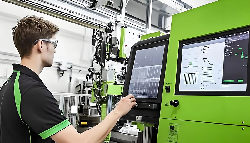
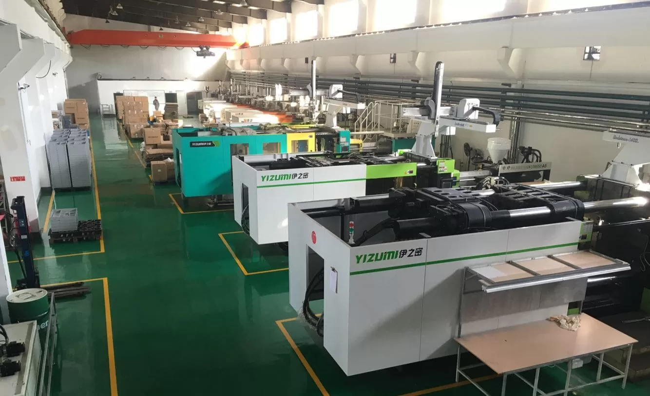
Şangay fabrikamızda, 90T’den 1850T’ye kadar değişen 47 enjeksiyon kalıplama makinesi çalıştırıyoruz. Her bir proje aynı soruyla başlar: izdüşüm alanı nedir ve ekipmanımız yeterli kapatma kuvvetine sahip mi? Bu kılavuz, gerçek formüllerle, çalışılmış örneklerle ve iki on yıllık üretim deneyiminden pratik ipuçlarıyla hesaplama sürecinde size yol gösterir.
- Projeksiyon alanı, parçanızın kapatma yönündeki 2B siluetidir
- Kapatma Kuvveti = Projeksiyon Alanı × Boşluk Basıncı × Güvenlik Faktörü
- Hesaplamanıza her zaman besleyici ve geçit alanlarını dahil edin
- Karmaşık şekiller daha basit geometrik formlara ayrılabilir
- 10-20% güvenlik payı, taşma ve eksik dolumu önler
Enjeksiyon Kalıplamada İzdüşüm Alanı Nedir?
Enjeksiyon kalıplamada projeksiyon alanı, kalıbın kapandığı yönden bakıldığında parçanızın iki boyutlu gölgesi veya siluetidir. Bir nesnenin üzerine doğrudan bir el feneri tutmayı düşünün — masaya düşen gölgesi onun projeksiyon alanıdır. Genellikle santimetrekare (cm²) veya inç kare (in²) olarak ifade edilen bu ölçüm, enjeksiyon sırasında kalıbın kapalı kalması için makinenizin ne kadar kapatma kuvvetine ihtiyaç duyduğunu doğrudan belirler.
Daha geniş bir bakış için enjeksiyon kalıplama eksiksiz kılavuzumuz süreç temellerini, malzeme davranışını ve üretim kararlarını ele alır.
Tedarikçileri karşılaştırıyor veya satın alma planlıyorsanız enjeksiyon kalıplama tedarikçisi bulma kılavuzumuz; RFQ hazırlığını, yeterlilik değerlendirmesini ve ticari risk kontrollerini ele alır.
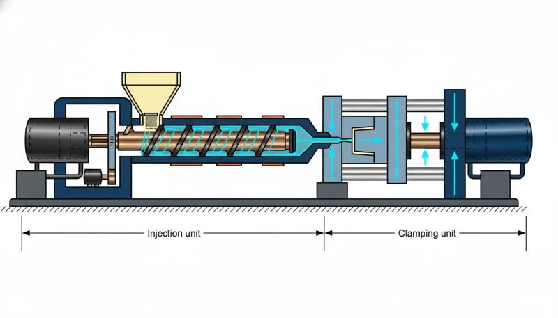
Neden bu kadar önemlidir? Eriyik plastik kalıp boşluğuna yüksek basınçla girdiğinde, izdüşüm alanıyla orantılı dışa doğru bir kuvvet üretir. Makinenin sıkma kuvveti bu dış kuvvetten düşükse kalıp ayırma hattında hafifçe açılır ve parçanın kenarlarında ince, istenmeyen plastik kanatlar olan çapak oluşur. Üretim ortamında çapak; yeniden işleme, hurda veya reddedilen parça demektir.
Şangay fabrikamızda, 90T'den 1850T'ye kadar 47 enjeksiyon kalıplama makinesi çalıştırıyoruz. Her yeni proje, yeterli kapatma kapasitesine sahip bir pres seçtiğimizden emin olmak için izdüşüm alanı hesaplanarak başlar — bu tek hesaplama, üretim alanında maliyetli deneme-yanılmayı önler.
Projeksiyon Alanı Nasıl Adım Adım Hesaplanır?
Projeksiyon alanı, parçayı temel geometrik şekillere ayırarak, her silueti ölçerek ve sonuçları toplayarak hesaplanır. İşte adım adım yöntemimiz.
Adım 1: Kapatma Yönünü Belirleyin
Herhangi bir ölçüm yapmadan önce, kalıbın hangi yönde açılıp kapandığını belirleyin. Bu genellikle ayırma çizgisine diktir. Projeksiyon alanı bu eksen boyunca ölçülür. Çoğu standart parça için bu, plakaların hareket ettiği yöndür.
Adım 2: Parçayı Basit Geometrik Şekillere Ayırın
Parçaya kapatma yönünden bakın. Dış hatlarını temel şekillere — dikdörtgenler, daireler, üçgenler ve yamuklar — bölün. Her şeklin bilinen bir alan formülü vardır:
İhtiyacınız olacak temel formüller şunlardır: Dikdörtgen = Uzunluk x Genişlik (örn., 50 mm x 30 mm = 1.500 mm²); Daire = pi x yarıçapın karesi (örn., pi x 20² = 1.257 mm²); Üçgen = 0,5 x Taban x Yükseklik (örn., 0,5 x 40 x 25 = 500 mm²); Yamuk = 0,5 x (a + b) x h (örn., 0,5 x (30 + 50) x 20 = 800 mm²).
Adım 3: Her Şekli Hesaplayın ve Toplayın
Uygun formülü her bir alt şekle uygulayın, ardından tüm alanları toplayın. Dikdörtgen ve yarım daire şeklinde bir çıkıntıya sahip bir parça için dikdörtgen alanı, yarım daire alanını hesaplar ve toplarsınız.
Adım 4: Besleyici ve Geçit Alanlarını Ekleyin
Besleyici sistemini unutmayın. Eriyik plastik, boşluğa girmeden önce besleyiciler ve geçitlerden geçer. Bu kanallar da kalıp üzerinde dışa doğru kuvvet oluşturur. Toplamınıza besleyici izdüşüm alanını dahil edin. Çoklu boşluklu kalıplarda, tek boşluk alanını boşluk sayısıyla çarpın, ardından tam besleyici alanını ekleyin.
Adım 5: Pah Düzeltmesi Uygulayın (Gerekirse)
Önemli pah açılarına sahip parçalarda, projeksiyon alanı düz alan ölçümünden farklı olabilir. Çoğu pah açısı (1-3 derece) ihmal edilebilir etkiye sahiptir, ancak 5+ derece pah açısına sahip derin çekme parçalar için açılı duvarları hesaba katarak silueti yeniden hesaplayın. Pratikte bu düzeltme genellikle toplam alanın %2-3’ünü geçmez.
Projeksiyon Alanından Kapatma Kuvveti Formülü Nedir?
Projeksiyon alanını elde ettikten sonra, doğru makineyi seçmek için kapatma kuvveti formülü anahtardır. Temel denklem şudur:
Kapatma Kuvveti (kgf) = Projeksiyon Alanı (cm²) × Kalıp İçi Basınç (kgf/cm²)
Tona dönüştürme (1 ton = 1.000 kgf):
Tonaj = [Projeksiyon Alanı (cm²) × Kalıp İçi Basınç (kgf/cm²)] ÷ 1.000
Kalıp içi basıncı, kullanılan malzemeye bağlıdır. İşte yaygın malzemeler için tipik kalıp içi basınç değerleri:
| Malzeme | Boşluk Basıncı (kgf/cm²) | Boşluk Basıncı (ton/inç²) |
|---|---|---|
| PS (Polistiren) | 150–250 | 1.0–1.7 |
| PE (Polietilen) | 200–300 | 1.4–2.1 |
| PP (Polipropilen) | 200–350 | 1.4–2.5 |
| ABS | 300–500 | 2.1–3.5 |
| PA (Naylon) | 350–600 | 2.5–4.2 |
| PC (Polikarbonat) | 400–700 | 2.8–4.9 |
| POM (Asetal) | 350–550 | 2.5–3.9 |
| PBT | 350–550 | 2.5–3.9 |
Hesaplanan tonaja daima 1.1 ila 1.2 arasında bir güvenlik faktörü uygulayın. Bu, viskozite değişimlerini, kalıp sıcaklığı değişikliklerini ve proses ayarlamalarını hesaba katar. Uygulamalarımızda genellikle %15 güvenlik payı kullanırız.
Yaygın Parça Şekilleri için Projeksiyon Alanı Nasıl Hesaplanır?
Yaygın şekiller standart geometri kullanır: dikdörtgenler için uzunluk çarpı genişlik, daireler için pi çarpı yarıçapın karesi ve karmaşık parçalar için ayrıştırma.
Örnek 1: Düz Dikdörtgen Parça
Düz bir kapak plakası 120 mm × 80 mm ölçülerindedir. Kalıp ince ölçü (kalınlık yönü) boyunca kapanır, dolayısıyla izdüşüm alanı doğrudan yüzey alanıdır:
İzdüşüm Alanı = 120 mm × 80 mm = 9,600 mm² = 96 cm²
ABS ile kalıplanırsa (kalıp boşluğu basıncı ≈ 400 kgf/cm²), gereken tonaj şöyle olur: Tonaj = (96 cm² × 400 kgf/cm²) ÷ 1,000 = 38.4 ton. 15% güvenlik faktörüyle: 38.4 × 1.15 = 44.2 ton. 50 tonluk bir pres bunu rahatlıkla karşılar.
Örnek 2: Silindirik Parça
Dış çapı 60 mm olan silindirik bir burç. İzdüşüm alanı bir dairedir:
İzdüşüm Alanı = π × r = 3.14159 × 30 = 2,827 mm² = 28.3 cm²
Not: silindir içi boşsa iç deliği izdüşüm alanından ÇIKARMAYIN. Bağlama kuvveti yalnızca et kesitine değil, dairesel siluetin tamamına etki eder.
Örnek 3: L Biçimli Braket
L biçimli bir braket iki dikdörtgene ayrılabilir: Dikdörtgen A (60 × 40 mm) ve Dikdörtgen B (40 × 30 mm). İki dikdörtgen 40 × 30 mm kadar örtüşüyorsa toplam şöyledir:
İzdüşüm Alanı = (60 × 40) + (40 × 30) - (40 × 30) = 2,400 mm² = 24 cm²
Temel ilke: Karmaşık bir şekli basit şekillere ayırın, her alanı hesaplayın ve çakışan bölgeleri çıkararak tümünü toplayın.
Projeksiyon Alanı Hesaplamasını Hangi Faktörler Etkiler?
İzdüşüm alanının doğruluğunu dört etken belirler: parça geometrisi, göz sayısı, yolluk tasarımı ve sürgüler ile kaldırıcılar gibi kalıp özellikleri.
Parça Geometrisi Karmaşıklığı
Federler, bosslar, ters açılar ve değişken duvar kalınlıkları içeren karmaşık parçaların izdüşümleri basit dikdörtgen veya daire değildir. 3D modelinizden hassas izdüşüm alanını çıkarmak için CAD yazılımı kullanın. Çoğu modern CAD paketi (SolidWorks, Creo, NX), herhangi bir eksendeki izdüşüm alanını otomatik olarak hesaplayabilir.
Boşluk Sayısı
Çok gözlü kalıplarda toplam izdüşüm alanı; tek gözün izdüşüm alanının göz sayısıyla çarpımına yolluk sistemi alanının eklenmesiyle bulunur. Tek göz alanı 50 cm² ve yolluk alanı 20 cm² olan dört gözlü bir kalıbın toplam izdüşüm alanı (4 × 50) + 20 = 220 cm²’dir.
Koşucu Sistem Tasarımı
Soğuk yolluklar önemli alan ekler. Kalıp boyunca 150 mm uzanan, 8 mm çaplı tam yuvarlak bir yolluk izdüşüm alana 12 cm² ekler. Sıcak yolluk sistemleri daha pahalı olsa da soğuk yolluk kanalını ortadan kaldırarak izdüşüm alanı azaltır; bu bazen daha küçük ve daha ucuz bir pres kullanılmasına olanak tanır.
Kalıp Tasarım Özellikleri
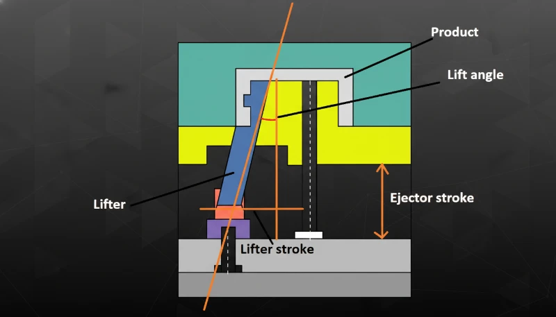
Sürgüler, eğik iticiler ve maça çekiciler etkin izdüşüm alanını değiştirebilir. Özellikle yandan hareketli sürgüler, üstten görünüşte hemen fark edilmeyen açılarda ek izdüşüm alanı oluşturabilir. Kalıp tasarımının tamamını daima takım mühendisinizle birlikte inceleyin.
"Çok gözlü kalıplarda yolluk alanı, izdüşüm alanı hesaplarına dâhil edilmelidir."True
Yolluk sistemi toplam izdüşüm alanının 10-25%'ini oluşturur. Bunun hesaba katılmaması tonajın düşük tahmin edilmesine, enjeksiyon sırasında çapak oluşmasına ve kalıbın ayrılmasına yol açar.
"İçi boş silindirik bir parçanın izdüşüm alanından iç deliği çıkarmalısınız."False
Kapama kuvveti, içindeki boşluk dâhil parçanın tam dairesel silüetine etki eder. Kavite basıncı yalnızca cidar kesitine değil, izdüşüm alanının tamamına karşı dışarı doğru iter.
Projeksiyon Alanı Makine Seçimini Nasıl Etkiler?
Gerekli makine tonajı, izdüşüm alanıyla doğru orantılıdır. Yetersiz boyutlandırma üretimde çapağa, eksik doluma ve ölçü kusurlarına yol açar.
90T ile 1850T arasındaki makine parkımız sayesinde hemen her projeyi doğru presle eşleştirebiliriz. Hesabın makine seçimine nasıl dönüştüğü aşağıda açıklanmıştır:
Bir makine seçerken tabla boyutunu da göz önünde bulundurun. Kalıp makine tablasına sığmalı ve izdüşüm alanı toplam tabla alanının yaklaşık üçte ikisini aşmamalıdır. İzdüşüm alanınız tablanın 70%‘inden fazlasını kaplıyorsa kapama kuvveti dağılımı dengesizleşerek köşelerde çapak riskini artırır. Diğer bir faktör kolonlar arası mesafedir: kolonlara göre fazla geniş olan bir kalıp, tonajı ne olursa olsun monte edilemez. Bir prototip veya üretim çalışmasına karar vermeden önce kalıp ölçülerinizi ve izdüşüm alanınızı her zaman makine spesifikasyon sayfasıyla karşılaştırın.
| Toplam İzdüşüm Alanı (cm2) | Malzeme | Gerekli Tonaj (ton) | Önerilen Makine Aralığı |
|---|---|---|---|
| < 100 | PP/PE | 15–35 | 90T |
| 100–300 | ABS/PA | 40–120 | 120T–200T |
| 300–800 | PC/POM | 120–350 | 200T–500T |
| 800–2,000 | PA/PC | 350–800 | 500T–1000T |
| > 2,000 | Çeşitli | 800+ | 1000T–1850T |
Şirket içi kalıp üretim tesisimiz ayda 100+ kalıp setini destekler; bu sayede DFM aşamasında izdüşüm alanı hesaplarını hızla doğrulayıp daha çelik işlenmeden kalıp tasarımlarını ayarlayarak zaman kazanır ve üretim denemelerindeki maliyetli sürprizleri önleriz.
Projeksiyon Alanı Hesaplamalarında Yaygın Hatalar Nelerdir?
En yaygın hatalar yolluk alanını hesaba katmamak, emniyet katsayılarını atlamak, yanlış ekseni ölçmek ve ters açıları göz ardı etmektir. Üretimde bunların tümünü düzelttik.
Yolluk Alanını Unutmak
Bu en yaygın hatadır. Mühendisler parça alanını kusursuz hesaplar ancak yolluk sisteminin de bağlama kuvveti gereksinimine katkıda bulunduğunu unutur. Çok gözlü kalıplarda yolluk alanı toplam değere 10-25% ekleyebilir. Bunu daima hesaba katın.
Güvenlik Katsayısını Göz Ardı Etmek
Bir makineyi nominal tonajının tam 100%‘ünde çalıştırmak, proses değişkenliği için hiç pay bırakmaz. Malzeme viskozitesindeki değişimler, kalıp sıcaklığı dalgalanmaları ve enjeksiyon hızı ayarları gerçek kuvveti etkiler. 10-20% güvenlik katsayısı isteğe bağlı değil, zorunludur.
Yanlış Boyutun Ölçülmesi
Simetrik olmayan parçalarda izdüşüm alanı kalıbın açılma yönüne göre değişir. Bir parça bir yönde küçük, başka yönde büyük izdüşüm alanına sahip olabilir. Her zaman amaçlanan kalıp tasarımının gerçek kapama yönünde ölçüm yapın.
Ters Açıların Hesaba Katılmaması
Ters açılı veya yan özellikli parçalar, ana kilitleme yönünden görünmeyen ek izdüşüm alanına sahip olabilir. Yan hareket kızakları kuvveti açılı olarak iletir ve toplam kilitleme gereksinimine eklenen vektör bileşenleri oluşturur.
Projeksiyon Alanını Hesaplamak için CAD Yazılımı Nasıl Kullanılır?
İzdüşüm alanını elde etmenin en hızlı yolu CAD yazılımı kullanmaktır. SolidWorks, Creo ve NX, herhangi bir eksen boyunca silüeti saniyeler içinde hesaplar.
"Enjeksiyon kalıplamada hesaplanan tonajın 10-20% üzerinde bir güvenlik faktörü standart uygulamadır."True
Bu marj; malzeme viskozitesindeki değişimleri, kalıp sıcaklığındaki dalgalanmaları ve normal makine aşınmasını karşılar. Anma kapasitesinin 100% düzeyinde çalışmak, proses ayarlamaları için pay bırakmaz.
"Gereken tonajın iki katına sahip bir makine kullanmak her zaman daha kaliteli parçalar üretir."False
Gereğinden büyük presler enerji israf eder, büyük plakalar nedeniyle çevrim süresini uzatır ve kalıba aşırı basınç uygulayarak ayırma çizgileri ile itici pimlerin erken aşınmasına yol açabilir.
SolidWorks’te bağlama yönüne dik düzlemi seçerek izdüşüm alanı seçeneğiyle Measure aracını kullanın. Creo’da (Pro/E), izdüşümü etkinleştirerek Analysis → Measure → Area aracını kullanın. Siemens NX’te Measure Faces komutu bir izdüşüm yönü seçeneği içerir.
Bu araçlar; karmaşık organik şekiller, radyüsler ve draft açıları dâhil kesin izdüşüm alanını saniyeler içinde verir. Kritik uygulamalarda CAD sonuçlarını her zaman manuel hesaplamalarla çapraz kontrol ederiz — fazladan 30 saniye sürer ve olası hataları yakalar.
Projeksiyon Alanı ile Parça Kalitesi Arasındaki İlişki Nedir?
İzdüşüm alanı yalnızca makine seçimini etkilemez; parça kalitesi ve boyutsal tolerans üzerinde de doğrudan etkilidir. İzdüşüm alanını ve dolayısıyla gerekli tonajı düşük tahmin etmek çeşitli kalite sorunlarına yol açar.
Çapak en belirgin belirtidir. Kapama kuvveti yetersiz olduğunda kalıp, ayırma çizgisinde milimetrenin yalnızca birkaç yüzde biri kadar bile ayrılsa erimiş plastik dışarı kaçar. Çapağın yanı sıra yetersiz tonaj boyutsal kararsızlığa neden olabilir; kalıp enjeksiyon basıncı altında esnediği için parça kalınlığı değişir. Ağır durumlarda parça ağırlığı değişimine ve çökme izlerine yol açar.
Tersine, izdüşüm alanını ciddi ölçüde fazla tahmin edip gereğinden büyük bir pres kullanmak enerji harcar, çevrim süresini uzatır (daha büyük plakaların açılıp kapanması daha uzun sürer) ve kalıpta aşırı sıkıştırmaya neden olabilir. Bu da ayırma hatları, itici pimler ve tolerans dışı boyutlarda erken aşınmaya yol açar.
İdeal aralık, makinenin nominal tonajının 80-90% düzeyidir. Bu, aşırı büyük bir presin verimsizliklerinden kaçınırken süreç ayarı için bir miktar pay bırakarak yeterli kilitleme kuvveti sağlar.
İzdüşüm Alanını Azaltmak için Parça Tasarımı Nasıl Optimize Edilir?
Bazen izdüşüm alanı mevcut makine için çok büyüktür. Daha büyük bir prese yatırım yapmadan önce izdüşüm alanını azaltmak için bu tasarım optimizasyonlarını değerlendirin.
Ayırma çizgisini yeniden tasarlayın. Ayırma çizgisini taşımak, hangi özelliklerin kapama ekseni boyunca izdüşürüldüğünü değiştirebilir. Kalıpta farklı bir açıyla yönlendirilmiş bir parçanın izdüşüm alanı önemli ölçüde daha küçük olabilir.
Göz sayısını azaltın. Dört gözlü bir kalıp çok fazla tonaj gerektiriyorsa iki gözlü bir kalıp, parçadan kaynaklanan izdüşüm alanını yarıya indirir. Üretim hızından ödün verirsiniz, ancak bu çözüm daha büyük bir makine almaktan daha ekonomik olabilir.
Sıcak yolluk sistemine geçin. Soğuk yollukların ortadan kaldırılması, izdüşüm alanına katkılarını yok eder. Dar marjlı hesaplamalarda yalnızca bu değişiklik, 500T presin yeterli olması ile 650T makineye ihtiyaç duyulması arasındaki farkı yaratabilir.
Insert kalıplamayı veya üzeri kalıplamayı değerlendirin. Bu teknikler, daha küçük makinelerde birden fazla işlemle karmaşık bir nihai parça üretirken her baskının boyutunu küçültebilir. Insert kalıplama ayrıca metal insertleri plastik özelliklerle tek işlemde birleştirerek ikincil montaj adımlarını ortadan kaldırır, toplam üretim maliyetlerini düşürür ve izdüşüm alanını standart tonajlı makineler için yönetilebilir düzeyde tutar.
Bir diğer etkili strateji, yolluk girişinin konumunu değiştirmektir. Yolluk girişini parçanın merkezine yaklaştırmak akış uzunluğunu azaltabilir; bu da gerekli enjeksiyon basıncını ve sıkma kuvvetini düşürür. Simetrik yolluk girişi yerleşimi de basıncı kalıp boşluğuna daha eşit dağıtarak çapak riskini daha da azaltır ve izdüşüm alanının tamamında tutarlı parça kalitesi sağlar.
400+ plastik malzemeyi kapsayan 20+ yıllık deneyimiyle mühendislik ekibimiz, müşterilerin parça tasarımlarını ve kalıp yerleşimlerini izdüşüm alanını en aza indirecek şekilde optimize etmelerine düzenli olarak yardımcı olur; çoğu zaman parça kalitesinden ödün vermeden gereken makine tonajını %20-30 azaltır.
Enjeksiyon Kalıplamada Projeksiyon Alanı Hakkında En Yaygın Sorular Nelerdir?
Sıkça Sorulan Sorular
Enjeksiyon kalıplamada izdüşüm alanı nedir?
Enjeksiyon kalıplamada iz düşüm alanı, sıkma yönünden bakıldığında parçanın iki boyutlu siluetidir. Enjeksiyon sırasında erimiş plastiğin bastırdığı en büyük kesit alanını temsil eder ve dolum ile ütüleme boyunca kalıbı kapalı tutmak için gereken sıkma kuvvetini doğrudan belirler. Mühendisler bu alanı, kalıbın kapanma yönünden parçanın dış çizgisini ölçüp sonucu santimetrekare veya inçkareye dönüştürerek hesaplar. Bu ölçüm, doğru makine seçimi için gereklidir.
İz düşüm alanından kalıp kapama kuvveti nasıl hesaplanır?
Sıkma kuvveti; parça boşluğu ve yolluk sistemi dahil toplam izdüşüm alanının, kalıplanan malzemenin boşluk basıncıyla çarpılıp kilogram-kuvvetten metrik tona dönüştürmek için 1,000’e bölünmesiyle hesaplanır. Örneğin, 150 cm² izdüşüm alanına sahip bir parçanın ABS ile 400 kgf/cm² basınçta kalıplanması için (150 × 400) ÷ 1,000 = 60 tons sıkma kuvveti gerekir. Mühendisler üretim serilerindeki viskozite değişimlerini, sıcaklık dalgalanmalarını ve olağan proses değişkenliğini hesaba katmak için her zaman yüzde 10 ila 20 güvenlik katsayısı ekler.
Yolluk alanı izdüşüm alanı hesabını etkiler mi?
Evet, yolluk sistemi toplam izdüşüm alanını kesinlikle etkiler ve her tonaj hesabına dâhil edilmelidir. Kapama kuvveti, hem boşluğa hem de yolluk kanallarına etki eden enjeksiyon basıncına karşı koymalıdır. Çok gözlü kalıplarda yolluk alanı, toplam izdüşüm alanına yüzde 10 ila 25 ekleyebilir. Kritik üretim uygulamalarında mühendisler, tonajı düşük hesaplamaktan kaçınmak için yolluk düzeninin tamamını hesaba katmalıdır; aksi hâlde üretim sahasında çapak ve boyutsal kusurlar oluşur.
Makine tonajı izdüşüm alanı için çok düşükse ne olur?
Makine tonajı izdüşüm alanı için yetersiz olduğunda kalıp, yüksek basınçlı enjeksiyon aşamasında ayırma çizgisinde hafifçe açılır. Bu ayrılma, parça kenarlarından kaçan ve ikincil kırpma gerektiren ya da parçanın reddine yol açan ince plastik kanatlar biçiminde çapak oluşturur. Daha ağır durumlarda yetersiz bağlama; ayırma çizgisi boyunca boyutsal değişime, kalıbın tamamen dolmadığı eksik dolumlara ve çevrimden çevrime tutarsız parça ağırlığına neden olur. Hesaplanandan en az yüzde 10 ila 20 daha fazla tonaja sahip bir makine seçmek bu maliyetli üretim sorunlarını önler.
Karmaşık şekillerin izdüşüm alanı nasıl hesaplanır?
Karmaşık şekillerde geometriyi dikdörtgen, daire ve üçgen gibi basit biçimlere ayırın; ardından standart geometrik formüllerle her alanı ayrı hesaplayın. Toplamı bulmak için çakışan bölgeleri çıkararak tüm alt alanları toplayın. Organik veya serbest biçimli yüzeylerde, belirtilen herhangi bir yöndeki kesin siluet alanını saniyeler içinde hesaplayan izdüşüm alanı ölçüm aracına sahip CAD yazılımı kullanın. SolidWorks, Creo ve NX gibi çoğu modern CAD paketi, enjeksiyon kalıbı tasarımcıları için bu işlevi yerleşik ölçüm özelliği olarak sunar.
Enjeksiyon kalıplama tonajı için güvenlik katsayısı nedir?
Enjeksiyon kalıplama tonajı için standart güvenlik katsayısı 1.1 ila 1.2’dir; yani seçilen makinenin kapasitesi, hesaplanan kapama kuvvetinden yüzde 10 ila 20 yüksek olmalıdır. Bu pay; partiler arasındaki malzeme viskozitesi dalgalanmalarını, uzun üretim çalışmaları sırasındaki kalıp sıcaklığı değişimlerini, proses optimizasyonundaki enjeksiyon hızı ayarlarını ve hidrolik sistemin zamanla oluşan normal aşınmasını karşılar. Makineyi tam nominal kapasitesinde çalıştırmak, üretim boyunca tutarlı parça kalitesini korumak için rutin olarak gereken proses ayarlarına yer bırakmaz.
İzdüşüm alanı hesabı üretim maliyetlerini azaltabilir mi?
Doğru izdüşüm alanı hesabı, esas olarak makine boyutunun gereğinden büyük seçilmesini önleyerek üretim maliyetlerini düşürür; çünkü makine boyutu saatlik ücretleri ve enerji tüketimini doğrudan etkiler. Bir parçayı gereksiz bir 350 tonluk makine yerine 200 tonluk preste çalıştırmak enerji tasarrufu sağlar, işe yansıtılan makine saat ücretini düşürür ve daha küçük plakalar daha hızlı açılıp kapandığı için çoğu zaman çevrim sürelerini kısaltır. İzdüşüm alanını en aza indirmek üzere parça yönünü, yolluk tasarımını veya kalıp gözü yerleşimini optimize etmek, kalıp tasarımı aşamasındaki en uygun maliyetli stratejilerden biridir.
Projeksiyon alanı, parça yüzey alanıyla aynı mıdır?
Hayır, projeksiyon alanı ve yüzey alanı temelde farklı ölçümlerdir. Yüzey alanı, üç boyutlu bir parçanın tüm dış yüzeylerinin toplam alanıdır; her kontur, nervür ve kabarcık dahildir. Projeksiyon alanı ise sadece belirli bir yönden - kapatma yönünden - bakıldığında görülen iki boyutlu siluettir. 1.256 cm² yüzey alanına sahip bir kürenin, herhangi bir açıdan bakıldığında projeksiyon alanı sadece yaklaşık 400 cm²’dir. Enjeksiyon kalıplama için gereken kapatma kuvveti, kalıplanan bileşenin toplam yüzey alanına değil, projeksiyon alanına bağlıdır.
Daha İyi Enjeksiyon Kalıplama Sonuçları için Projeksiyon Alanı Hesaplamalarında Nasıl Uzmanlaşabilirsiniz?
Projeksiyon alanı hesaplaması, doğru makine seçimi, kalıp tasarımı ve üretim kalitesinin temelidir. Formül basittir: kapatma yönü boyunca siluet alanını ölçün, besleyici alanını ekleyin, boşluk basıncı ile çarpın ve 1.1–1.2 güvenlik faktörünü uygulayın.
İster basit bir braket ister karmaşık, çok gözlü bir enjeksiyon kalıbı tasarlayın; bu hesabı doğru yapmak zaman kazandırır, kusurları önler ve üretim maliyetlerinizi kontrol altında tutar.
ZetarMold’da mühendislik ekibimiz her projeye 20+ yıllık pratik deneyim getirir. DFM incelemesinden üretim optimizasyonuna kadar, projeksiyon alanını ilk seferde doğru yapmanıza yardımcı oluyoruz - böylece parçalarınız ilk atıştan mükemmel çıkıyor.
Enjeksiyon kalıplama projeniz için yardıma mı ihtiyacınız var? Mühendislik ekibimizden DFM geri bildirimi, doğru tonaj hesapları ve rekabetçi fiyat alın.
izdüşüm alanı: İzdüşüm alanı, üç boyutlu bir parçanın kalıp kapama yönünden bakıldığında görülen iki boyutlu siluetidir ve genellikle santimetrekare veya inçkare cinsinden ölçülür. ↩
enjeksiyon kalıplama: Enjeksiyon kalıplama, erimiş malzemenin bir kalıba enjekte edilmesiyle parça üreten ve plastik bileşenlerin seri üretiminde yaygın olarak kullanılan bir imalat sürecidir. ↩
çapak: Enjeksiyon kalıplamada çapak, enjeksiyon sırasında kalıp boşluğundan ayırma çizgisi boyunca kaçan ve parça yüzeyinde istenmeyen ince çıkıntılar oluşturan fazla malzemedir. ↩