 Zum Inhalt springen

Ihre Konstruktionsdatei gibt ±0,1 mm an. Ihr Spritzgießer bietet ±0,2 mm an. Ihr Kunde verlangt eine Ebenheit von 0,05 mm über die gesamte Dichtfläche. Drei verschiedene Zahlen – keine davon spricht dieselbe Sprache. Das ist das Kernproblem bei der Tolerierung in Spritzgießen: Lineare Abmessungen und geometrische Toleranzen sind nicht dasselbe, und ihre Verwechslung kann eine gesamte Produktionscharge kosten.
Dieser Leitfaden erklärt, was geometrische Toleranzen im Spritzguss tatsächlich bedeuten, wie GD&T-Symbole in Anforderungen an Form und Teil übersetzt werden und was Sie realistisch in der Produktion einhalten können – mit konkreten Zahlen, nicht vagen Bereichen.
- Geometrische Toleranzen steuern Form, Ausrichtung und Position – nicht nur Größe – und sind daher entscheidend für Dichtflächen, Pass teile und Baugruppen.
- Standardmäßige spritzgegossene Teile halten lineare Toleranzen von ±0,1–0,2 mm; kritische Merkmale können mit geeigneter Formkonstruktion und Materialauswahl ±0,05 mm erreichen.
- GD&T-Ebenheit, Rechtwinkligkeit und wahre Position sind die drei am häufigsten spezifizierten geometrischen Kontrollen in Zeichnungen von Kunststoffteilen.
- Schrumpfung, Verzug und Trennlinienversatz sind die drei Hauptursachen für Fehler bei geometrischen Toleranzen im Spritzguss.
- Die Angabe der GD&T-Ebenheit an Formtrennlinien reduziert Gratfehler um etwa 60 % im Vergleich zu alleinigen linearen Toleranzangaben.
Was sind geometrische Toleranzen beim Spritzgießen?
Geometrische Toleranzen im Spritzguss sind die Hauptkategorien oder Optionen, die in diesem Abschnitt erläutert werden. Wenn Sie Anbieter vergleichen oder die Beschaffung planen, unsere injection molding supplier sourcing guide covers RFQ prep, qualification, and commercial risk checks.
Geometrische Toleranzen definieren die zulässige Abweichung in Form, Ausrichtung, Lage und Rundlauf einer Geometrie – nicht nur ihrer Größe. Beim Spritzgießen kann ein Teil im Durchmesser innerhalb von ±0,1 mm liegen und trotzdem die Montage verfehlen, weil seine Passfläche um 0,3 mm nicht eben ist. Dieses Versagen ist ein geometrisches Toleranzproblem, kein dimensionales.
Das formale System zur Spezifikation geometrischer Toleranzen ist GD&T – Geometrische Bemaßung und Tolerierung – standardisiert nach ASME Y14.5 und ISO 1101. GD&T unterteilt Toleranzen in fünf Kategorien: Form (Ebenheit, Geradheit, Rundheit, Zylindrizität), Orientierung (Parallelität, Rechtwinkligkeit, Winkligkeit), Lage (wahre Position, Konzentrizität, Symmetrie), Lauf (Kreis-Lauf, Gesamtlauf) und Profil (Profil einer Linie, Profil einer Fläche).
Bei spritzgegossenen Teilen sind die am häufigsten angewendeten GD&T-Steuerungen Ebenheit (Dichtflächen, Montageflächen), wahre Position (Bolzenpositionen, Schnapphaken) und Rechtwinkligkeit (Wände, Rippen, Stifte). Jede dieser Toleranzen muss berücksichtigen, wie sich Kunststoff während des Abkühlens verhält – etwas, das eine rein dimensionale Angabe nicht erfassen kann.
Welche Toleranzniveaus kann Spritzguss tatsächlich halten?
Standard-Spritzguss in kommerzieller Qualität hält ±0,2 mm bei nicht-kritischen Merkmalen. Fein-Toleranz-Produktion erreicht ±0,05–0,1 mm bei kritischen Abmessungen mit kontrollierten Materialien und validierten Werkzeugen. Alles, was enger als ±0,05 mm ist, erfordert typischerweise nachträgliche Bearbeitung oder Präzisionswerkzeuge mit temperaturgeregelten Pressen.
Die SPI-Toleranzrichtlinien (Society of the Plastics Industry) kategorisieren Teile in drei Klassen. Die kommerzielle Klasse erlaubt ±0,25 mm bei den meisten Merkmalen und eignet sich für Konsumgüter. Die Fein-Klasse zielt auf ±0,13 mm für funktionale Komponenten ab. Die Präzisionsklasse strebt ±0,05 mm bei kritischen Merkmalen an und gilt für medizinische, Luft- und Raumfahrt- sowie automobiltechnische Dichtungsflächen.
Geometrische Toleranzen fügen eine weitere Ebene hinzu. Selbst wenn eine Abmessung innerhalb der Spezifikation liegt, kann die Form es nicht sein. Eine flache Bossfläche, die mit einer Ebenheit von 0,1 mm spezifiziert ist, ist weit anspruchsvoller als eine ±0,1 mm Abmessungsangabe – sie erfordert, dass die gesamte Oberfläche innerhalb einer 0,1 mm Toleranzzone liegt, unabhängig davon, wo das Teil dimensionell liegt.
| Tolerance Class | Lineare Toleranz | Ebenheit (GD&T) | Typische Anwendung |
|---|---|---|---|
| Kommerziell | ±0,25 mm | 0,4 mm | Consumer products, housings |
| Fein | ±0,13 mm | 0,2 mm | Mechanische Baugruppen, Steckverbinder |
| Präzision | ±0.05 mm | 0,08 mm | Medizinische Geräte, Automobildichtungen |
| Ultrapräzision | ±0.025 mm | 0,04 mm | Erfordert nachträgliche Bearbeitung |
Die Materialauswahl beeinflusst die Toleranzfähigkeit ebenso sehr wie die Werkzeuge. Amorphe Harze wie PC und ABS schrumpfen gleichmäßig und halten typischerweise engere Toleranzen. Teilkristalline Materialien wie Nylon und POM haben höhere und variablere Schrumpfung1 Raten, wodurch geometrische Kontrollen schwerer zu erreichen sind, ohne die Form auszugleichen.
Wie beeinflusst Kunststoffschrumpfung geometrische Toleranzen?
Schrumpfung ist die primäre Variable, die die Theorie der geometrischen Toleranzen von der Produktionsrealität trennt. Jedes Kunststoffmaterial schrumpft beim Übergang von der Schmelze zum Festkörper – typischerweise 0,1% bis 3% – und diese Schrumpfung ist nie perfekt gleichmäßig über ein komplexes Teil. Ungleichmäßige Schrumpfung erzeugt Verzug, was direkt gegen Ebenheits- und Rechtwinkligkeitsangaben verstößt.
Die Form wird absichtlich überdimensional ausgeführt, um Schrumpfung auszugleichen. Ein nominell 100 mm langes Teil mit einer Schrumpfungsrate von 0,5 % benötigt einen Formhohlraum von 100,5 mm. Aber wenn die Wandstärke variiert – z.B. 2 mm in einem Bereich und 4 mm in einem anderen – schrumpft der dickere Bereich mehr und später und zieht das Teil aus der Ebene, selbst wenn jeder Bereich individuell innerhalb des linearen Toleranzbandes liegt.
Deshalb erfordern geometrische Toleranzen Moldflow-Analyse2Ohne die Simulation von Fließen und Abkühlen kann man nicht vorhersagen, wo sich die differentielle Schrumpfung konzentriert, welche Bereiche sich verziehen oder ob eine GD&T-Ebenheitsangabe von 0,1 mm erreichbar ist, bevor Stahl gefräst wird. Fließsimulation übersetzt geometrische Toleranzanforderungen in Konstruktionsbeschränkungen – Wandstärkengrenzen, Anguss positionen, Kühlkanalanordnungen – bevor der Werkzeugbau beginnt.
Verzug vs. Schrumpfung: Zwei verschiedene Probleme
Schrumpfung ist vorhersehbar und wird im Werkzeug ausgeglichen. Verzug ist die verbleibende Verformung, die nach dem Ausgleich bestehen bleibt – verursacht durch unterschiedliche Schrumpfung, Eigenspannung oder ungleichmäßige Abkühlung. Ein Teil kann korrekte Durchschnittsabmessungen haben, aber aufgrund von Verzug immer noch eine Ebenheitsangabe um 0,3 mm verfehlen. Die Unterscheidung ist wichtig, weil man sie unterschiedlich löst: Schrumpfung ist ein Werkzeugabmessungsproblem; Verzug ist ein Problem der Kühlung und Nachdruck.
Verzug wird relativ zu einer Bezugsebene gemessen, die in der GD&T-Zeichnung definiert ist. Wenn das Bauteil auf seiner primären Bezugsfläche kippt, wird jede nachgelagerte geometrische Toleranzangabe unzuverlässig – Positions toleranzen beziehen sich auf Bezüge, die nicht eben aufliegen. Daher ist die Festlegung stabiler Bezugsflächen der erste Schritt in einer geometrischen Toleranzanalyse für spritzgegossene Baugruppen.
““Die Angabe von GD&T-Ebenheit auf Trennungslinie3 3 Oberflächen reduzieren Gratfehler effektiver als lineare Toleranzangaben.””Wahr
Ebenheits toleranzen steuern die gesamte Oberflächengeometrie der Formtrennlinie und stellen sicher, dass beide Formhälften gleichmäßig über die gesamte Kontaktfläche schließen. Lineare Toleranzen beschränken nur Punkt-zu-Punkt-Abstände und übersehen lokale Hochpunkte, die flüssigen Kunststoff auslaufen lassen. Eine Ebenheitsangabe von 0,05 mm an der Trennlinie adressiert effektiv die Ursache von Grat, nicht nur sein Symptom.
„Strengere lineare Toleranzen machen GD&T-geometrische Steuerungen bei spritzgegossenen Teilen immer überflüssig.“Falsch
Lineare Toleranzen und geometrische Toleranzen steuern unterschiedliche Variablen. Ein Teil kann in jeder linearen Dimension innerhalb von ±0,05 mm liegen und trotzdem eine Ebenheitsangabe um 0,4 mm verfehlen – weil lineare Toleranzen es der Oberfläche erlauben, sich innerhalb des Toleranzfensters zu wölben oder zu verdrehen. GD&T-geometrische Steuerungen sind keine strengere Version linearer Toleranzen; sie sind eine andere Anforderungskategorie, die Form, Ausrichtung und Lage adressiert.
Material Shrinkage Comparison Across Common Resins
Different materials shrink at vastly different rates, which directly impacts how tight a geometric tolerance can realistically be held. Below is a comparison of common injection molding resins and their typical shrinkage ranges, along with the practical flatness tolerance achievable in production.
ABS and PC shrink 0.4–0.7% and consistently achieve ±0.1mm linear tolerances with 0.15–0.2mm flatness in production. Nylon 6/6 (PA66) shrinks 1.0–2.0% with significant anisotropy when glass-filled, requiring mold compensation and careful cooling design to hit ±0.15mm linear and 0.25mm flatness. POM (acetal) shrinks 1.5–3.5% but is predictable, allowing ±0.1–0.15mm on precision-tooled parts. PEEK and engineering grades shrink 0.1–0.5% but require specialized tooling and process control to achieve their inherently low shrinkage consistently.
Glass-filled grades complicate geometric tolerances further. Glass fibers orient along the flow direction during injection, creating anisotropic shrinkage — the part shrinks differently in the flow direction versus cross-flow. This differential contraction bows flat parts and shifts boss positions out of true position tolerance. When specifying geometric tolerances on glass-filled parts, build in 20–30% additional tolerance or validate with mold flow analysis first.
Wie wird GD&T im Formenbau angewendet?
GD&T callouts on a part drawing directly translate into mold steel requirements. A flatness callout of 0.05mm on a sealing surface means the mold cavity must be machined and polished to better than 0.02mm flatness — accounting for the fact that the mold face must be significantly more accurate than the part it produces, to allow for tool wear and process variation.
True position callouts on boss and pin locations drive EDM and CNC machining tolerances in the mold. A true position of ±0.1mm on a connector pin pattern requires the mold to hold core pin positions to ±0.04mm or better, because the molding process introduces its own variation through packing pressure and thermal cycling.
The parting line is where Formgestaltung and geometric tolerancing interact most directly. The parting line surface must be flat and match precisely across both mold halves. Any step or gap at the parting line creates flash and introduces a datum error that propagates through every geometric callout referencing surfaces near the split. For high-precision parts, parting line flatness is typically held to 0.02–0.03mm on the mold, resulting in 0.04–0.07mm on the molded part.
Datum Selection in Injection-Molded Part Drawings
The datum scheme chosen in a GD&T drawing must align with how the part is actually fixtured — in the mold, in the assembly, and in the CMM inspection fixture. If you select a datum surface that is adjacent to the parting line, you will almost certainly have datum instability from parting line mismatch and flash burrs. Best practice: place primary datums on surfaces formed by a single mold half, not at parting surfaces.
For injection-molded parts, the three-datum rule applies rigorously. Datum A (primary) should be the largest, most stable surface — typically a flat base formed in the cavity half. Datum B (secondary) constrains rotation. Datum C (tertiary) constrains translation. When this hierarchy is violated in the drawing, inspection results become ambiguous and incoming quality disputes are nearly impossible to resolve.
““Placing primary datums on surfaces formed by a single mold half improves geometric tolerance repeatability.””Wahr
Surfaces formed entirely within one mold half are not affected by parting line alignment variation, mold clamping force inconsistency, or flash at the split. This makes them inherently more stable as measurement references. When the datum surface spans both mold halves, part-to-part variation in datum position propagates into every downstream geometric callout, inflating apparent tolerance stack-up.
““Any flat surface on an injection-molded part can serve as a reliable datum for GD&T measurement.””Falsch
Not all flat-appearing surfaces on molded parts are geometrically stable datums. Surfaces adjacent to gates experience localized stress concentrations from packing pressure. Surfaces near thin walls warp during ejection. Parting line surfaces contain mismatch step errors. Only surfaces specifically designed for datum stability — large, away from gates, formed in a single mold half — should be designated as primary datums in a GD&T drawing.
Was sind die häufigsten Fehler bei geometrischen Toleranzen im Spritzguss?
The most common geometric tolerance failures in injection molding are the main categories or options explained in this section. Flatness failures on sealing surfaces account for the majority of geometric tolerance rejections in injection molding. The root cause is almost always differential cooling — one zone of the part solidifies faster, pulling the surface into a bowl or saddle shape. Parts measure within dimensional spec at each point but fail the flatness tolerance band across the full surface.
True position failures on boss and hole patterns are the second most common rejection. Differential shrinkage between the boss zone and surrounding wall displaces the boss centerline from its nominal position. On a 200mm long part with four mounting bosses, ±0.5mm shrinkage variation shifts outer bosses by 0.3–0.5mm — easily exceeding a ±0.2mm true position callout without any mold machining error.
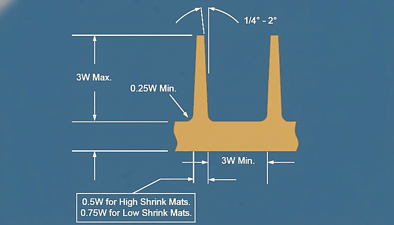
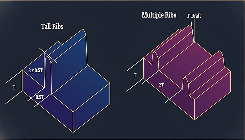
Perpendicularity failures on snap-fit hooks and latch arms occur when uneven wall thickness causes the vertical feature to lean during ejection. The base of the snap is stiffer and shrinks less; the tip cools last and contracts, pulling the hook out of perpendicular. The fix is usually a small rib behind the snap arm — a 10-minute DFM change that prevents a tolerance failure that cannot be corrected in the mold after tooling.
Tolerance Stack-Up in Assembled Plastic Subassemblies
Geometric tolerance failures rarely appear in isolation. In an assembly of three or four injection-molded parts, each with its own flatness, position, and perpendicularity variation, the worst-case stack-up can prevent proper fit even when all individual parts pass incoming inspection. This is the tolerance stack-up problem, and it is especially severe with plastic because part-to-part variation is higher than with machined metal components.
The solution is statistical tolerance analysis — RSS (root sum square) or Monte Carlo simulation — during the design phase, not after first articles fail. For assemblies with more than three molded components, statistical stack-up should be a mandatory design gate before tooling authorization. The alternative is discovering in production that a 100% yield on individual parts produces 20% assembly rejects.
Wie gibt man geometrische Toleranzen auf einer Kunststoffteil-Zeichnung an?
Start with function, not with tradition. Ask: what does this surface need to do? A sealing face needs flatness. A bearing bore needs cylindricity. A connector pin pattern needs true position. Assign only the geometric controls that the function actually requires — each additional callout adds inspection cost and creates rejection risk.
Always specify material and process conditions on the drawing. GD&T callouts for injection-molded parts should reference the measurement state: as-molded, 24-hours post-ejection, or conditioned at 23°C/50% RH per ASTM D5947. A flatness callout measured 5 minutes after ejection will read differently than one measured 24 hours later after stress relaxation — sometimes by 0.1–0.2mm on large parts.
Coordinate with your molder before finalizing the drawing. A tolerance that is technically achievable in one material may be impossible in the material your supply chain specifies. Get your molder’s DFM input on geometric callouts before the drawing reaches revision lock — changes after tooling authorization cost 10–50× more than changes in the design phase.
| GD&T-Symbol | Controls | Typical Callout Value | When to Use |
|---|---|---|---|
| Flatness ⏥ | Surface bow and twist | 0.05–0.3 mm | Sealing faces, mounting pads, parting lines |
| True Position ⊕ | Boss/hole center location | ±0.1–0.5 mm | Connector pin patterns, snap-fit locations |
| Perpendicularity ⊥ | Wall/rib/pin angle | 0.1–0.4 mm | Vertical ribs, snap arms, core pins |
| Concentricity ◎ | Bore/shaft centerline | 0.05–0.2 mm | Rotating parts, O-ring grooves |
| Parallelism ∥ | Surface-to-surface angle | 0.1–0.3 mm | Mating flanges, guide rails |
| Cylindricity ⌭ | Bore roundness + taper | 0.05–0.15 mm | Präzisionslagerbohrungen, Ventilsitze |
Nutzen Sie eine DFM-Prüfung, um geometrische Angaben gegenüber der Produktionsfähigkeit zu validieren, bevor Stahl geschnitten wird. Eine DFM-Prüfung dauert 4–8 Stunden und deckt Toleranzkonflikte auf, die sonst als Erstmusterfehler auftreten würden – zu einem Bruchteil der Kosten einer Formmodifikation.
In unserer Fabrik in Shanghai betreiben wir 47 Spritzgießmaschinen von 90T bis 1850T mit Erfahrung über 400+ Materialien. Unsere DFM-Prüfungen erkennen routinemäßig Konflikte bei geometrischen Toleranzen, bevor der Werkzeugbau beginnt – Ebenheitsangaben bei dünnwandigen Teilen, die 0,05 mm nicht halten können, oder wahre Positionsspezifikationen bei glasfasergefüllten Bossen, die 30% zusätzliche Toleranzzugabe benötigen.
Häufig gestellte Fragen
Was ist die engste geometrische Toleranz, die Spritzgießen halten kann?
Präzisions-Spritzgießen kann ±0,025–0,05 mm bei kritischen linearen Abmessungen und 0,04–0,08 mm Ebenheit mit temperaturgeregelten Werkzeugen, validierten Materialien und wissenschaftlicher Prozesskontrolle beim Spritzgießen halten. Toleranzen enger als ±0,025 mm sind mit Spritzgießen allein im Allgemeinen nicht erreichbar und erfordern sekundäre CNC-Bearbeitungsoperationen nach dem Gießen. Erreichbare geometrische Toleranz hängt stark von der Materialschrumpfrate, der geometrischen Komplexität des Teils, der Wandstärkenuniformität, dem Kühlsystemdesign und der spezifischen GD&T-Eigenschaft ab, die kontrolliert wird – Ebenheitsangaben sind typischerweise schwerer zu erreichen als wahre Position bei vielen spritzgegossenen Teilgeometrien.
Wie beeinflusst die Materialwahl geometrische Toleranzen in Kunststoffteilen?
Schrumpfungsrate und Anisotropie des Materials sind die dominierenden Faktoren für die geometrische Toleranzfähigkeit. Amorphe Harze wie ABS, PC und PMMA schrumpfen mit 0,3–0,7 % gleichmäßig in alle Richtungen und erreichen durchweg engere geometrische Toleranzen als teilkristalline Materialien. Teilkristalline Harze wie PA66, POM und PP schrumpfen mit 1–3 % und erheblicher Richtungsabhängigkeit, was Ebenheits- und Positionsangaben ohne kompensierende Formgeometrie schwerer einzuhalten macht. Glasfaserverstärkte Typen führen zu Fließrichtungsanisotropie, die ohne korrigierende Formkonstruktion und validierte Füllsimulation 0,3–0,8 mm Verzug bei 200 mm Bauteilen verursachen kann.
Was ist der Unterschied zwischen einer linearen Toleranz und einer GD&T geometrischen Toleranz?
Eine lineare Toleranz kontrolliert den Abstand zwischen zwei Punkten auf einem Teil und kann Durchbiegung, Verdrehung, Verjüngung oder Fehlausrichtung zwischen diesen Messpunkten nicht erfassen. Eine GD&T geometrische Toleranz kontrolliert die vollständige Form, Ausrichtung oder Position einer Fläche oder eines Merkmals innerhalb einer definierten Toleranzzone – sie beschränkt die gesamte Fläche, nicht nur Punkt-zu-Punkt-Abstände. Ein Teil kann bei jedem gemessenen Punkt innerhalb der ±0,1-mm-linearen Toleranz liegen und gleichzeitig eine 0,1-mm-Ebenheitsangabe verfehlen, weil die Oberfläche zwischen den Messpunkten durchbiegt, auf eine Weise, die dimensionale Prüfungen nicht erfassen können.
Kann ich GD&T wahre Position anstelle von ±XY-Koordinaten für Boss-Positionen verwenden?
Ja, und die wahre Position ist in der Regel die bessere Wahl für spritzgegossene Boss-Muster. Die wahre Position definiert eine kreisförmige Toleranzzone, die auf der nominalen Position zentriert ist, was etwas mehr Variation auf einer einzelnen Achse erlaubt, während gleichzeitig die Montagefunktion gewährleistet wird. Eine ±0,1-mm-XY-Angabe ergibt eine quadratische Zone; ein Durchmesser von 0,14 mm bei wahrer Position ergibt eine kreisförmige Zone mit äquivalenter Worst-Case-Fläche. Die wahre Position ist mit CMM-Software einfacher zu prüfen und repräsentiert die funktionalen Montageanforderungen besser, wodurch sie die bevorzugte Methode für die Positionskontrolle von Bossen und Stiften in der Produktion ist.
Warum verfehlen spritzgegossene Teile oft geometrische Toleranzen, selbst wenn die Maße im Spezifikationsbereich liegen?
Differenzielle Schrumpfung erzeugt Formfehler, die punkt-zu-punkt lineare Abmessungen völlig übersehen. Ein Bauteil kann an beiden Endpunkten exakt 100,0 mm messen, während es sich in der Mitte um 0,3 mm wölbt – innerhalb der Längentoleranz, aber eindeutig außerhalb einer Ebenheitsangabe von 0,1 mm. Druckgradienten am Anguss, ungleichmäßige Kühlung über dicke und dünne Wandzonen sowie abrupte Wanddickenübergänge erzeugen alle innere Eigenspannungen, die sich nach dem Auswerfen als geometrische Verformung und nicht als dimensionsbezogene Abweichungen an Messpunkten auswirken. Deshalb sind geometrische Kontrollen für funktionale Kunststoffbaugruppen unerlässlich.
Welche Softwarewerkzeuge helfen bei der Verwaltung geometrischer Toleranzen in gegossenen Teilen?
CAD-Pakete wie SolidWorks, Creo und CATIA enthalten eingebaute GD&T-Module, die Toleranzsymbole direkt an Merkmale im 3D-Modell anhängen. Für die Simulation sagen Moldflow und Moldex3D Schrumpfung und Verzug gegenüber Ihren GD&T-Angaben voraus, bevor Stahl geschnitten wird. Für die Prüfung wandeln Werkzeuge wie PolyWorks und Calypso CMM-Sondendaten in Abweichungskarten gegenüber Ihren geometrischen Toleranzspezifikationen um, was es einfacher macht, Toleranzüberschreitungen zu erkennen, bevor Teile versendet werden. Die Kombination von Simulation mit GD&T-bewusster Prüfung reduziert die Ablehnungsraten von Erstmustern in Produktionsumgebungen erheblich.
Bereit, Ihre spritzgegossenen Teile korrekt zu tolerieren?
Schnelle Regel: Weisen Sie Ebenheit Dichtflächen zu, wahre Position Boss-Mustern, Rechtwinkligkeit Schnappverbindungen und Zylindrizität präzisen Bohrungen. Geben Sie den Messzustand auf der Zeichnung an. Führen Sie eine Formfüllungsanalyse durch, bevor Sie Angaben für glasfasergefüllte oder teilkristalline Materialien finalisieren. Und validieren Sie Ihr Bezugsschema gegenüber Ihrer CMM-Aufspannung, bevor Erstmuster eintreffen.
Bei ZetarMold überprüft unser Engineering-Team geometrische Toleranzangaben als Teil jedes DFM-Prozesses – unrealistische Spezifikationen werden vor dem Werkzeugbau markiert, nicht danach. Wenn Sie eine Zeichnung mit GD&T-Angaben haben, bei der Sie unsicher sind, ob ein Spritzgießer sie erreichen kann, schicken Sie sie zu uns. Wir sagen Ihnen genau, was erreichbar ist und was angepasst werden muss.
Need a Quote for Your Injection Molding Project?
Get competitive pricing, DFM feedback, and production timeline from ZetarMold’s engineering team.
Kostenloses Angebot anfordern → In unserem Komplettleitfaden für Spritzgussformen finden Sie einen umfassenden Überblick.
About ZetarMold — Your Injection Molding Manufacturer
Suchen Sie einen zuverlässigen Spritzgusshersteller? ZetarMold liefert monatlich 100+ Präzisionsformen mit Expertise in 400+ Materialien. Kostenloses Angebot anfordern →
-
shrinkage: Schrumpfung: Schrumpfung bezeichnet die dimensionsbezogene Verkleinerung, die ein geformtes Bauteil beim Abkühlen und Erstarren erfährt, gemessen als Prozentsatz der ursprünglichen Formkavitätsabmessung – typischerweise 0,1 % bis 3 % abhängig von Material und Wanddicke. ↩
-
mold flow analysis: Formfüllungsanalyse: Die Formfüllungsanalyse ist eine CAE-Simulationsmethode, die vorhersagt, wie geschmolzener Kunststoff einen Formhohlraum füllt, und es Ingenieuren ermöglicht, Angusslage, Wandstärke und Kühlung vor dem Stahlschneiden zu optimieren. ↩
-
parting line: Trennlinie: Eine Trennlinie bezeichnet die Grenze an einem spritzgegossenen Teil, an der die beiden Hälften der Form aufeinandertreffen und die Trennebene definieren, die zum Auswerfen des fertigen Teils verwendet wird. ↩


