Tasarım dosyanız ±0,1 mm diyor. Kalıpçınız ±0,2 mm teklif ediyor. Müşteriniz tüm sızdırmazlık yüzeyinde 0,05 mm içinde düzlük istiyor. Birbiriyle aynı dili konuşmayan üç farklı sayı. Enjeksiyon kalıplamada toleranslandırmanın temel sorunu budur: Doğrusal ölçüler ile geometrik toleranslar aynı değildir ve bunları karıştırmak tüm üretim partisine mal olabilir.
Bu rehber, geometrik toleransların enjeksiyon kalıplamada gerçekte ne anlama geldiğini, GD&T sembollerinin kalıp ve parça gerekliliklerine nasıl dönüştüğünü ve üretimde gerçekçi olarak hangi değerleri koruyabileceğinizi belirsiz aralıklarla değil, somut rakamlarla açıklar.
- Geometrik toleranslar yalnızca boyutu değil biçimi, yönlenmeyi ve konumu da kontrol eder; bu nedenle sızdırmazlık yüzeyleri, eşleşen parçalar ve montajlar için şarttır.
- Standart enjeksiyon kalıplı parçalar ±0.1–0.2mm doğrusal toleransları korur; doğru kalıp tasarımı ve malzeme seçimiyle kritik özelliklerde ±0.05mm düzeyine ulaşılabilir.
- GD&T düzlemsellik, diklik ve gerçek konum, plastik parça çizimlerinde en sık belirtilen üç geometrik kontroldür.
- Çekme, çarpılma ve ayırma çizgisi uyumsuzluğu enjeksiyon kalıplamadaki geometrik tolerans hatalarının üç kök nedenidir.
- Kalıp ayrım çizgilerinde GD&T yassılık belirtmek, yalnızca doğrusal tolerans çağrılarına kıyasla çapak kusurlarını yaklaşık 60% azaltır.
Enjeksiyon Kalıplamada Geometrik Toleranslar Nelerdir?
Enjeksiyon kalıplamadaki geometrik toleranslar, bu bölümde açıklanan başlıca kategoriler veya seçeneklerdir. Tedarikçileri karşılaştırıyor ya da satın alma planlıyorsanız enjeksiyon kalıplama tedarikçisi bulma rehberimiz RFQ hazırlığını, yeterlilik değerlendirmesini ve ticari risk kontrollerini kapsar.
Geometrik toleranslar, bir unsurun yalnızca boyutundaki değil; biçim, yönelim, konum ve salgısındaki izin verilebilir değişimi tanımlar. Enjeksiyon kalıplamada bir parçanın çapı ±0.1mm içinde ölçülebilir ancak eşleşen yüzeyi 0.3mm düzlemsellik dışındaysa montaj yine başarısız olabilir. Bu, boyutsal değil geometrik tolerans sorunudur.
Geometrik toleransları belirtmeye yönelik resmî sistem, ASME Y14.5 ve ISO 1101 kapsamında standartlaştırılan GD&T, yani Geometrik Boyutlandırma ve Toleranslandırmadır. GD&T toleransları beş kategoriye ayırır: biçim (düzlük, doğrusallık, dairesellik, silindiriklik), yönelim (paralellik, diklik, açısallık), konum (gerçek konum, eş merkezlilik, simetri), salgı (dairesel salgı, toplam salgı) ve profil (çizgi profili, yüzey profili).
Enjeksiyonla kalıplanmış parçalarda en yaygın GD&T kontrolleri düzlemsellik (sızdırmazlık yüzeyleri, montaj yüzleri), gerçek konum (boss konumları, geçmeli kancalar) ve dikliktir (duvarlar, nervürler, pimler). Bu toleransların her biri plastiğin soğuma davranışını hesaba katmalıdır; yalnızca boyutsal bir gösterim bunu kapsayamaz.
Enjeksiyon kalıplama gerçekte hangi tolerans seviyelerini koruyabilir?
Standart ticari sınıf enjeksiyon kalıplama, kritik olmayan geometrilerde ±0.2mm tolerans sağlar. İnce toleranslı üretim, kontrollü malzemeler ve doğrulanmış kalıplarla kritik ölçülerde ±0.05–0.1mm’ye ulaşır. ±0.05mm’den daha dar toleranslar genellikle ikincil işleme veya sıcaklık kontrollü preslerle kullanılan hassas kalıplar gerektirir.
SPI (Plastik Endüstrisi Derneği) tolerans yönergeleri parçaları üç sınıfa ayırır. Ticari sınıf çoğu özellikte ±0,25 mm’ye izin verir ve tüketici ürünlerine uygundur. İnce sınıf, işlevsel bileşenlerde ±0,13 mm’yi hedefler. Hassas sınıf ise kritik özelliklerde ±0,05 mm’yi amaçlar ve tıp, havacılık ve otomotiv sızdırmazlık arayüzlerine uygulanır.
Geometrik toleranslar başka bir katman ekler. Bir ölçü şartname içinde olsa bile biçim uygun olmayabilir. 0.1mm düzlemsellik belirtilen düz bir boss yüzeyi, ±0.1mm ölçü çağrısından çok daha zordur; parçanın boyutsal konumu ne olursa olsun tüm yüzeyin 0.1mm tolerans bölgesi içinde kalmasını gerektirir.
| Tolerans Sınıfı | Doğrusal Tolerans | Düzlemsellik (GD&T) | Tipik Uygulama |
|---|---|---|---|
| Ticari | ±0.25 mm | 0.4 mm | Tüketici ürünleri, muhafazalar |
| İyi | ±0.13 mm | 0.2 mm | Mekanik montajlar, konektörler |
| Hassasiyet | ±0.05 mm | 0.08 mm | Tıbbi cihazlar, otomotiv contaları |
| Ultra hassas | ±0.025 mm | 0.04 mm | İkincil işleme gerektirir |
Malzeme seçimi, kalıp kadar tolerans kabiliyetini de belirler. PC ve ABS gibi amorf reçineler eşit biçimde küçülür ve genellikle daha sıkı toleransları korur. Naylon ve POM gibi yarı kristal malzemelerde çekme1 oranı daha yüksek ve değişkendir; bu da kalıpta telafi yapılmadan geometrik kontrollerin sağlanmasını zorlaştırır.
Plastik çekmesi geometrik toleransları nasıl etkiler?
Çekme, geometrik tolerans teorisini üretim gerçeğinden ayıran başlıca değişkendir. Her plastik malzeme eriyikten katıya geçerken — tipik olarak %0.1 ila %3 — çeker ve bu çekme karmaşık bir parçada hiçbir zaman tamamen tekdüze değildir. Tekdüze olmayan çekme, düzlük ve diklik belirtimlerini doğrudan ihlal eden çarpılma oluşturur.
Kalıp, çekmeyi telafi etmek için bilinçli olarak büyük yapılır. Nominal uzunluğu 100mm olan ve %0.5 çekme oranına sahip bir parça için 100.5mm’lik bir kalıp gözü gerekir. Ancak cidar kalınlığı değişiyorsa — örneğin bir bölgede 2mm, diğerinde 4mm — kalın kesit daha fazla ve daha geç çeker; her bölge ayrı ayrı doğrusal tolerans bandı içinde ölçülse bile parçanın düzlüğünü bozar.
Geometrik toleransların kalıp akış analizi2 gerektirmesinin nedeni budur. Akış ve soğumayı simüle etmeden farklı çekmenin nerede yoğunlaşacağını, hangi bölgelerin çarpılacağını veya çelik kesilmeden önce 0,1 mm’lik bir GD&T düzlük belirtiminin sağlanıp sağlanamayacağını öngöremezsiniz. Kalıp akış analizi, kalıp yapımı başlamadan önce geometrik tolerans gereksinimlerini tasarım kısıtlarına, yani et kalınlığı sınırlarına, yolluk konumlarına ve soğutma kanalı düzenlerine dönüştürür.
Çarpılma ve Büzülme: İki Farklı Sorun
Çekme öngörülebilir ve kalıpta telafi edilir. Çarpılma ise telafiden sonra kalan artık deformasyondur — farklı çekme, artık gerilim veya eşit olmayan soğutmadan kaynaklanır. Bir parça doğru ortalama boyutlara sahip olabilir ancak çarpılma nedeniyle 0.3mm’lik düzlemsellik toleransını yine de karşılayamayabilir. Ayrım önemlidir çünkü farklı şekilde çözülürler: çekme bir kalıp boyutu sorunudur; çarpılma ise soğutma ve ütüleme basıncı sorunudur.
Çarpılma, GD&T çiziminde tanımlanan bir referans düzlemine göre ölçülür. Parça birincil referansında sallanıyorsa sonraki her geometrik belirtim güvenilmez hâle gelir — konumsal toleranslar düz oturmayan referansları esas alır. Bu nedenle kararlı referans yüzeyleri oluşturmak, enjeksiyonla kalıplanmış montajların geometrik tolerans analizindeki ilk adımdır.
"“Ayırma line3 3 yüzeylerinde GD&T yassılık belirtmek, çapak kusurlarını doğrusal tolerans değerlerinden daha etkili biçimde azaltır.”"True
Silindiriklik ⌭
"“Daha dar doğrusal toleranslar, enjeksiyon kalıplı parçalarda GD&T geometrik kontrollerine duyulan ihtiyacı her zaman ortadan kaldırır.”"False
Doğrusal toleranslar ve geometrik toleranslar farklı değişkenleri kontrol eder. Bir parça her doğrusal boyutta ±0.05mm içinde kalmasına rağmen 0.4mm'lik düzlemsellik belirtimini karşılamayabilir; çünkü doğrusal toleranslar yüzeyin boyut aralığı içinde eğilmesine veya burulmasına izin verir. GD&T geometrik kontrolleri, doğrusal toleransların daha sıkı bir sürümü değildir; biçim, yönelim ve konumu ele alan farklı bir gereksinim kategorisidir.
Yaygın Reçinelerde Malzeme Çekmesi Karşılaştırması
Farklı malzemeler çok farklı oranlarda büzülür; bu da geometrik toleransın gerçekte ne kadar sıkı tutulabileceğini doğrudan etkiler. Aşağıda yaygın enjeksiyon kalıplama reçinelerinin tipik büzülme aralıkları ile üretimde elde edilebilen pratik düzlemsellik toleransları karşılaştırılmıştır.
ABS ve PC %0.4–0.7 oranında çeker ve üretimde 0.15–0.2mm düzlemsellikle tutarlı biçimde ±0.1mm doğrusal tolerans elde eder. Naylon 6/6 (PA66) %1.0–2.0 oranında çeker ve cam dolgulu olduğunda belirgin anizotropi gösterir; ±0.15mm doğrusal tolerans ve 0.25mm düzlemsellik elde etmek için kalıp telafisi ve dikkatli soğutma tasarımı gerekir. POM (asetal) %1.5–3.5 oranında çeker, ancak öngörülebilirdir; hassas takımla üretilen parçalarda ±0.1–0.15mm toleransa olanak tanır. PEEK ve mühendislik sınıfları %0.1–0.5 oranında çeker, ancak doğaları gereği düşük çekmeyi tutarlı biçimde elde etmek için özel takım ve proses kontrolü gerektirir.
Cam elyaf dolgulu sınıflar geometrik toleransları daha da karmaşıklaştırır. Cam elyaflar enjeksiyon sırasında akış yönünde hizalanarak anizotropik çekme oluşturur — parça, akış yönü ile akışa dik yönde farklı miktarda çeker. Bu farklı büzülme düz parçaları eğer ve boss konumlarını gerçek konum toleransının dışına kaydırır. Cam elyaf dolgulu parçalarda geometrik tolerans belirlerken %20–30 ek tolerans bırakın veya önce kalıp akış analiziyle doğrulayın.
GD&T Kalıp Tasarımına Nasıl Uygulanır?
Parça teknik resmindeki GD&T belirtimleri doğrudan kalıp çeliği gereksinimlerine dönüşür. Bir sızdırmazlık yüzeyindeki 0.05mm düzlemsellik belirtimi, kalıp kavitesinin 0.02mm’den daha iyi düzlemsellikte işlenmesi ve polisajlanması gerektiği anlamına gelir; takım aşınmasına ve proses değişimine pay bırakmak için kalıp yüzeyinin ürettiği parçadan önemli ölçüde daha hassas olması gerektiği hesaba katılır.
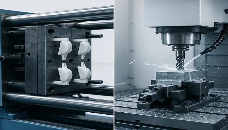
Boss ve pim konumlarındaki gerçek konum belirtimleri, kalıptaki EDM ve CNC işleme toleranslarını belirler. Bir konnektör pim düzeninde ±0.1mm gerçek konum, kalıbın maça pimi konumlarını ±0.04mm veya daha iyi bir toleransta tutmasını gerektirir; çünkü kalıplama prosesi, ütüleme basıncı ve ısıl çevrim yoluyla kendi değişkenliğini oluşturur.
Ayırma çizgisi, kalıp tasarımı ile geometrik toleranslandırmanın en doğrudan etkileştiği yerdir. Ayırma çizgisi yüzeyi düz olmalı ve iki kalıp yarısında da tam olarak eşleşmelidir. Ayırma çizgisindeki herhangi bir kademe veya boşluk çapak oluşturur ve ayrımın yakınındaki yüzeylere referans veren tüm geometrik belirtimlere yayılan bir datum hatasına yol açar. Yüksek hassasiyetli parçalarda ayırma çizgisi düzlüğü kalıpta genellikle 0,02–0,03 mm tutulur ve kalıplanmış parçada 0,04–0,07 mm sonuç verir.
Enjeksiyonla Kalıplanmış Parça Teknik Resimlerinde Datum Seçimi
Bir GD&T çiziminde seçilen datum düzeni, parçanın kalıpta, montajda ve CMM kontrol fikstüründe gerçekte nasıl sabitlendiğiyle uyumlu olmalıdır. Ayırma hattına bitişik bir datum yüzeyi seçerseniz ayırma hattı uyumsuzluğu ve çapaklar nedeniyle datum kararsızlığı yaşamanız neredeyse kesindir. En iyi uygulama: Birincil datumları ayırma yüzeylerine değil, tek bir kalıp yarısının oluşturduğu yüzeylere yerleştirin.
Enjeksiyon kalıplı parçalarda üç datum kuralı sıkı biçimde uygulanır. Datum A (birincil) en büyük ve en kararlı yüzey, genellikle göz yarısında oluşan düz taban olmalıdır. Datum B (ikincil) dönmeyi, Datum C (üçüncül) ötelemeyi kısıtlar. Teknik resimde bu hiyerarşi ihlal edildiğinde kontrol sonuçları belirsizleşir ve giriş kalite anlaşmazlıklarını çözmek neredeyse imkânsız olur.
"“Birincil datumların tek bir kalıp yarısında oluşturulan yüzeylere yerleştirilmesi, geometrik tolerans tekrarlanabilirliğini artırır.”"True
Tamamen tek bir kalıp yarısında oluşturulan yüzeyler; ayrım çizgisi hizalama değişiminden, kalıp kapama kuvvetindeki tutarsızlıktan veya ayrımdaki çapaktan etkilenmez. Bu nedenle ölçüm referansı olarak doğaları gereği daha kararlıdırlar. Datum yüzeyi her iki kalıp yarısına yayıldığında, datum konumundaki parçadan parçaya değişim sonraki tüm geometrik belirtimlere aktarılır ve görünür tolerans yığılmasını büyütür.
"“Enjeksiyonla kalıplanmış bir parçadaki herhangi bir düz yüzey, GD&T ölçümü için güvenilir bir referans görevi görebilir.”"False
Kalıplanmış parçalarda düz görünen her yüzey geometrik olarak kararlı bir datum değildir. Girişlere bitişik yüzeylerde ütüleme basıncı nedeniyle bölgesel gerilim yığılmaları oluşur. İnce cidarlara yakın yüzeyler çıkarma sırasında çarpılır. Ayırma çizgisi yüzeyleri kaçıklık basamağı hataları içerir. GD&T çiziminde yalnızca datum kararlılığı için özel olarak tasarlanmış; geniş, girişlerden uzak ve kalıbın tek yarısında oluşturulan yüzeyler birincil datum olarak tanımlanmalıdır.
Enjeksiyon Kalıplamada En Yaygın Geometrik Tolerans Hataları Nelerdir?
Enjeksiyon kalıplamada en yaygın geometrik tolerans başarısızlıkları, bu bölümde açıklanan ana kategoriler veya seçeneklerdir. Sızdırmazlık yüzeylerindeki düzlük başarısızlıkları, enjeksiyon kalıplamada geometrik tolerans redlerinin çoğunluğunu oluşturur. Kök neden neredeyse her zaman diferansiyel soğumadır — parçanın bir bölgesi daha hızlı katılaşarak yüzeyi bir kase veya eyer şekline çeker. Parçalar her noktada boyutsal şartname içinde ölçülür ancak tüm yüzey boyunca düzlük tolerans bandını karşılayamaz.
Boss ve delik düzenlerindeki gerçek konum hataları en yaygın ikinci ret nedenidir. Boss bölgesi ile çevresindeki duvar arasındaki farklı çekme, boss merkez çizgisini nominal konumundan kaydırır. Dört montaj bossuna sahip 200mm uzunluğundaki bir parçada ±0.5mm çekme farkı, dış bossları 0.3–0.5mm kaydırır; bu da kalıp işleme hatası olmasa bile ±0.2mm gerçek konum toleransını kolayca aşar.
Geçmeli kancalarda ve mandal kollarında diklik hataları, eşit olmayan duvar kalınlığı dik özelliğin çıkarma sırasında eğilmesine neden olduğunda oluşur. Geçmenin tabanı daha rijittir ve daha az büzülür; uç en son soğur ve büzülerek kancayı diklikten çıkarır. Çözüm genellikle geçme kolunun arkasındaki küçük bir federdir; takım üretiminden sonra kalıpta düzeltilemeyen tolerans hatasını önleyen 10 dakikalık DFM değişikliği.
Monte Edilmiş Plastik Alt Montajlarda Tolerans Yığılması
Geometrik tolerans hataları nadiren tek başına görülür. Her birinin kendi düzlük, konum ve diklik değişimi bulunan üç veya dört enjeksiyon kalıplı parçadan oluşan bir montajda, tüm parçalar giriş kontrolünden ayrı ayrı geçse bile en kötü durumdaki tolerans birikimi doğru oturmayı engelleyebilir. Bu, tolerans birikimi sorunudur ve parçadan parçaya değişim işlenmiş metal bileşenlere göre daha yüksek olduğundan plastiklerde özellikle ağırdır.
Çözüm, ilk numuneler başarısız olduktan sonra değil, tasarım aşamasında istatistiksel tolerans analizi — RSS (kareler toplamının karekökü) veya Monte Carlo simülasyonu — yapmaktır. Üçten fazla kalıplı bileşen içeren montajlarda istatistiksel tolerans yığılması, takım onayından önce zorunlu tasarım kapısı olmalıdır. Aksi hâlde tek tek parçalarda %100 verimin montajda %20 red oluşturduğu üretim sırasında keşfedilir.
Bir Plastik Parça Teknik Resminde Geometrik Toleranslar Nasıl Belirlenir?
Gelenekten değil işlevden başlayın. Sızdırmazlık yüzeyi düzlemsellik, yatak deliği silindiriklik, konnektör pim düzeni gerçek konum gerektirir. Yalnızca işlevin gerektirdiği geometrik kontrolleri atayın; her ek çağrı denetim maliyeti ve ret riski yaratır.
Çizimde her zaman malzeme ve proses koşullarını belirtin. Enjeksiyonla kalıplanmış parçalara yönelik GD&T gösterimleri ölçüm durumuna atıfta bulunmalıdır: kalıptan çıktığı hâli, çıkarıldıktan 24-hours sonrası veya ASTM D5947 uyarınca 23°C/50% RH koşullandırması. Çıkarıldıktan 5 dakika sonra ölçülen bir düzlemsellik değeri, gerilim gevşemesinden 24 saat sonra ölçülenden farklı çıkar; büyük parçalarda fark bazen 0.1–0.2mm olabilir.
Çizimi kesinleştirmeden önce kalıpçınızla koordinasyon kurun. Bir malzemede teknik olarak elde edilebilen bir tolerans, tedarik zincirinizin belirlediği malzemede imkânsız olabilir. Çizim revizyonu kilitlenmeden önce geometrik işaretlemeler hakkında kalıpçınızın DFM görüşünü alın; kalıp onayından sonraki değişiklikler, tasarım aşamasındaki değişikliklerden 10–50 kat daha pahalıdır.
| GD&T Sembolü | Kontroller | Tipik Belirtim Değeri | Ne Zaman Kullanılır |
|---|---|---|---|
| Düzlemsellik ⏥ | Yüzey eğilmesi ve burulması | 0.05–0.3 mm | Sızdırmazlık yüzeyleri, montaj pedleri, ayırma çizgileri |
| Gerçek Konum ⊕ | Boss/delik merkez konumu | ±0.1–0.5 mm | Konektör pin desenleri, geçmeli konumlar |
| Diklik ⊥ | Duvar/nervür/pim açısı | 0.1–0.4 mm | Dikey nervürler, geçmeli kollar, maça pimleri |
| Eş merkezlilik ◎ | Delik/mil merkez çizgisi | 0.05–0.2 mm | Dönen parçalar, O-ring kanalları |
| Paralellik ∥ | Yüzeyden yüzeye açı | 0.1–0.3 mm | Eşleşen flanşlar, kılavuz raylar |
| Silindiriklik ⌭ | Enjeksiyon Kalıplama Toleransları: Standartlar, Tablolar ve Tasarım Kılavuzları | 0.05–0.15 mm | Hassas yatak yuvaları, valf yatakları |
Çelik kesilmeden önce geometrik belirtimleri üretim kabiliyetiyle doğrulamak için DFM incelemesi kullanın. DFM incelemesi 4–8 saat sürer ve aksi halde ilk numune arızaları olarak ortaya çıkacak tolerans çelişkilerini, kalıp modifikasyonu maliyetinin çok küçük bir kısmıyla görünür kılar.
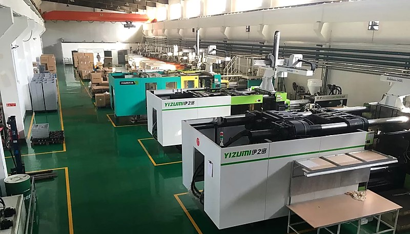
Şangay fabrikamızda 90T'den 1850T'ye kadar 47 enjeksiyon kalıplama makinesi çalıştırıyoruz ve 400'den fazla malzeme konusunda deneyimimiz var. DFM incelemelerimiz, kalıp yapımı başlamadan önce geometrik tolerans çatışmalarını rutin olarak tespit eder — 0,05 mm'yi tutamayacak ince duvarlı parçalarda düzlük belirtimleri veya 30% ek tolerans payı gerektiren cam dolgulu kaburgalarda gerçek konum spesifikasyonları.
Sıkça Sorulan Sorular
Enjeksiyon kalıplama ile tutulabilen en sıkı geometrik tolerans nedir?
Hassas enjeksiyon kalıplama; sıcaklık kontrollü takım, doğrulanmış malzemeler ve bilimsel kalıplama proses kontrolüyle kritik doğrusal ölçülerde ±0.025–0.05mm ve düzlemsellikte 0.04–0.08mm değerlerini koruyabilir. ±0.025mm’den daha sıkı toleranslar genellikle yalnızca enjeksiyon kalıplamayla elde edilemez ve kalıplamadan sonra ikincil CNC işleme operasyonları gerektirir. Elde edilebilir geometrik tolerans; malzemenin çekme oranına, parça geometrisinin karmaşıklığına, cidar kalınlığının düzgünlüğüne, soğutma sistemi tasarımına ve kontrol edilen belirli GD&T özelliğine büyük ölçüde bağlıdır. Birçok enjeksiyonla kalıplanmış parça geometrisinde düzlemsellik toleranslarını elde etmek, gerçek konum toleransından genellikle daha zordur.
Malzeme seçimi plastik parçalardaki geometrik toleransları nasıl etkiler?
Malzeme büzülme oranı ve anizotropi, geometrik tolerans kabiliyetinde baskın faktörlerdir. ABS, PC ve PMMA gibi amorf reçineler %0,3–0,7’yi tüm yönlerde düzgün bir şekilde büzülür ve yarı-kristal malzemelerden daha sıkı geometrik toleransları tutarlı bir şekelde elde eder. PA66, POM ve PP gibi yarı-kristal reçineler %1–3 büzülür ve önemli yönlü varyasyon gösterir, bu da telafi edici kalıp geometrisi olmadan düzlük ve konum belirtimlerini korumayı zorlaştırır. Cam dolgulu dereceler, düzeltici kalıp tasarımı ve doğrulanmış dolum simülasyonu olmadan 200 mm parçalarda 0,3–0,8 mm eğrilmeye neden olabilecek akış yönü anizotropisi getirir.
Doğrusal tolerans ile GD&T geometrik toleransı arasındaki fark nedir?
Doğrusal tolerans, bir parça üzerindeki iki nokta arasındaki mesafeyi kontrol eder; bu ölçüm noktaları arasındaki eğilmeyi, burulmayı, konikliği veya hizasızlığı tespit edemez. GD&T geometrik toleransı ise tanımlı bir tolerans bölgesi içinde bir yüzeyin veya unsurun tüm şeklini, yönelimini ya da konumunu kontrol eder; yalnızca noktalar arası mesafeleri değil, tüm yüzeyi sınırlar. Bir parça ölçülen her noktada ±0.1mm doğrusal tolerans içinde olabilir; ancak yüzey ölçüm noktaları arasında boyutsal kontrollerin yakalayamadığı biçimde eğildiği için aynı anda 0.1mm düzlemsellik şartını karşılamayabilir.
Boss konumları için ±XY koordinatları yerine GD&T gerçek konum toleransı kullanabilir miyim?
Evet ve gerçek konum genellikle enjeksiyonla kalıplanmış kaburga desenleri için daha iyi bir seçimdir. Gerçek konum, nominal konumda merkezlenmiş dairesel bir tolerans bölgesi tanımlar; bu, montaj fonksiyonunu garanti ederken tek bir eksende biraz daha fazla varyasyona izin verir. ±0,1 mm XY belirtimi kare bir bölge verir; 0,14 mm çapında gerçek konum ise eşdeğer en kötü durum alanına sahip dairesel bir bölge verir. Gerçek konum, CMM yazılımıyla kontrolü daha kolaydır ve fonksiyonel montaj gereksinimlerini daha iyi temsil eder; bu da onu üretim kaburgaları ve pim konum kontrolü için tercih edilen yöntem yapar.
Ölçüler tolerans içinde olsa bile enjeksiyon kalıplı parçalar neden sık sık geometrik toleransları karşılayamaz?
Diferansiyel büzülme, noktadan noktaya doğrusal boyutların tamamen kaçırdığı şekil hataları yaratır. Bir parça her iki uç noktada tam olarak 100,0 mm ölçebilirken merkezde 0,3 mm eğilebilir — uzunluk toleransı içinde ancak açıkça 0,1 mm düzlük belirtiminin dışında. Kapı basınç gradyanları, kalın ve ince duvar bölgeleri arasında dengesiz soğuma ve ani duvar kalınlığı geçişleri, hepsi ölçüm noktalarında boyutsal sapmalar olarak değil, çıkarma sonrası geometrik bozulma olarak çözülen iç kalıntı gerilmeler yaratır. Bu nedenle geometrik kontroller, fonksiyonel plastik montajlar için esastır.
Kalıplanmış parçalarda geometrik toleransları yönetmeye hangi yazılım araçları yardımcı olur?
SolidWorks, Creo ve CATIA gibi CAD paketleri, tolerans sembollerini doğrudan 3D model özelliklerine ekleyen yerleşik GD&T modülleri içerir. Simülasyonda Moldflow ve Moldex3D, çelik işlenmeden önce GD&T belirtimlerinize göre çekme ve çarpılmayı öngörür. Kontrolde PolyWorks ve Calypso gibi araçlar, CMM prob verilerini geometrik tolerans spesifikasyonlarınıza göre sapma haritalarına dönüştürerek parçalar sevk edilmeden önce tolerans dışı durumların belirlenmesini kolaylaştırır. Simülasyonu GD&T uyumlu kontrolle birleştirmek, üretim ortamlarında ilk parça ret oranlarını önemli ölçüde düşürür.
Enjeksiyon Kalıplı Parçalarınızın Toleranslarını Doğru Belirlemeye Hazır mısınız?
Hızlı kural: sızdırmazlık yüzeylerine düzlemsellik, boss desenlerine gerçek konum, geçmeli bağlantılara diklik ve hassas deliklere silindiriklik atayın. Teknik resimde ölçüm durumunu belirtin. Cam elyaf dolgulu veya yarı kristalin malzemelerde tolerans çağrılarını kesinleştirmeden önce kalıp akış analizi yapın. Ayrıca ilk numuneler gelmeden önce datum şemanızı CMM fikstürünüzle doğrulayın.
ZetarMold’da mühendislik ekibimiz her DFM sürecinde geometrik tolerans belirtimlerini inceler ve gerçekçi olmayan spesifikasyonları kalıp yapımından sonra değil önce işaretler. Bir kalıpçının karşılayıp karşılayamayacağından emin olmadığınız GD&T belirtimlerini içeren bir teknik resminiz varsa bize gönderin. Nelerin gerçekleştirilebileceğini ve nelerin düzeltilmesi gerektiğini açıkça söyleyelim.
Enjeksiyon Kalıplama Projeniz İçin Teklif mi Gerekiyor?
ZetarMold mühendislik ekibinden rekabetçi fiyat, DFM geri bildirimi ve üretim zaman çizelgesi alın.
Ücretsiz Teklif İsteyin → Kapsamlı bir genel bakış için Enjeksiyon Kalıbı Tam Kılavuzumuza bakın.
ZetarMold Hakkında — Enjeksiyon Kalıplama Üreticiniz
Güvenilir bir enjeksiyon kalıplama üreticisi mi arıyorsunuz? ZetarMold, 400+ malzemede uzmanlıkla ayda 100+ hassas kalıp teslim eder. Ücretsiz teklif isteyin →
çekme: çekme: Çekme, kalıplanmış bir parçanın soğuyup katılaşırken uğradığı boyutsal küçülmedir; özgün kalıp boşluğu ölçüsünün yüzdesi olarak ifade edilir ve malzeme ile et kalınlığına bağlı olarak genellikle %0,1 ile %3 arasındadır. ↩
kalıp akış analizi: kalıp akış analizi: Kalıp akış analizi, erimiş plastiğin bir kalıp boşluğunu nasıl dolduracağını öngörmek için kullanılan bir CAE simülasyon yöntemidir; mühendislerin çelik işlenmeden önce yolluk konumunu, et kalınlığını ve soğutmayı optimize etmesini sağlar. ↩
ayırma çizgisi: ayırma çizgisi: Ayırma çizgisi, enjeksiyonla kalıplanmış bir parçada kalıbın iki yarısının birleştiği sınırdır ve bitmiş parçayı çıkarmak için kullanılan ayrılma düzlemini tanımlar. ↩