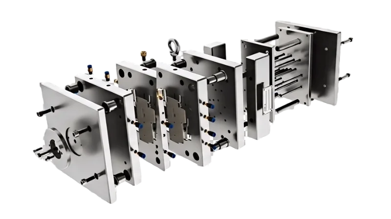
Çıkma açısı1, kalıp tasarımında yanlış belirleyebileceğiniz en önemli geometrik parametredir; ayrıca çelik işlenmeden önce fark edilirse düzeltilmesi en kolay unsurlardan biridir. Uygun çıkma açısı parçaların çizik, sürtünme izi veya deformasyon olmadan temiz biçimde çıkmasını sağlar ve çevrim süresini, kalıp ömrünü ve parça kalitesini doğrudan etkiler.
Üretimde kalıp açıları genellikle her bir tarafta 1° ila 3° arasındadır; ancak kesin değer malzemeye, yüzey kalitesine, parça geometrisine ve doku gereksinimlerine bağlıdır. Polisajlı bir PE parça yalnızca 0.5° gerektirebilirken dokulu bir naylon bileşen 3° veya daha fazlasını gerektirebilir.
Bu kılavuz kalıptan çıkma açısını belirleyen faktörleri açıklar, malzemeye özgü referans değerler sunar ve üretim sahamızdan gerçek vakaları paylaşır. İster ilk kalıbınızı tasarlıyor ister mevcut bir kalıptaki çıkarma sorunlarını gideriyor olun, aşağıdaki ilkeler doğru sonuca ulaşmanıza yardımcı olacaktır.
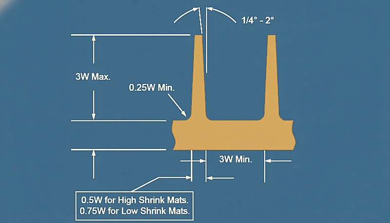 enjeksiyon kalıbı3ing çıkma açısı diyagramı" class="wp-image-53346 size-full" style="max-width:100%;height:auto;" />
"Kalıp açıları enjeksiyonda çıkarma kuvvetini azaltır."True
Uygun bir çekim açısı, parça ile kalıp arasındaki sürtünmeyi en aza indirerek fırlatmayı daha pürüzsüz hale getirir ve hasarı önler.
"Enjeksiyonla kalıplanmış tüm parçalar kalıp çıkış açısı gerektirir."False
Çoğu parça çekim açılarından yararlanırken, bazı düşük sürtünmeli malzemeler veya esnek tasarımlar sıfır veya minimum çekime izin verebilir.
Çekim Açısının Tanımı ve Önemi Nedir?
Tedarikçileri karşılaştırıyor veya satın alma planlıyorsanız enjeksiyon kalıplama tedarik kılavuzumuz; fiyat teklifi talebi hazırlığını, yeterlilik değerlendirmesini ve ticari risk kontrollerini kapsar.
Çekim açıları enjeksiyon kalıplamada çok önemlidir, parçanın düzgün bir şekilde dışarı atılmasını sağlar ve kalıbın veya nihai ürünün hasar görmesini önler.
Çekme açısı, kalıptan çıkarmaya yardımcı olmak, kusurları önlemek, fırlatma kuvvetini azaltmak ve kalıp ömrünü uzatmak için kalıplanmış parçalar üzerinde hafif bir konikliktir. Genellikle 1 ila 3 derece arasında değişir.
- Çoğu enjeksiyon parçasında 1–3° kalıp çıkış açısı standarttır; kesin değer malzemeye, dokuya ve geometriye bağlıdır.
- Yetersiz kalıp çıkış açısı parça çıkarma kusurlarına (çizikler, deformasyon) yol açarken aşırı açı boyutsal kararlılığı etkiler.
- Yüzey işlemleri (parlatma, krom kaplama) sürtünmeyi azaltır ve daha küçük draft açılarına olanak tanır.
- CAD simülasyonu ve FEA, takım yatırımından önce kalıp açılarını optimize etmeye yardımcı olur.
- Doğru draft açısı tasarımı kalıp ömrünü uzatır ve üretim maliyetlerini düşürür.
Çekim Açısının Tanımı
Çekim açısı, kalıp boşluğu veya maça ile kalıp açma yönü arasında yapılan açıdır, yani kalıp duvarının açma yönüne doğru eğimidir. Bu açı, kalıp plastik parçasının zarar görme veya deforme olma endişesi olmadan kalıptan çıkarılmasını kolaylaştırır.
Çekim Açısının Önemi
İyi tasarlanmış bir kalıp çıkış açısı, çıkarma sırasında çizilme ve deformasyon gibi kusurları önleyerek yüzey kalitesini ve hassasiyeti artırır. Doğru açı kalıp ömrünü uzatıp üretim maliyetini düşürür. Açı çok küçükse yüksek çıkarma direnci yüzeyi çizer veya parçayı deforme eder; çok büyükse boyutsal kararlılık ve kalıp ömrü etkilenir. Bu nedenle uygun çıkış açısı tasarımı üretim kalitesini ve verimliliğini artırır.
Çekim Açısı Tasarımını Etkileyen Faktörler Nelerdir?
Doğru kalıp çıkış açısı tek bir referans tablosundan elde edilmez; birbiriyle etkileşen çeşitli değişkenlerin dengelenmesiyle belirlenir. Deneyimlerimize göre aşağıdaki dört etken, kalıp çıkış açısı kararlarının 90%‘ını belirler.
Malzeme türü genellikle mühendislerin değerlendirdiği ilk faktördür; ancak yüzey finisajı, parça yapısı, kalıp hassasiyeti ve proses parametrelerinin tümü önemli rol oynar. Aşağıda her birini somut önerilerle ele alıyoruz.
Plastik Malzeme
Farklı plastikler farklı oranlarda çeker ve kalıbı farklı kuvvetlerle kavrar. Aşağıdaki tablo, yaygın enjeksiyon kalıplama malzemeleri için önerilen kalıp çıkış açısı aralıklarını özetlemektedir:
| Malzeme | Önerilen Draft Açısı | Notlar |
|---|---|---|
| Polietilen (PE) | 0.5° ila 1.5° | Düşük çekme, kaygan yüzey — minimum kalıp çıkış açısı gerekir |
| Polipropilen (PP) | 1° ila 2° | Yarı kristalin, orta düzeyde büzülme |
| Polistiren (PS) | 0.5° ila 1.5° | Amorf, düşük çekmeli, rijit |
| ABS | 1° ila 2° | Amorf, iyi kalıptan ayrılma özellikleri |
| Naylon (PA6/PA66) | 2° ila 3° | Yüksek çekme, kalıba güçlü yapışma |
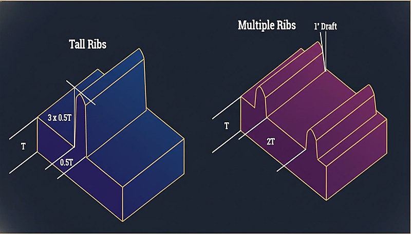
Ürün Yapısı
Çekim açısı ürünün şekli ve yapısından da etkilenir. Karmaşık şekillere ve düzensiz et kalınlığına sahip ürünlerin kolay kalıptan çıkarılması için daha büyük bir çekim açısına sahip olması gerektiği unutulmamalıdır. Örneğin, karmaşık geometrik özelliklere veya iç nervürler gibi mikro özelliklere sahip parçalar kalıptan çıkarma sırasında çok fazla direnç oluşturacaktır, bu nedenle çekim açısının artırılması gerekir.
Kalıp İşleme Hassasiyeti
Kalıp işleme hassasiyeti ne kadar yüksek ve yüzey ne kadar pürüzsüzse gereken kalıp çıkış açısı o kadar küçük olur. Buna karşılık kalıp yüzeyi pürüzlüyse çıkarma kuvvetini azaltmak için kalıp çıkış açısının artırılması gerekir. Yağlama, yüksek hassasiyetli işleme ve parlatma ile krom kaplama gibi yüzey işlemleri sürtünmeyi azaltmaya ve çıkarma verimliliğini artırmaya yardımcı olabilir.
Enjeksiyon Süreci Parametreleri
Enjeksiyon basıncı, sıcaklık ve hız gibi diğer önemli süreç parametreleri de çıkış açısı tasarımını etkiler. Daha yüksek enjeksiyon basıncı ve sıcaklık, plastik parçanın çekme oranını artırabilir ve daha büyük çıkış açısı gerektirebilir. Değişen süreç koşulları malzemenin akış ve katılaşma davranışını etkilediğinden bu unsurlar tasarım sürecinde ele alınmalıdır.
Çekim Açısı Tasarımının Temel İlkeleri Nelerdir?
Şanghay fabrikamızda tesis içi kalıp üretim birimiyle birlikte 47 enjeksiyon kalıplama makinesi (90T to 1850T) çalıştırıyoruz. Kalıp çıkış açısı sorunları karşılaştığımız en yaygın kalıp problemlerinden biridir; tasarım aşamasında doğru çözülmesi haftalarca yeniden işlemeyi ve binlerce tutarında kalıp maliyetini önler.
İyi koniklik açısı tasarımının ilkeleri basittir, ancak muhakeme gerektirir. Kalıp mühendislerimizin yeni bir kalıp planlarken izlediği kurallar şunlardır.
Temel ilke basittir: parçanın aşırı kuvvet uygulanmadan çıkmasını sağlayacak kadar koniklik ekleyin; ancak ölçüleri bozacak veya malzemeyi israf edecek kadar değil. Aşağıdaki yönergeler bu dengeyi bulmanıza yardımcı olur.
Plastik Tipine Göre Çekim Açısını Seçin
Ham sayıları tekrarlamak yerine temel mantığı düşünün: PE ve PP gibi düşük büzülmeli, kaygan malzemeler kolay çıktıkları için daha az kalıp açısı gerektirir. Naylon ve cam dolgulu bileşikler gibi yüksek büzülmeli, yapışkan malzemeler ise daha fazla açı gerektirir. İşte pratik bir karar kılavuzu:
Ürün Duvar Kalınlığını ve Şeklini Dikkate Alın
Kalın duvarlı ürünlerde büzülme ne kadar büyükse, gereken çekim açısı da o kadar büyük olur. İç dişler veya oluklar gibi karmaşık şekillere sahip ürünler de daha yüksek çekim açıları gerektirir.
Pürüzsüz Kalıp Yüzeyi Sağlayın
Kalıp yüzeyinin iyileştirilmesi kesinlikle fırlatma direncini en aza indirmeye yardımcı olacaktır, bu da kalıplama sürecinde gerekli olan çekim açısını en aza indireceği anlamına gelir. Yaygın olarak kullanılan uygulamalar parlatma ve krom kaplamadır.
Makul Enjeksiyon Süreci Parametreleri Sağlayın
Çekim açısı tasarlanırken, kalıp tasarımının enjeksiyon işlemine uygunluğunu garanti etmek için enjeksiyon işleminin gerekli parametreleri dikkate alınmalıdır. Örneğin, enjeksiyon basıncının ve sıcaklığının düşürülmesi, tasarlanan plastik parçanın büzülme oranını azaltacak ve dolayısıyla çekim açısı tasarımını geliştirecektir.
Çekim Açısı ile Kalıp Ömrü Arasındaki İlişki Nedir?
Kalıp çıkış açısı ile kalıp ömrü arasındaki ilişki, bu bölümde açıklanan işlev, kısıtlar ve ödünleşimlerle tanımlanır. Her çıkarma çevrimi kalıp yüzeyine gerilim uygular. Yeterli kalıp çıkış açısı olmadığında soğuyan plastik ile çelik kalıp boşluğu arasındaki sürtünme aşınmayı hızlandırır, takım ömrünü kısaltır ve bakım maliyetlerini artırır.
Çekim açıları, parça çıkarma sırasında sürtünmeyi azaltarak kalıp gerilimini en aza indirir ve yapışma ve hasarı önler. Uygun açılar kalıp ömrünü uzatır, verimliliği artırır ve bakım ihtiyaçlarını azaltarak ve erken kalıp arızasını önleyerek üretim maliyetlerini düşürür.
Makul bir çekim açısı sadece plastik parçaların kalitesini etkilemekle kalmaz, aynı zamanda kalıbın kullanım ömrüne de doğrudan etki eder. Çekim açısı çok küçük olduğunda, plastik parça ile kalıp arasında çok fazla sürtünme meydana gelir ve bu nedenle yüzeyi aşındırır; çekim açısı çok büyük olduğunda, ürünün boyutlarını etkileyecektir. Bu nedenle, bir taslakta gerekli olan açı tasarımları, kalıpta kullanılan malzemenin türünü, gerekli yüzey işleminin türünü ve daha uzun bir kalıp ömrü ve gelişmiş verimlilik sağlayacak diğer faktörleri içerir.
"Daha büyük kalıp çıkış açıları sürtünmeyi azaltarak kalıp ömrünü uzatır."True
Artan çekim açıları parçanın daha kolay ayrılmasını sağlayarak mekanik gerilimi azaltır ve kalıp dayanıklılığını uzatır.
"Enjeksiyon kalıplamada kalıp çıkış açıları gereksizdir."False
Çekim açıları olmadan parçalar kalıba yapışarak kusurlara, aşınmanın artmasına ve sık sık bakım yapılmasına neden olabilir, sonuçta kalıp ömrü kısalır.
Çekim Açısını Optimize Etme Yöntemleri Nelerdir?
Kalıp çıkış açısını optimize etme yöntemleri, bu bölümde açıklanan temel kategoriler veya seçeneklerdir. Modern optimizasyon; CAD analizi, simülasyon ve üretim doğrulamasının birlikte kullanılmasına dayanır. En iyi sonuç, tek bir yaklaşıma güvenmek yerine üç yöntemin birlikte uygulanmasıyla elde edilir.
Çekim açısı optimizasyonu malzeme, kalınlık ve geometriyi dikkate alarak açıları ayarlar, tipik olarak 1-3 derece. Dokulu yüzeyler daha fazlasına ihtiyaç duyar. Uygun açılar kalıp ayırmayı geliştirir, aşınmayı azaltır ve dayanıklılığı artırır.
Bilgisayar Destekli Tasarım (CAD)
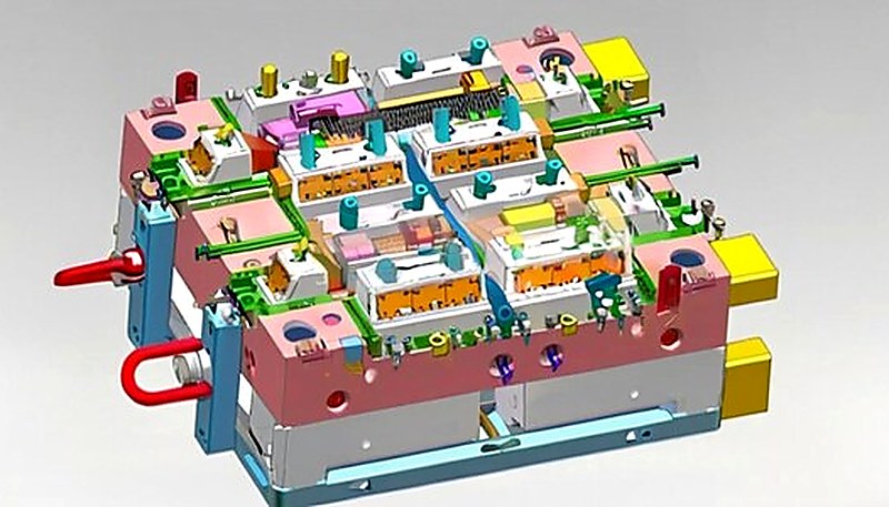
CAD yazılımı enjeksiyon kalıpları için taslak açılarını doğru bir şekilde hesaplayabilir ve simüle edebilir. İdeal açıların önceden hesaplanması ve simüle edilmesi kör tasarım olasılığını azaltabilir ve böylece tasarım verimliliğini artırabilir. Örneğin, taslak analizi için yazılım kullanıldığında, sorun olabilecek alanlar bulunabilir ve değiştirilebilir.
Sayısal Simülasyon
Deneysel Doğrulama
Gerçek üretim prosesinde açıyı kademeli olarak optimize etmek için farklı kalıp çıkış açılarının etkileri deneysel doğrulamayla karşılaştırılmalıdır. Deneyler sırasında çıkarma kuvvetini ölçmek ve ürün yüzey kalitesini gözlemlemek, çıkış açısının uygunluğunu değerlendirmeyi sağlar.
Kapsamlı Değerlendirme
Çekim açısı tasarımı sırasında malzemenin özellikleri, ürünün yapısı, kalıbın işlenmesi ve enjeksiyon işlemi parametreleri dikkate alınmalıdır, böylece tasarlanan çekim açısı ürünün kalitesini ve kalıbın dayanıklılığını koruyabilmelidir.
Enjeksiyon Kalıplarının Çekim Açısı ile İlgili Yaygın Sorunlar ve Çözümleri Nelerdir?
Enjeksiyon kalıplarındaki kalıp çıkış açısıyla ilgili yaygın sorunlar ve çözümler, bu bölümde açıklanan ana kategoriler veya seçeneklerdir. Deneyimli kalıp mühendisleri bile üretim denemeleri sırasında kalıp çıkış açısı sorunlarıyla karşılaşır. Aşağıdaki dört sorun en yaygın olanlardır ve neyse ki her biri erken fark edilirse basit bir çözüme sahiptir.
Kalıplamada dengeli bir çekim açısı, parçanın kolay ayrılmasını sağlar, bozulmayı önler, çıkarma zorluğunu en aza indirir ve kalıp aşınmasını azaltarak sorunsuz üretimi ve daha az hatayı teşvik eder.
Zor Ejeksiyon
Üretim sırasında fırlatma zorluğu yaşandığında, çekim açısı küçük olma ihtimaline karşı ölçülmelidir. Ayrılmayı optimize etmek için çekim açısı artırılmalı ve sürtünmeyi azaltmak için kalıp yüzeyi parlatılabilir veya krom kaplanabilir.
Ürün Deformasyonu
Deneyimli kalıp mühendisleri bile üretim denemeleri sırasında kalıp çıkış açısı sorunlarıyla karşılaşır. Aşağıdaki dört sorun en yaygın olanlardır — ve neyse ki erken fark edildiğinde her birinin basit bir çözümü vardır.
Yüzey Çizikleri
Yüzey çiziklerinin yaygın nedenleri arasında yetersiz kalıp açısı veya pürüzlü kalıp yüzeyi bulunur. Bu sorun, kalıp açısını artırarak ve kalıbın yüzey kalitesini iyileştirerek çözülebilir.
Aşırı Fırlatma Kuvveti
Yüksek fırlatma kuvveti, küçük çekim açısına veya enjeksiyon işlemi parametrelerinin yanlış seçimine bağlanabilir. Parçalar üzerindeki çekim açısı değiştirilerek ve enjeksiyon basıncı ve sıcaklığının düşürülmesi gibi enjeksiyon işlemi değişkenleri iyileştirilerek fırlatma kuvveti en aza indirilebilir.
"Yanlış kalıp çıkış açıları, kalıptan çıkarma sorunlarına neden olur."True
Uygun olmayan bir çekim açısı, parçaların çıkarılmasını zorlaştırarak kusurlara ve kalıpta daha fazla aşınmaya yol açabilir.
"Aşırı kalıp çıkış açıları her zaman daha iyidir."False
Aşırı çekim açıları fırlatmayı kolaylaştırsa da, parçalarda yapısal zayıflıklara ve gereksiz malzeme israfına yol açabilir.
Enjeksiyon Kalıplarının Çekim Açısının Pratik Uygulama Durumları Nelerdir?
Bu bölümde enjeksiyon kalıplarındaki çıkış açısının başlıca pratik uygulama örnekleri açıklanmaktadır. Aşağıdaki örnekler, çıkış açısı ayarlarının farklı malzemelerde ve parça geometrilerinde gerçek üretim sorunlarını nasıl çözdüğünü gösterir. Her örnek ilk tasarımı, karşılaşılan sorunu ve uygulanan düzeltici faaliyeti içerir.
Vaka 1: Polipropilen Plastik Parçalar için Çekim Açısı Tasarımı
Bir şirket, et kalınlığı 2 mm olan bir polipropilen kapak tasarlamıştır. Polipropilen için önerilen çekim açısı yaklaşık 1,5°‘dir. Üretimin ilk aşamasında, ürün çıkarıldığında kenar yüzeyinde çizikler olduğu tespit edildi. Çekim açısı 2°‘ye çıkarıldıktan sonra çizik sorunu çözüldü ve ürün yeterlilik oranı iyileştirildi.
Örnek 2: Naylon Plastik Parçalar için Çekim Açısı Tasarımı
Naylondan (PA66) üretilen bir elektronik ürün muhafazası, hem dış kozmetik yüzeye hem de iç nervür yapılarına uygun bir kalıp açısı gerektiriyordu. İlk tasarımda homojen 1.5° kalıp açısı kullanıldı, ancak numune alma sırasında iç nervürlerde sürtünme izleri görüldü. Mühendislik ekibi kalıp gözü tarafını 1.5° düzeyinde tutarken maça tarafındaki açıyı 2.5°‘ye yükseltti. Bu farklı kalıp açısı yaklaşımı sürtünme izlerini giderdi ve dış boyutsal toleransı spesifikasyon içinde tuttu.
Örnek 3: Karmaşık Şekilli Plastik Parçalar için Çekim Açısı Tasarımı
Belirli bir ev aletinin kabuğu, karmaşık bir yapıya, birçok oluğa ve nervüre sahip ABS malzemeden yapılmıştır. Çekim açısı hesaplanırken, ilk parametre olarak başlangıç çekim açısı 1,5° olarak ayarlanmıştır. Deneme üretimi sırasında, bazı oluklar fırlatmada zorluk yaşadı. Yivin çekim açısının 2,5°‘ye çıkarılması ve kalıp yüzeyinin krom kaplanmasıyla fırlatma sorunu çözüldü ve mükemmel bir ürün üretildi.
Vaka 4: Küçük Elektronik Ürün Muhafazası
Bir şirket, başlangıçta 1° çıkma açısıyla ABS malzemeden küçük bir elektronik ürün muhafazası tasarladı. Deneme üretiminde özellikle fitiller çevresinde çıkarma güçlüğü ve yüzey çizikleri görüldü. Çıkma açısı 2°‘ye yükseltildi ve kalıp yüzeyi SPI A-2 kalitesinde parlatıldı. Bu değişikliklerden sonra çıkarma kuvveti yaklaşık 40% azaldı ve yüzey kalitesi ikincil finisaj olmadan kozmetik şartnameyi karşıladı.
Vaka 5: Otomotiv Bileşenleri
Bir otomotiv parçaları üreticisinin 2,5° ilk çekim açısına sahip yüksek hassasiyetli naylon gövdeli enjeksiyon kalıplı bir parça üretmesi gerekmektedir. Küçük parti testlerinde kalıptan çıkarmanın zor olduğu ve kalıp yüzeyi aşınma oranının yüksek olduğu görülmüştür. Çekim açısının 3,5°‘ye çıkarılması ve kalıp yüzeyinin krom kaplanması kalıptan çıkarma sorununu çözmüş ve kalıp ömrünü uzatmıştır.
Vaka 6: Ev Ürünleri Plastik Parçası
Bir günlük ihtiyaç maddeleri fabrikası 3 mm et kalınlığında polipropilen plastik kaplar üretmektedir. İlk çekim açısı 1,5°‘dir. Deneme üretimi sırasında, ürün kalıptan çıkarılırken kolay deforme olur. Çekim açısı 2,5°‘ye çıkarılır, enjeksiyon prosesi parametreleri optimize edilir, kalıptan çıkarma pürüzsüz hale getirilir ve ürün kalitesi iyileştirilir.
"Kalıp çıkış açıları parçanın kalıptan çıkarılmasını iyileştirir ve kalıplama hatalarını azaltır."True
Çekim açıları sürtünmeyi azaltarak fırlatma işlemini kolaylaştırır, bu da parça hasarını ve kalıp aşınmasını en aza indirir.
"Daha yüksek kalıp çıkış açısı her zaman daha iyi sonuç verir."False
Daha büyük bir çekim açısı parçanın çıkarılmasını kolaylaştırabilirken, çok dik bir açı parçanın yapısal bütünlüğünü tehlikeye atabilir ve kalıp karmaşıklığını artırabilir.
Enjeksiyon Kalıplarının Taslak Açısının Gelecekteki Gelişim Yönü Nedir?
Enjeksiyon kalıplarındaki çıkış açısının gelecekteki gelişim yönünü bu bölümde açıklanan işlev, kısıtlamalar ve ödünleşimler belirler. İleriye bakıldığında çıkış açısı tasarımı; simülasyon yazılımlarındaki ilerlemeler, eklemeli kalıp imalatı ve yeni polimer formülasyonlarıyla birlikte gelişmektedir. Yeni nesil kalıp tasarımını üç eğilim şekillendirmektedir:
Gelecekteki enjeksiyon kalıbı taslak açıları, gelişmiş ürün kalitesi ve daha hızlı üretim için gelişmiş tasarımları kullanarak ayırma çizgisi görünürlüğünü azaltmaya, kalıp salınımını artırmaya ve atıkları en aza indirmeye odaklanmaktadır.
Günümüzde enjeksiyon kalıplama teknolojisi geliştikçe çıkma açısı tasarımı da gelişir ve en iyi yöntemleri benimser. Bilgisayar ve sayısal simülasyon teknolojileri ilerledikçe çıkma açısı tasarımı daha doğru ve daha hızlı yapılacaktır. Aynı zamanda yeni malzeme ve süreçlerin kullanılması, çıkma açısı tasarımına yeni zorluklar ve olanaklar getirecektir. Örneğin 3D baskı teknolojisindeki yenilikler, karmaşık şekilli kalıpların tasarlanması ve üretilmesi için yeni fırsatlar sunar.
"Kalıp çıkış açıları, kalıptan çıkarma sorunlarını azaltmaya yardımcı olur."True
Çekim açıları, fırlatma sırasında sürtünmeyi azaltarak kalıplanmış parçanın hasar görmesini önler ve döngü sürelerini iyileştirir.
"Çıkış açılarını artırmak kalıp verimliliğini her zaman iyileştirir."False
Çekme açıları fırlatmayı iyileştirirken, aşırı büyük açılar kalıplanan parçanın mukavemetini azaltabilir ve tasarım estetiğini etkileyebilir.
Enjeksiyon Kalıplarında Kalıp Çıkış Açısı Tasarımının Temel Sonuçları Nelerdir?
Çıkma açısı, enjeksiyon kalıbı tasarımının en kritik fakat sıkça gözden kaçırılan parametrelerinden biridir. İlk seferde doğru belirlenmesi takım düzeltme işlerini azaltır, üretim kusurlarını önler ve kalıp ömrünü uzatır; bunu üretim sahamızda her gün görüyoruz.
Başarılı bir pah açısı stratejisinin anahtarı, malzeme davranışını, yüzey kalitesi gereksinimlerini ve parça geometrisini dengelemektir. PE/PP için 1–2° ve naylon için 2–3° gibi standart aralıklar size bir başlangıç noktası verir, ancak her parça farklıdır. Bu nedenle CAD pah analizi ile üretim denemelerinin birleşimi optimizasyon için altın standart olmaya devam etmektedir. Nereden başlayacağınızdan emin değilseniz, çoğu kalıp mühendisi cilalı yüzeyler için kenar başına 1.5° ile başlamayı ve her 0.25 mm doku derinliği için 1° eklemeyi önerir.
| Karar Alanı | Doğrulanması Gerekenler |
|---|---|
| Malzeme Seçimi | Pahı reçine büzülmesiyle eşleştirin: düşük büzülmeli (PE/PP) 0.5-2°, yüksek büzülmeli (naylon/GF) 2-3° |
| Yüzey İşlemi | Parlatılmış yüzeyler daha az kalıp açısı gerektirir; her 0,25 mm doku derinliği için 1° ekleyin |
| Parça Geometrisi | Derin çekmeler, kaburgalar ve alt kesimler gerekli pah açısını artırır |
| İşlem Penceresi | Daha yüksek enjeksiyon basıncı/sıcaklığı büzülmeyi artırır — buna göre plan yapın |
Enjeksiyon Kalıplama Projeniz İçin Teklif mi Gerekiyor?
ZetarMold mühendislik ekibinden rekabetçi fiyat, DFM geri bildirimi ve üretim zaman çizelgesi alın.
Ücretsiz Fiyat Teklifi İsteyin →
Enjeksiyon Kalıplamada Kalıp Çıkış Açısı Hakkında Sık Sorulan Sorular
Enjeksiyon kalıplama için standart kalıp açısı nedir?
Çoğu enjeksiyonla kalıplanmış parça için standart kalıp açısı kenar başına 1 ila 3 derece arasındadır. PE veya PP gibi düşük büzülmeli malzemelerle parlatılmış kalıp yüzeyleri için 0,5 ila 1,5 derece yeterli olabilir. Dokulu yüzeyler tipik olarak her 0,25 mm doku derinliği için ek 1 derece kalıp açısı gerektirir. Pratikte, kenar başına 1,5 dereceyle başlayıp malzeme denemelerine dayalı olarak ayarlamak güvenilir bir yaklaşımdır. 100 mm’yi aşan çekme derinliğine sahip derin çekme parçaları için çoğu mühendis, çıkarma sırasındaki daha büyük yüzey temas alanını hesaba katmak için standart kalıp açısını 2 ila 3 dereceye çıkarır.
Pah açısı parça boyutlarını etkiler mi?
Evet, pah açısı bir parçanın kesit boyutunu üstten alta doğru doğrudan değiştirir. Kenar başına 2 derece pah açısı olan 50 mm yüksekliğindeki bir duvar için, bu duvarın üstü ile altı arasındaki fark kenar başına yaklaşık 1.75 mm’dir ve bu, duvar yüksekliğinin pah açısının tanjantının 2 katı ile çarpılmasıyla hesaplanır. Mühendisler, özellikle diğer bileşenlerle birleşen veya montajlanan parçalar için, tolerans birikimlerinde bu konikliği hesaba katmalıdır. Hassas uygulamalarda, pah kaynaklı boyutsal değişim mevcut tolerans bandının önemli bir kısmını tüketebilir, bu nedenle parça tasarımının en erken aşamalarından itibaren planlanmalıdır.
Pah olmadan enjeksiyon kalıplama yapılabilir mi?
Teknik olarak evet, ancak üretim için neredeyse hiç önerilmez. Kalıp açısı olmadan çıkarma kuvveti önemli ölçüde artarak yüzey çiziklerine, parça deformasyonuna ve hızlanmış kalıp aşınmasına neden olur. HDPE veya kauçuk benzeri TPE’ler gibi bazı esnek malzemeler, çıkarma sırasında malzeme gerildiği için sığ geometrilerde sıfıra yakın kalıp açısını tolere edebilir, ancak o zaman bile güvenilir üretim için kenar başına minimum 0,5 derece standart uygulamadır. ABS veya polikarbonat gibi rijit malzemeler için dikey yüzeylerde sıfır kalıp açılı kalıplama denemesi neredeyse her zaman sürükleme izleri ve algılanan herhangi bir tasarım faydasını aşan artan fire oranlarıyla sonuçlanır.
Yüzey dokusu kalıp açısı gereksinimlerini nasıl etkiler?
Dokulu kalıp yüzeyleri, plastik ile kalıp duvarı arasında mekanik kilitleme yaratarak çıkarma direncini önemli ölçüde artırır. Yaygın bir genel kural, her 0,25 mm doku derinliği için 1 derece kalıp açısı eklemektir. Örneğin, normalde 1 derece kalıp açısı gerektiren bir parça üzerinde 0,5 mm derinliğinde ince bir deri dokusu, artık sürükleme izleri olmadan temiz çıkarma için kenar başına en az 3 derece gerektirir. Bu, kalıp tasarım incelemelerinde en sık hafife alınan faktörlerden biridir ve tasarım aşamasında doku derinliğini hesaba katmamak genellikle ilk numune alma sonrasında maliyetli kalıp revizyonuna yol açar.
Kalıp açısı çok büyükse ne olur?
Aşırı kalıp açısı malzeme israfına neden olur, parça duvarlarını düzensiz şekilde kalınlaştırır ve çok parçalı ürünlerde montaj uyum sorunları yaratabilir. Ayrıca kullanılabilir boşluk hacmini azaltır ve artan konikliği karşılamak için eşleşen özelliklerin yeniden tasarlanmasını gerektirebilir. Aşırı durumlarda, fazla büyük bir kalıp açısı, düzensiz duvar kalınlığı dağılımı nedeniyle parçanın soğuma sırasında eğilmesine yol açabilir. Çoğu mühendis, standart parçalar için kenar başına 5 derecenin üzerindeki açıları gereksiz görür ve daha büyük açıları yalnızca derin çekme veya yoğun dokulu uygulamalar için saklar. Anahtar, parçanın işlevsel gereksinimlerinden ödün vermeden güvenilir çıkarmaya izin veren minimum kalıp açısını bulmaktır.
Kalıp açısı maça ve boşluk tarafı için aynı mıdır?
Her zaman değil. Parçanın iç yüzeyini oluşturan maça tarafı, plastik soğuma sırasında maçaya büzülerek daha fazla sürtünme ve daha yüksek çıkarma kuvveti yarattığı için çoğunlukla kavite tarafından daha fazla çıkma açısı gerektirir. Genel bir kural, maça tarafına kavite tarafına göre 0,5 ila 1 derece daha fazla açı vermektir. Bu fark özellikle derin çekimli parçalarda veya naylon ve cam elyaf dolgulu bileşikler gibi yüksek çekme oranlı malzemelerde önem kazanır. Et kalınlığı yeterli olan sığ parçalarda maça ile kavite arasındaki açı farkı ihmal edilebilir; yine de kalıp tasarım incelemesinde her zaman doğrulanmalıdır. Daha fazla bilgi için eksiksiz enjeksiyon kalıplama kılavuzumuza bakın.
çıkma açısı: Çıkma açısı, parçanın kalıptan çıkarılmasını kolaylaştırmak için dik kalıp yüzeylerine verilen eğimdir ve genellikle kalıbın açılma yönüne göre derece cinsinden ölçülür. ↩
enjeksiyon kalıplama: Enjeksiyon kalıplama, erimiş polimeri yüksek basınç altında kalıp kavitesine enjekte eden, soğutan ve katılaşmış parçayı tekrarlanabilir bir çevrimle kalıptan çıkaran üretim sürecidir. ↩
enjeksiyon kalıbı: Enjeksiyon kalıbı; enjeksiyon kalıplama çevriminde parça geometrisini, yüzey kalitesini, soğutmayı ve parçanın çıkarılma davranışını belirleyen hassas çelik takımdır. ↩