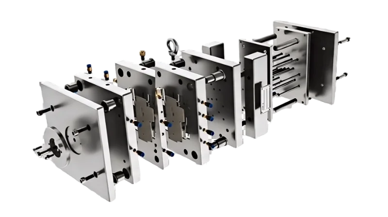
抜き勾配1は、金型設計で誤ると最も大きな問題を招く幾何学パラメータである一方、鋼材を加工する前に気付けば最も容易に修正できる項目の一つです。適切な抜き勾配により、傷、引きずり痕、変形を生じさせずに製品を円滑に離型でき、サイクルタイム、金型寿命、製品品質にも直接影響します。
生産現場では、抜き勾配は通常、片側あたり1°から3°の範囲ですが、正確な値は材料、表面仕上げ、部品形状、およびテクスチャ要件に依存します。研磨されたPE部品は0.5°のみで済む場合がある一方、テクスチャ加工されたナイロン部品では3°以上が必要となることがあります。
このガイドは抜き勾配を決定する要素を分解し、材料固有の参考値を提供し、私たちの工場現場からの実際の生産事例を共有します。初めて金型を設計する場合や既存金型の抜き問題をトラブルシューティングする場合でも、以下の原則が正しく理解するのに役立ちます。
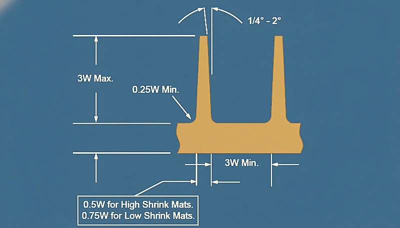 射出成形金型3成形品の抜き勾配図" class="wp-image-53346 size-full" style="max-width:100%;height:auto;" />
「抜き勾配は射出成形時の突出し力を低減します。」True
適切な抜き勾配は、部品と金型間の摩擦を最小限に抑え、排出をスムーズにし、損傷を防ぎます。
「すべての射出成形品には抜き勾配が必要である。」False
ほとんどの部品は抜き勾配の恩恵を受けますが、摩擦の少ない素材や柔軟な設計では、抜き勾配をゼロまたは最小限に抑えることができます。
ドラフト角度の定義と重要性とは?
サプライヤーを比較または調達を計画している場合は、射出成形調達ガイドでRFQの準備、適格性評価、商取引リスクの確認方法を解説しています。
抜き勾配は射出成形において不可欠であり、成形品のスムーズな突き出しを保証し、金型や最終製品の損傷を防ぎます。
抜き勾配とは、成形品にわずかなテーパーをつけることで、金型からの離型を助け、欠陥を防ぎ、突き出し力を弱め、金型の寿命を延ばすためのものです。一般的には1度から3度の範囲である。
- 1〜3°の抜き勾配はほとんどの射出成形部品の標準です;具体的な値は材料、テクスチャ、および形状に依存します。
- 抜き勾配が不足すると離型不良(キズ、変形)を引き起こし、過剰だと寸法安定性に影響します。
- 表面処理(研磨、クロメート処理)は摩擦を低減し、より小さな抜き勾配を可能にします。
- CADシミュレーションとFEAは、金型投資前に抜き勾配を最適化するのに役立ちます。
- 適切な抜き勾配設計は金型寿命を延長し、生産コストを削減します。
ドラフト角度の定義
抜き勾配とは、金型キャビティまたはコアと金型開口方向とのなす角度、すなわち金型壁の開口方向に対する傾斜のことです。この角度により、金型プラスチック部品の損傷や変形を心配することなく、脱型が容易になります。
ドラフト角度の重要性
適切に設計された抜き勾配は、抜き行程における製品の擦り傷や変形などの欠陥を回避でき、製品の表面仕上げを向上させ鋭い精度を実現します。さらに、正しい抜き勾配を得ることで金型寿命を延長し生産費用を削減できます。選択された抜き勾配が小さすぎると高い抜き抵抗が生じ、表面擦り傷やプラスチック部品の変形を引き起こします;また大きすぎると寸法安定性と金型寿命が影響を受けます。したがって、抜き勾配に関する合理的な設計は生産品質と効率を促進します。
ドラフトアングルの設計に影響を与える要因とは?
適切な抜き勾配は、単一の換算表から得られるものではありません。それは、いくつかの相互作用する変数のバランスを取った結果です。我々の経験では、以下の4つの要因が抜き勾配決定の90%を占めています。
材料タイプは通常エンジニアが最初に考慮する要素ですが、表面仕上げ、部品構造、金型精度、およびプロセスパラメータも重要な役割を果たします。以下ではそれぞれについて具体的な推奨事項を説明します。
プラスチック素材
異なるプラスチックは収縮率や金型への抱き力が異なります。下表は一般的な射出成形材料に対する推奨抜き勾配範囲をまとめています:
| 素材 | 推奨抜き勾配 | 備考 |
|---|---|---|
| ポリエチレン(PE) | 0.5° ~ 1.5° | 低収縮、滑りやすい — 最小限の抜き勾配が必要 |
| ポリプロピレン(PP) | 1°から2° | 半結晶性、中程度の収縮 |
| ポリスチレン(PS) | 0.5° ~ 1.5° | 非晶質、低収縮、剛性 |
| ABS | 1°から2° | 非晶質、離脱性良好 |
| ナイロン(PA6/PA66) | 2° ~ 3° | 高収縮、金型への強い粘着 |
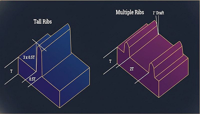
製品構造
抜き勾配は製品の形状や構造にも影響される。複雑な形状の製品や肉厚が不均一な製品は、離型しやすくするために抜き勾配を大きくする必要がある。例えば、複雑な形状の部品や内部リブのような微細な形状の部品は、脱型時に大きな抵抗が発生するため、抜き勾配を大きくする必要がある。
金型加工精度
金型加工精度が高く表面が平滑であるほど、必要な抜き勾配は小さくなります。逆に、金型表面が粗い場合、抜き力を減らすために抜き勾配を増加させる必要があります。潤滑、高精度加工、および研磨やクロメート処理などの表面処理は、摩擦を減らし抜き効率を向上させるのに役立ちます。
射出プロセスパラメーター
射出圧力、温度、速度などの他の重要なプロセスパラメータも抜き勾配設計に影響します。高い射出圧力と温度はプラスチック部品の収縮率を増加させる効果があり、より大きな抜き勾配を要求する可能性があります。変化するプロセス条件は材料の流動と固化における挙動に影響を与えるため、これらの要素は設計プロセスで考慮される必要があります。
ドラフトアングル設計の基本原則とは?
上海工場では、47台の射出成形機(90Tから1850T)と社内金型製造設備を運営しています。抜き勾配の問題は私たちが遭遇する最も一般的な工具問題の一つであり、設計段階から正しく設定することで、数週間の再作業と数千ドルの工具コストを節約できます。
良い抜き勾配設計の背後にある原則は単純ですが、判断が必要です。新しい金型を計画する際に、私たちの工具エンジニアが従うガイドラインは以下の通りです。
基本原則は単純です:過度な力なしで部品が離型できる十分なテーパーを付けるが、寸法を損なったり材料を無駄にしたりしない程度に留めることです。以下のガイドラインはそのバランスを見つけるのに役立ちます。
プラスチックの種類に応じてドラフト角度を選択
単なる数値の羅列ではなく、根本的な理屈を考えましょう:PEやPPのような低収縮で滑りやすい材料は、離型が容易なため、抜き勾配を小さくできます。ナイロンやガラス充填材のような高収縮で粘着性のある材料は、より大きな抜き勾配が必要です。以下に実践的な判断ガイドを示します:
製品の肉厚と形状を考慮する
肉厚製品の収縮率が大きいほど、ドラフト角は大きくなる。また、内ねじや溝など複雑な形状の製品では、抜き勾配を大きくする必要があります。
滑らかな金型表面の確保
金型表面の仕上げを向上させることは、射出抵抗を最小にすることに間違いなく役立ち、成形工程で必要とされる抜き勾配を最小にすることを意味する。一般的には、研磨とクロムメッキが使用されます。
合理的な射出プロセスパラメータの確保
抜き勾配を設計する場合、射出工程に適合した金型設計を保証するために、射出工程の必要なパラメータを考慮しなければなりません。例えば、射出圧力と射出温度を下げると、設計されたプラスチック部品の収縮率が減少し、その結果、抜き勾配設計が向上します。
ドラフト角度と金型寿命の関係は?
抜き勾配と金型寿命の関係は、このセクションで説明される関数、制約条件、トレードオフによって定義されます。各抜き行程は金型表面にストレスを与えます。適切な抜き勾配がない場合、冷却中のプラスチックと鋼製キャビティ間の摩擦が摩耗を加速し、工具寿命を短縮し、維持コストを増加させます。
抜き勾配は、部品排出時の摩擦を減らし、金型へのストレスを最小限に抑え、固着や損傷を防ぎます。適切な角度は、金型寿命を延ばし、効率を向上させ、メンテナンスの必要性を減らし、金型の早期故障を防ぐことで生産コストを削減します。
適度な抜き勾配はプラスチック部品の品質に影響するだけでなく、金型の寿命にも直接影響します。抜き勾配が小さすぎると、プラスチック部品と金型との摩擦が大きくなり、表面が摩耗してしまいます。このように、抜き勾配に要求される角度設計は、金型に使用される材料の種類、要求される表面処理の種類など、金型の寿命を延ばし、効率を向上させるための要素を特徴としています。
「抜き勾配を大きくすると、摩擦が減り、金型寿命が延びる。」True
抜き勾配を大きくすることで、部品の離型が容易になり、機械的ストレスが軽減され、金型の耐久性が長くなります。
"射出成形に抜き勾配は不要である。"False
抜き勾配がないと、部品が金型に固着し、欠陥の原因となり、摩耗が進み、メンテナンスが頻繁になり、最終的に金型寿命が短くなる。
ドラフト角度を最適化する方法とは?
抜き勾配を最適化する手法は、このセクションで説明される主要なカテゴリーまたは選択肢です。現代的な抜き勾配の最適化は、CAD解析、シミュレーション、生産検証の組み合わせに依存しています。単一のアプローチに頼るよりも、これら3つの手法を併用することで最良の結果が得られます。
ドラフト角度の最適化は、材料、厚さ、形状を考慮して角度を調整する。テクスチャー面ではさらに必要です。適切な角度は、離型性を高め、摩耗を減らし、耐久性を向上させます。
コンピューター支援設計(CAD)
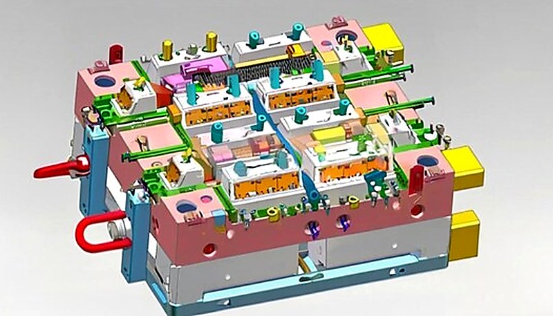
CADソフトウェアは、射出成形金型の抜き勾配を正確に計算し、シミュレーションすることができます。理想的な角度を事前に計算し、シミュレーションすることで、設計の盲点を減らし、設計効率を向上させることができます。例えば、抜き勾配解析ソフトを使えば、問題がありそうな箇所を発見し、修正することができます。
数値シミュレーション
実験的検証
実際の生産プロセスでは、異なる抜き勾配の効果を実験的に確認して比較し、角度を徐々に最適化する必要があります。実験の過程で、抜き出し力を測定し、製品表面品質を観察することで、抜き勾配の合理性を評価できます。
総合的な検討
抜き勾配の設計では、材料の特性、製品の構造、金型の加工方法、射出工程のパラメータを考慮し、設計された抜き勾配が製品の品質と金型の耐久性を損なわないようにする必要があります。
射出成形金型の抜き勾配に関する一般的な問題と解決策とは?
射出金型の抜き勾配に関する一般的な問題と解決策は、このセクションで説明される主なカテゴリーまたは選択肢です。経験豊富な金型エンジニアでも、生産試作時に抜き勾配の問題に直面することがあります。以下の4つの問題は最も一般的であり、幸い早期に発見すればそれぞれに簡単な解決策があります。
バランスの取れた抜き勾配は、成形品の離型を容易にし、歪みを防止し、排出の困難を最小限に抑え、金型の摩耗を減少させ、スムーズな生産と不良品の減少を促進する。
難排出
生産中に排出が困難になった場合、抜き勾配が小さい可能性があるため、抜き勾配を測定する必要があります。分離を最適化するためには、抜き勾配を大きくし、金型表面を研磨するかクロームメッキを施して摩擦を減少させる。
製品の変形
経験豊富な金型エンジニアでも、生産試作時に抜き勾配の問題に直面することがあります。以下の4つの問題は最も一般的であり、幸い早期に発見すればそれぞれに簡単な解決策があります。
表面の傷
表面キズの一般的な原因には、抜き勾配の不足や金型表面の粗さが含まれます。この問題は、抜き勾配の角度を上げ、金型の表面品質を向上させることで解決できます。
過剰な排出力
高い射出力は、小さな抜き勾配と射出プロセスパラメータの不適切な選択に起因している可能性があります。部品の抜き勾配を修正し、射出圧力や射出温度を下げるなどの射出プロセス変数を改善することにより、射出力を最小限に抑えることができます。
「抜き勾配が不適切だと、離型不良が発生する。」True
抜き勾配の角度が不適切な場合、部品の突き出しが困難になり、欠陥の発生や金型の摩耗の増加につながります。
「抜き勾配は大きければ大きいほどよい。」False
過度の抜き勾配は排出を容易にするかもしれないが、部品の構造的弱点や不必要な材料の浪費につながる可能性がある。
射出成形金型の抜き勾配の実用例は?
射出金型の抜き勾配の実践適用事例は、このセクションで説明される主なカテゴリーまたは選択肢です。以下の実践事例は、抜き勾配調整が異なる材料や部品形状における実際の生産問題をどのように解決したかを示しています。各事例には初期設計、遭遇した問題、および実施された修正措置が含まれます。
事例1:ポリプロピレン樹脂部品の抜き勾配設計
ある会社が肉厚2mmのポリプロピレン製キャップを設計した。ポリプロピレンの推奨抜き勾配は約1.5°である。製造の初期段階で、製品を排出する際に端面に傷がつくことが判明した。ドラフト角度を2°にしたところ、傷の問題は解決され、製品の認定率も向上した。
事例2:ナイロン樹脂部品の抜き勾配設計
ナイロン(PA66)製の電子製品筐体では、外部の外観面と内部リブ構造両方に対応できる抜き勾配が必要でした。初期設計では均一な1.5°の抜き勾配を使用しましたが、サンプリング時に内部リブに引き跡が現れました。エンジニアリングチームはコア側の抜き勾配を2.5°に増加させ、キャビティ側を1.5°に維持しました。この差動抜き勾配アプローチにより引き跡が解消され、外部寸法公差は仕様内に維持されました。
事例3:複雑な形状のプラスチック部品の抜き勾配設計
ある家電製品のシェルはABS素材でできており、複雑な構造で、多くの溝やリブがある。抜き勾配を計算する際、最初のパラメータとして抜き勾配を1.5°に設定する。試作中、一部の溝は排出が困難でした。溝の抜き勾配を2.5°にし、金型表面にクロムメッキを施すことで、突き出しの問題を解決し、完璧な製品を生産することができた。
ケース4:小型電子製品の筐体
ある企業がABS材料を用いて小型電子製品のハウジングを設計した際、初期の抜き勾配は1°でした。試作段階で、特にリブ部周辺で離型困難や表面キズが観察されました。抜き勾配を2°に増やし、金型表面をSPI A-2仕上げに研磨したところ、離型力は約40%低下し、表面品質は二次仕上げなしで化粧仕様を満たしました。
ケース5:自動車部品
ある自動車部品メーカーは、抜き勾配2.5°の高精度ナイロンボディ射出成形品を製造する必要があった。小ロットでのテストでは、離型が難しく、金型表面の摩耗率が高いことがわかりました。抜き勾配を3.5°にし、金型表面にクロムメッキを施すと、脱型の問題は解決し、金型寿命も延びた。
ケース6:家庭用製品のプラスチック部品
ある日用品工場では、肉厚3mmのポリプロピレン製プラスチック容器を生産している。初期の抜き勾配は1.5°。試作中、脱型時に製品が変形しやすい。抜き勾配を2.5°にすると、射出工程パラメータが最適化され、脱型がスムーズになり、製品の品質が向上した。
「抜き勾配は成形品の突出しを改善し、成形不良を低減する。」True
抜き勾配は、摩擦を減らすことで排出プロセスを容易にし、部品の損傷や金型の摩耗を最小限に抑えます。
「抜き勾配は大きいほど、常に良い結果が得られる。」False
抜き勾配を大きくすれば、部品の取り外しが容易になるが、角度が急すぎると、部品の構造的完全性が損なわれ、金型の複雑さが増す可能性がある。
射出成形金型の抜き勾配の今後の発展方向は?
射出成形金型の抜き勾配の将来の発展方向は、このセクションで説明された機能、制約、トレードオフによって定義されます。将来を見据えると、抜き勾配設計は、シミュレーションソフトウェアの進歩、工具製造のための付加製造、新しいポリマー配合とともに進化しています。3つのトレンドが次世代の金型設計を形作っています:
将来の射出成形用金型の抜き勾配は、パーティングラインの視認性の低減、離型性の向上、廃棄物の最小化に重点を置き、製品品質の向上と生産の迅速化のために高度な設計を活用する。
射出成形技術の進歩に伴い、抜き勾配の設計も改善され、より優れた手法が採用されます。コンピューター技術と数値シミュレーション技術の発展により、抜き勾配はさらに正確かつ迅速に設計できるようになります。同時に、新材料や新工程の適用は、抜き勾配設計に新たな課題と可能性をもたらします。例えば、3Dプリント技術の革新により、複雑形状の金型を設計・製作する新たな機会が生まれています。
"抜き勾配は、金型からの離型不良を抑えるのに役立ちます。"True
抜き勾配は射出時の摩擦を減らし、成形品の損傷を防ぎ、サイクルタイムを向上させます。
「抜き勾配を大きくすれば、必ず金型効率が向上する。」False
抜き勾配は射出性を向上させますが、過度に大きな勾配は成形品の強度を低下させ、意匠性にも影響します。
射出成形金型における抜き勾配設計の重要な要点は何ですか?
抜き勾配は、射出成形金型設計で最も重要でありながら見落とされがちなパラメータの一つです。最初から適切に設定すれば、金型の手直しを減らし、量産不良を防ぎ、金型寿命を延ばせます。当社の生産現場でも、その効果を日々確認しています。
成功する抜き勾配戦略の鍵は、材料の挙動、表面仕上げ要件、部品形状のバランスを取ることです。PE/PPでは1〜2°、ナイロンでは2〜3°などの標準範囲は出発点となりますが、すべての部品は異なります。そのため、CADによる抜き勾配解析と生産試験を組み合わせた最適化がゴールドスタンダードとなっています。どこから始めればよいかわからない場合は、ほとんどの工具設計エンジニアが、研磨面では側面あたり1.5°から始め、テクスチャー深さ0.25 mmごとに1°追加することを推奨しています。
| 意思決定エリア | 部品がまだ初期検証段階にある場合は、本格的な生産前に少量射出成形に対応できるかどうかをサプライヤーに確認してください。この選択肢は、大規模な生産に投資する前に、テスト用のパイロット部品、市場からのフィードバック、段階的な承認が必要な場合のリスクを軽減します。 |
|---|---|
| 素材の選択 | 樹脂の収縮率に合わせた抜き勾配:低収縮(PE/PP)0.5-2°、高収縮(ナイロン/GF)2-3° |
| 表面仕上げ | 研磨面は抜き勾配が少なくて済む;テクスチャー深さ0.25 mmごとに1°追加 |
| 部品形状 | 深絞り、リブ、アンダーカットはすべて必要な抜き勾配を増加させます |
| プロセスウィンドウ | 高い射出圧力/温度は収縮を増加させます — それに応じて計画してください |
射出成形プロジェクトのお見積もりが必要ですか?
ZetarMoldのエンジニアリングチームから、競争力のある価格、DFMフィードバック、量産スケジュールを入手してください。
無料見積りを依頼 →
射出成形における抜き勾配に関するよくある質問
射出成形における標準的な抜き勾配は何ですか?
ほとんどの射出成形部品の標準的な抜き勾配は、側面あたり1〜3度の範囲です。PEやPPなどの低収縮材料を使用した研磨された金型表面では、0.5〜1.5度で十分な場合があります。テクスチャー加工された表面では、通常、テクスチャーの深さ0.25 mmごとに追加で1度の抜き勾配が必要です。実際には、側面あたり1.5度から始め、材料試験に基づいて調整するのが信頼性の高いアプローチです。引き出し深さが100 mmを超える深絞り部品の場合、ほとんどのエンジニアは、射出時の接触面積の増加を考慮して、標準的な抜き勾配を2〜3度に増やします。
抜き勾配は部品の寸法に影響しますか?
はい、抜き勾配は部品の上面から下面までの断面寸法を直接変化させます。高さ50mmの壁で片側2度の抜き勾配がある場合、その壁の上面と下面の差は片側約1.75mmになります(抜き勾配の正接の2倍×壁高で計算)。エンジニアは、特に他の部品と組み合わさったり組み立てられたりする部品において、公差累積計算でこのテーパーを考慮しなければなりません。精密用途では、抜き勾配によって生じる寸法変動が利用可能な公差帯のかなりの部分を消費する可能性があるため、部品設計の初期段階から計画する必要があります。
抜き勾配なしで射出成形できますか?
技術的には可能ですが、生産ではほとんど推奨されません。抜き勾配がないと、射出力が劇的に増加し、表面キズ、部品変形、金型摩耗の加速を引き起こします。HDPEやゴムのようなTPEなどの柔軟な材料では、浅い形状の場合、射出時に材料が伸びるため、ほぼゼロの抜き勾配に耐えられることがありますが、それでも確実な生産のためには側面あたり最低0.5度が標準的な慣行です。ABSやポリカーボネートなどの剛性材料では、垂直面でのゼロ抜き勾配成形は、ドラグマークの発生や不良率の増加をほぼ確実に引き起こし、設計上の利点を上回るデメリットをもたらします。
表面テクスチャーは抜き勾配要件にどのように影響しますか?
テクスチャー加工された金型表面は、プラスチックと金型壁の間に機械的なインターロックを生み出し、取り出し抵抗を大幅に増加させます。一般的な経験則として、テクスチャー深さ0.25mmごとに抜き勾配を1度追加します。例えば、通常1度の抜き勾配が必要な部品に0.5mmの深さの細かいレザーグレインテクスチャーを施す場合、引っかき傷なしにきれいに取り出すには、少なくとも片側3度以上の勾配が必要です。これは金型設計レビューで最も頻繁に過小評価される要因の一つであり、設計段階でテクスチャー深さを考慮しないと、初期サンプリング後にコストのかかる金型修正が必要になることがよくあります。
抜き勾配が大きすぎるとどうなりますか?
過剰な抜き勾配は材料を無駄にし、部品の肉厚を不均一に厚くし、複数部品製品では組み立て適合性の問題を引き起こす可能性があります。また、使用可能なキャビティ容積を減少させ、増加したテーパーに対応するために嵌合部の再設計が必要になる場合もあります。極端な場合、過大な抜き勾配は肉厚分布の不均一により冷却中の部品の反りを引き起こす可能性があります。ほとんどのエンジニアは、標準部品では側面あたり5度を超えるものは不要と考え、より大きな角度は深絞りまたは高度なテクスチャー加工が施された用途にのみ使用します。鍵は、部品の機能要件を損なうことなく確実な取り出しを可能にする最小限の抜き勾配を見つけることです。
コア側とキャビティ側の抜き勾配は同じですか?
必ずしも同じではありません。製品内面を形成するコア側は、冷却時にプラスチックがコアへ収縮して摩擦と突出し力が大きくなるため、キャビティ側より大きな抜き勾配を必要とすることがよくあります。一般的な目安は、コア側をキャビティ側より0.5~1度大きくすることです。この差は、深絞り形状の製品や、ナイロン、ガラス繊維強化材のように収縮率が高い材料で特に重要です。浅い製品で肉厚に余裕がある場合は差が無視できることもありますが、必ず金型設計レビューで確認してください。詳しくは射出成形完全ガイドをご覧ください。