

Tolerâncias geométricas — os limites que controlam a forma, orientação, localização e batimento das características numa peça moldada por injeção — são a diferença entre um componente que se encaixa perfeitamente e um que acaba no contentor de sucata. Ao contrário das simples tolerâncias dimensionais de mais/menos, o dimensionamento e toleranciamento geométrico (GD&T) usa uma linguagem simbólica padronizada definida na ASME Y14.51 e ISO 11012 para comunicar a intenção de projeto de forma inequívoca. Se está a especificar peças plásticas para aplicações automóveis, médicas ou de eletrónica de consumo, compreender as tolerâncias geométricas não é opcional — é uma competência fundamental de engenharia.
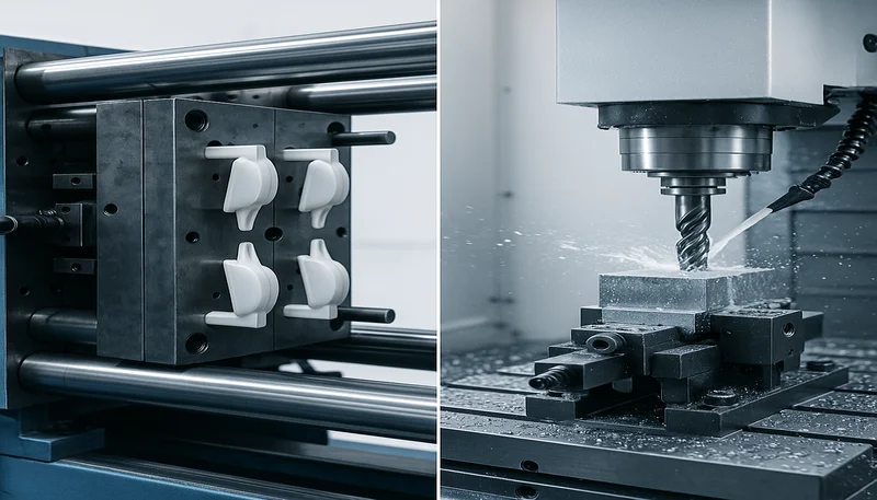
Na nossa fábrica em Xangai, operamos 47 máquinas de moldagem por injeção de 90T a 1850T, produzindo peças com controlos geométricos apertados para clientes em todo o mundo. Com mais de 20 anos de experiência com mais de 400 materiais plásticos, testemunhámos em primeira mão como uma especificação adequada de GD&T evita disputas dispendiosas entre projetistas, fabricantes de moldes e equipas de qualidade. Este guia decompõe os principais tipos de tolerância geométrica que precisa de conhecer para a moldagem por injeção, explica quais são mais importantes para peças plásticas e partilha dicas práticas do chão de fábrica.
- A GD&T utiliza símbolos padronizados (ASME Y14.5 / ISO 1101) para definir forma, orientação, localização e batimento.
- A planaridade e a retilineidade são as tolerâncias geométricas mais críticas para as peças moldadas por injeção.
- O encolhimento e o empeno do material tornam as tolerâncias geométricas mais difíceis de manter do que no usinagem de metal.
- A seleção do datum deve refletir a montagem funcional — não apenas a conveniência de usinagem.
- Especificar excessivamente tolerâncias geométricas aumenta os custos de ferramentas e inspeção sem agregar valor.
O que são tolerâncias geométricas e porque são importantes na moldagem por injeção?
Tolerâncias geométricas e por que são importantes na moldagem por injeção são as principais categorias ou opções explicadas nesta secção. As tolerâncias geométricas são os limites da variação admissível na forma, orientação e posição de uma peça, para além do que apenas as dimensões lineares conseguem capturar. Um furo pode ter o diâmetro correto mas estar fora de posição; uma superfície pode ter a espessura correta mas estar demasiado empenada para vedar. O GD&T aborda estas realidades com 14 tipos de tolerâncias organizadas em cinco categorias: forma, orientação, localização, batimento e perfil.
Em moldagem por injeção, as tolerâncias geométricas são especialmente importantes porque as peças de plástico sofrem encolhimento, empeno e tensões internas durante o arrefecimento. Uma peça que parece perfeita no momento da ejeção pode distorcer-se nas próximas 24 a 48 horas à medida que as tensões residuais relaxam. Isto significa que a tolerância geométrica que especifica deve ter em conta não apenas o processo de moldagem em si, mas também a alteração dimensional pós-moldagem. Por exemplo, uma especificação de planaridade de 0,1 mm numa caixa de policarbonato de 150 mm pode exigir um design especial da entrada, uma pressão de manutenção otimizada e potencialmente um dispositivo para restringir a peça durante o arrefecimento.
A norma ASME Y14.5 define a linguagem simbólica completa para GD&T nos Estados Unidos, enquanto a ISO 1101 desempenha o mesmo papel internacionalmente. Ambas as normas utilizam um quadro de controlo de características — uma caixa retangular que contém o símbolo da característica geométrica, o valor da tolerância e quaisquer referências de datum. Compreender como ler e aplicar estes quadros é a base para comunicar os requisitos de tolerância ao seu fornecedor de moldes por injeção.
Quais símbolos de GD&T são mais relevantes para peças moldadas por injeção de plástico?
Nem todos os 14 símbolos de GD&T são igualmente relevantes para a moldagem por injeção. Na prática, um punhado de tolerâncias geométricas representa a grande maioria das indicações em desenhos de peças plásticas. Aqui está uma análise hierarquizada dos símbolos mais frequentemente utilizados e porque são importantes para componentes moldados.
| Símbolo GD&T | Category | Aplicação típica | Dificuldade de manutenção |
|---|---|---|---|
| Planaridade | Forma | Superfícies de vedação, faces de montagem | Alto (empeno) |
| Retilineidade | Forma | Nervuras, bordos, características cilíndricas | Médio |
| Circularidade | Forma | Bosses cilíndricos, furos | Médio |
| Perpendicularidade | Orientação | Boss para face, parede para flange | Médio-Alto |
| Paralelismo | Orientação | Paredes opostas, características de encaixe por pressão | Elevado |
| Posição | Localização | Padrões de furos, pontos de montagem | Médio |
| Concentricidade | Localização | Características rotativas, assentos de rolamento | Muito elevado |
| Perfil de uma superfície | Perfil | Superfícies curvas complexas | Elevado |
A planicidade é, sem dúvida, a tolerância geométrica mais importante para peças moldadas por injeção. Uma superfície de vedação que se encurve apenas 0,15 mm pode ter fugas. Uma face de montagem que empena 0,2 mm pode causar desalinhamento na montagem. Na nossa experiência, os problemas de planicidade representam aproximadamente 30-40% de todas as não-conformidades geométricas em peças moldadas. As causas principais são geralmente arrefecimento desigual, colocação inadequada do gate, ou retração do material que não foi devidamente simulada durante o projeto do molde.
A tolerância de posição é a seguinte mais crítica. Quando tem uma matriz de furos de montagem ou presilhas de encaixe, a sua localização relativa determina se a montagem se junta. A tolerância de posição é muitas vezes mais útil do que as tolerâncias coordenadas individuais porque permite uma tolerância bónus a partir do tamanho real da característica — algo particularmente valioso com peças de plástico onde os diâmetros dos furos podem variar devido ao encolhimento.
Como é que a escolha do material afeta a tolerância geométrica na moldagem por injeção?
O material que seleciona tem um impacto direto e frequentemente dramático nas tolerâncias geométricas que pode realisticamente manter. Materiais amorfos como policarbonato (PC) e ABS tendem a encolher mais uniformemente e a manter melhor a planaridade do que materiais semicristalinos como nylon (PA6, PA66) ou POM, que sofrem um encolhimento significativo impulsionado pela cristalização. Os compostos com carga de vidro complicam ainda mais as coisas porque a orientação das fibras cria um encolhimento anisotrópico — a peça encolhe de forma diferente ao longo da direção do fluxo versus perpendicularmente a ele.

Consider a practical example: a 200 mm x 150 mm flat cover in PA66-GF30 (30% glass-filled nylon 66). The mold flow simulation3 might predict 0.6% shrinkage in the flow direction and 0.3% transverse — a 2:1 ratio. If you specify flatness of 0.1 mm, you are likely asking for something the material simply cannot deliver without extraordinary measures like in-mold fixtures or post-mold annealing. A more realistic flatness callout for this scenario would be 0.3-0.5 mm.
This is where an experienced injection mold supplier adds real value. With 8 senior engineers and experience across 400+ materials, we help customers understand what geometric tolerances are achievable for their specific material, part geometry, and production volume. Specifying tolerances that are physically impossible to hold does not improve quality — it only increases scrap rate and cost.
“GD&T can specify tolerances that account for material shrinkage after molding.”Verdadeiro
By combining GD&T with mold flow simulation data, designers can predict post-shrinkage geometry and specify tolerances that reflect the part’s final equilibrium state, not just its as-molded condition.
“Tighter geometric tolerances always produce better parts.”Falso
Over-tolerancing increases tooling cost, inspection time, and scrap rate without improving functional performance. The right tolerance is the loosest one that still satisfies assembly and function requirements.
Que Normas Regulam as Tolerâncias Geométricas para Peças de Plástico Moldadas?
Geometric tolerancing standards are primarily governed by two frameworks worldwide: ASME Y14.5 and ISO 1101. ASME Y14.5 dominates in North America, while ISO 1101 (with companion standards ISO 5458 and ISO 5459) is used in Europe and Asia. Both standards define the same fundamental concepts but differ in some notation details and default rules.
For injection molded parts specifically, ISO 20457:2018 provides additional guidance on dimensional tolerances for molded parts, including a classification system that accounts for mold-related factors like part geometry, gate location, and material behavior. This standard recognizes that plastic parts have fundamentally different tolerance capability than machined metal parts, and that applying machining-grade GD&T to molded plastics is economically unrealistic.
When preparing drawings for injection molding quotes, always specify which standard you are using. A tolerance frame interpreted under ASME Y14.5 may yield different results than the same frame under ISO 1101, particularly for position tolerances and datum usage. Misalignment on standards interpretation is one of the most common sources of quality disputes between buyers and molders.
Como Especificar Tolerâncias Geométricas nos Desenhos de Peças Moldadas por Injeção?
Three elements are needed to specify geometric tolerances: the tolerance type, the tolerance value, and the datum reference frame. The datum reference frame is arguably the most important — and most frequently misapplied — element. Datums define the reference surfaces from which all other measurements are taken. For injection molded parts, datum selection must consider how the part will be inspected, not just how it functions.
A common mistake is using the parting line as a datum. The parting line is the interface between the mold halves, and while it seems like a stable reference, it can flash, shift, or wear over the life of the mold. A better approach is to designate functional features — such as a flat mounting boss or a precision-bored hole — as datums. These features are directly machined into the mold steel and maintain their geometric integrity over hundreds of thousands of cycles.
Here is a practical specification workflow: First, identify the features that must mate with other components. Second, assign datums to the most stable and accessible of these features. Third, apply the loosest geometric tolerance that still guarantees function. Fourth, validate your callouts with your fornecedor de moldagem por injeção before finalizing the drawing — they can tell you what is realistically achievable given the part geometry, material, and production constraints.
O Que Causa Desvios de Tolerância Geométrica Durante a Moldagem por Injeção?
Warpage, uneven cooling, ejection forces, and mold wear are the primary causes of geometric tolerance deviations during injection molding. Understanding these causes helps you set realistic tolerances and design more dimensionally stable parts.
Warpage is the number-one enemy of geometric tolerance in injection molding. It occurs when different regions of the part cool and shrink at different rates. Thin sections cool faster than thick sections. Areas near the gate receive more packing pressure than areas far from the gate. Fiber-filled materials develop internal stresses from oriented fibers that release as the part equilibrates. The result is a part that was geometrically correct in the mold but distorted when measured 24 hours later.

Ejection forces are another significant factor. As the part cools, it shrinks onto the mold core. The ejector pins must push the part off, and this force can temporarily distort thin walls or delicate features. Well-designed ejector systems distribute force evenly, but even optimal ejection can introduce sub-tenth-millimeter geometric deviations on critical surfaces.
Mold wear and maintenance also play a role. After 100,000+ cycles, mold surfaces can erode, especially around gate areas and sliding cores. This gradual wear shifts dimensions and can cause geometric features to drift out of tolerance. Regular mold maintenance and periodic first-article inspections are essential to catch this drift before it affects production quality.
“Mold flow simulation can predict geometric tolerance outcomes before steel is cut.”Verdadeiro
Modern mold flow simulation tools like Moldflow and Moldex3D can predict warpage, shrinkage, and fiber orientation with sufficient accuracy to validate geometric tolerance feasibility during the design phase.
“Post-mold annealing always improves geometric tolerance compliance.”Falso
Annealing relieves internal stresses but can also cause additional distortion if not carefully controlled. For some materials and geometries, annealing actually worsens flatness or position accuracy. It must be evaluated case by case.
Como Pode Otimizar o Design da Peça para uma Melhor Conformidade com Tolerâncias Geométricas?
Uniform wall thickness, proper rib proportions, and strategic gate placement are the key design strategies for geometric tolerance compliance. These strategies improve dimensional stability without increasing cost.
Uniform wall thickness is the single most impactful design decision for geometric control. When wall thickness varies significantly across a part, thick sections shrink more than thin sections, creating internal stresses that cause warpage. A wall thickness variation greater than 15-20% in a crystalline material is almost guaranteed to produce geometric non-conformance on flat surfaces. Where thickness transitions are unavoidable, use gradual ramps instead of sharp steps to distribute stress more evenly.
Rib design also affects geometric outcomes. Ribs add stiffness, which helps maintain flatness — but they also create localized thick sections that shrink more than the surrounding wall. Keep rib thickness at 50-60% of the nominal wall thickness for most materials, and avoid intersecting ribs that create thick nodes. Corrugated wall sections can provide equivalent stiffness with better geometric stability than traditional ribs.
Gate location and type deserve careful consideration. The gate is where molten plastic enters the cavity, and its location determines the flow pattern, weld-line placement, and packing pressure distribution — all of which affect the final geometry. A single edge gate creates a unidirectional flow that favors parallelism along the flow direction. Multiple gates can balance filling but introduce weld lines that create weak points and geometric discontinuities.
ZetarMold’s quality team includes 10+ QC specialists who follow a 6-step inspection workflow covering IQC, in-process checks, and final OQC to verify geometric tolerance compliance on every production run.
Como Medir e Inspecionar Tolerâncias Geométricas em Peças Moldadas?
CMMs, optical scanners, and functional gauges are the three primary methods for measuring geometric tolerances on injection molded plastic parts. Each method has specific advantages depending on the tolerance type and production volume.
CMM measurement with touch probes is the standard for position, perpendicularity, and parallelism checks. However, plastic parts are compliant — probe contact force can deflect the surface, introducing measurement error. Using low-probe-force CMMs (typically under 50 mN) or non-contact laser probes minimizes this issue. For flatness measurement, optical scanning with structured light provides full-surface data rather than the sparse point sets from touch probes, giving a more accurate picture of the actual surface condition.
Functional gauging remains the most practical method for high-volume production. A go/no-go gauge that simulates the mating component provides a pass/fail result that directly correlates with assembly function. While gauges cannot tell you exactly how much geometric deviation exists, they are fast, repeatable, and require minimal operator skill — making them ideal for in-process inspection on the production floor.
Quais são as faixas realistas de tolerância geométrica para peças moldadas por injeção?
Geometric tolerance ranges for injection molded parts are typically between 0 and 1 mm, depending on tolerance type, material, and part geometry. The following table provides practical ranges based on industry experience and standard tolerance references for injection molding.
| Tolerance Type | Precision (Tight) | Standard (Normal) | Coarse (Loose) |
|---|---|---|---|
| Flatness (per 100 mm) | 0.05–0.10 mm | 0.10–0.30 mm | 0.30–0.60 mm |
| Straightness (per 100 mm) | 0.05–0.10 mm | 0.10–0.25 mm | 0.25–0.50 mm |
| Circularity (diameter) | 0.03–0.08 mm | 0.08–0.15 mm | 0.15–0.30 mm |
| Perpendicularity (per 100 mm) | 0.05–0.10 mm | 0.10–0.25 mm | 0.25–0.50 mm |
| Parallelism (per 100 mm) | 0.08–0.15 mm | 0.15–0.35 mm | 0.35–0.70 mm |
| Position (RFS) | Ø0.10–0.20 mm | Ø0.20–0.50 mm | Ø0.50–1.00 mm |
| Perfil de uma superfície | 0.10–0.20 mm | 0.20–0.50 mm | 0.50–1.00 mm |
These ranges assume standard processing conditions with optimized conceção do molde. Achieving the ‘Precision’ column typically requires specialized tooling features like conformal cooling, in-mold pressure sensors, and possibly post-mold fixturing. The ‘Standard’ column represents what a well-designed mold running on a modern injection molding machine can consistently produce. The ‘Coarse’ column is appropriate for non-critical aesthetic or structural features.
“Conformal cooling channels in the mold can improve flatness by up to 40%.”Verdadeiro
Conformal cooling channels follow the part contour, providing more uniform cooling that reduces thermal gradients and the resulting warpage. Studies show flatness improvements of 30-50% compared to conventional drilled channels.
“Glass-filled materials always improve dimensional stability and geometric tolerance.”Falso
Glass fibers improve stiffness and reduce overall shrinkage, but they introduce anisotropic shrinkage that can worsen warpage and flatness. The fiber orientation depends on flow direction, so parallelism and flatness may actually degrade in certain orientations.
Porque deve discutir os requisitos de tolerância geométrica com o seu fornecedor de moldagem antecipadamente?
The biggest geometric tolerance problems we see in our factory are not caused by bad molding — they are caused by bad specification. Designers who finalize tolerances without consulting their injection mold supplier often specify tolerances that are either unrealistically tight or poorly targeted at non-critical features. Both mistakes waste money.
Early collaboration between the design team and the molding supplier enables several critical optimizations. First, the supplier can run mold flow simulations to validate whether the specified tolerances are achievable for the given geometry and material. Second, the tooling team can optimize gate location, cooling layout, and ejection strategy to target the most critical geometric features. Third, the quality team can design inspection protocols and fixtures that focus measurement effort on the features that matter most for function.
With our in-house mold manufacturing facility supporting 100+ mold sets per month, we can iterate on tool design quickly to achieve the best possible geometric tolerance outcomes. Our ISO 9001, ISO 13485, ISO 14001, and ISO 45001 certified quality systems ensure that geometric tolerance requirements are maintained throughout production, from first article to millionth part.
Precisa de Peças Moldadas por Injeção de Precisão com Tolerâncias Geométricas Apertadas?
ZetarMold is a Shanghai-based manufacturer delivering precision injection molded parts with tight geometric tolerances and 20+ years of experience. Our 8 senior engineers work with you from the design stage to optimize part geometry, material selection, and tool design for the best dimensional outcomes. Whether you need flat sealing surfaces within 0.1 mm or position tolerances for precision mounting holes, our team has the expertise and equipment to deliver. Get a free quote today and let us help you specify and achieve the right geometric tolerances for your project.
Perguntas Frequentes sobre Tolerâncias Geométricas na Moldagem por Injeção
Perguntas mais frequentes
What is the difference between dimensional tolerances and geometric tolerances?
Dimensional tolerances control the allowable variation in a single linear measurement such as a length, width, or diameter expressed as a plus or minus range. Geometric tolerances by contrast control the shape orientation or spatial relationship of a feature: how flat a surface is how perpendicular two faces are or how accurately a hole is positioned relative to a datum. For injection molded parts geometric tolerances are often more critical than dimensional ones because they directly determine whether components fit together and function properly in assembly. In practice most part drawings need both types to fully communicate design intent.
Can injection molding achieve the same geometric tolerances as CNC machining?
Generally no. CNC machining can routinely hold geometric tolerances of 0.01-0.05 mm because the cutting tool directly creates the geometry with minimal material behavior variability. Injection molding involves material shrinkage warpage and process variability that make tolerances below 0.05 mm impractical for most part geometries and materials. However injection molding is far more economical for high-volume production even with slightly looser tolerances. The key is to design parts that function reliably with the geometric tolerance range that molding can consistently deliver rather than forcing molding to match machining capabilities.
How does part size affect achievable geometric tolerance?
Larger parts are harder to hold to tight geometric tolerances because shrinkage accumulates over greater distances and uneven cooling becomes more pronounced. A flatness of 0.1 mm over 50 mm is achievable for most engineering plastics but the same 0.1 mm over 300 mm is extremely difficult in semi-crystalline materials. Tolerance specifications should scale with feature size often expressed as a percentage or per-unit-length value. A practical guideline is to expect flatness capability of approximately 0.1 to 0.2 percent of the feature length for amorphous materials and 0.2 to 0.4 percent for semi-crystalline materials.
What is the most common geometric tolerance mistake on plastic part drawings?
The most common mistake is over-tolerancing: specifying geometric tolerances that are tighter than functional requirements demand. This drives up tooling cost increases scrap rate and slows inspection throughput without any benefit to the end product. The second most common mistake is incorrect datum selection where the chosen datum features are not stable accessible or functionally relevant for measurement. Both mistakes often stem from applying metal-machining tolerance practices to plastic parts without accounting for the fundamental differences in how molded parts behave dimensionally during and after production.
Does using a higher-pressure injection molding machine improve geometric tolerances?
Higher injection pressure alone does not improve geometric accuracy. Packing pressure must be carefully optimized for each part and material combination. Too little pressure causes short shots and sink marks while too much pressure causes flash over-packing and internal stresses that lead to warpage and dimensional instability. Process optimization through scientific molding principles including decoupled filling and packing stages with pressure and temperature sensors is far more effective than simply increasing machine tonnage or injection pressure without a systematic approach.
How soon after molding should you measure geometric tolerances?
For most engineering plastics you should wait at least 24 hours after molding before taking critical geometric measurements. Some semi-crystalline materials like nylon and PEEK continue to dimensionally stabilize for up to 48-72 hours due to ongoing post-crystallization and stress relaxation. Amorphous materials like polycarbonate and ABS stabilize faster but still benefit from a minimum 12 to 24 hour equilibration period. Measuring too early gives misleading results that do not reflect the part final geometry and can lead to incorrect process adjustments that actually worsen quality outcomes.
Can you use GD&T on 3D-printed injection molds for prototyping?
3D-printed molds such as those made with SLA resin or metal powder bed fusion can produce prototype parts for form and fit testing. However the geometric tolerance capability is significantly looser than production steel molds because printed molds have lower thermal conductivity less precise cavity surfaces and limited pressure resistance. Expect tolerances 3 to 5 times wider than what a hardened tool steel mold can achieve. GD&T callouts on prototype parts should be clearly marked as preliminary and re-evaluated when transitioning to production tooling made from hardened steel.
What role does mold temperature play in geometric tolerance control?
Mold temperature directly affects cooling rate crystallization behavior and residual stress formation all of which influence the final geometric accuracy of the molded part. Higher mold temperatures produce more uniform cooling and lower internal stresses which typically improves flatness and warpage control. However higher mold temperature also increases cycle time and production cost. For semi-crystalline materials mold temperature also affects the degree of crystallization which in turn affects shrinkage magnitude. Finding the optimal mold temperature is a balance between geometric quality production efficiency and cost considerations.
-
ASME Y14.5: ASME Y14.5 refers to the American national standard for geometric dimensioning and tolerancing, published by the American Society of Mechanical Engineers. ↩
-
ISO 1101: ISO 1101 refers to the international standard for geometrical product specifications (GPS) — geometrical tolerancing — tolerances of form, orientation, location and run-out. ↩
-
mold flow simulation: mold flow simulation refers to computational analysis of the injection molding process that predicts fill pattern, pressure distribution, and warpage before mold fabrication. ↩


