Las tolerancias geométricas (los límites que controlan la forma, la orientación, la ubicación y el descentramiento de las características en una pieza moldeada por inyección) son la diferencia entre un componente que encaja perfectamente y uno que termina en el contenedor de chatarra. A diferencia de las tolerancias dimensionales más/menos simples, las tolerancias y dimensionamiento geométrico (GD&T) utilizan un lenguaje simbólico estandarizado definido en ASME Y14.51 e ISO 11012 para comunicar la intención del diseño sin ambigüedades. Si especifica piezas de plástico para aplicaciones automotrices, médicas o de electrónica de consumo, comprender las tolerancias geométricas no es opcional: es una habilidad básica de ingeniería.
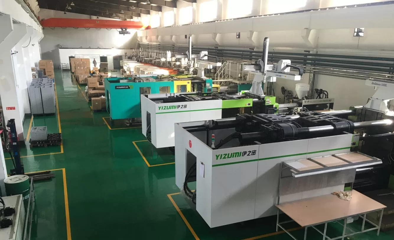
En nuestra fábrica de Shanghai operamos 47 máquinas de moldeo por inyección de 90T a 1850T y fabricamos piezas con estrictos controles geométricos para clientes de todo el mundo. Con más de 20 años de experiencia y más de 400 materiales plásticos, hemos comprobado de primera mano cómo una especificación GD&T adecuada evita costosas disputas entre diseñadores, fabricantes de moldes y equipos de calidad. Esta guía explica los principales tipos de tolerancias geométricas que debe conocer para el moldeo por inyección, cuáles son más importantes para las piezas de plástico y consejos prácticos procedentes del taller de producción.
- GD&T utiliza símbolos normalizados (ASME Y14.5 / ISO 1101) para definir forma, orientación, ubicación y oscilación.
- La planicidad y la rectitud son las tolerancias geométricas más críticas para las piezas moldeadas por inyección.
- La contracción del material y el alabeo hacen que las tolerancias geométricas sean más difíciles de mantener que en el mecanizado de metales.
- La selección del datum debe reflejar el ensamblaje funcional, no solo la conveniencia del mecanizado.
- Sobreespecificar las tolerancias geométricas aumenta los costos de herramienta e inspección sin agregar valor.
¿Qué son las tolerancias geométricas y por qué son importantes en el moldeo por inyección?
Las tolerancias geométricas y por qué son importantes en el moldeo por inyección son las principales categorías u opciones explicadas en esta sección. Las tolerancias geométricas son los límites de la variación admisible en la forma, orientación y posición de una pieza que las dimensiones lineales por sí solas no pueden expresar. Un orificio puede tener el diámetro correcto y aun así estar fuera de posición; una superficie puede medir el espesor correcto y estar demasiado alabeada para sellar. GD&T aborda estas realidades con 14 tipos de tolerancia organizados en cinco categorías: forma, orientación, ubicación, oscilación y perfil.
En el moldeo por inyección, las tolerancias geométricas son especialmente importantes porque las piezas de plástico sufren contracción, deformación y tensiones internas durante el enfriamiento. Una pieza que parece perfecta en el momento de la expulsión puede distorsionarse durante las siguientes 24 a 48 horas a medida que se relajan las tensiones residuales. Esto significa que la tolerancia geométrica que especifique debe tener en cuenta no sólo el proceso de moldeo en sí, sino también el cambio dimensional posterior al moldeo. Por ejemplo, una indicación de planitud de 0,1 mm en una carcasa de policarbonato de 150 mm puede requerir un diseño de compuerta especial, una presión de retención optimizada y potencialmente un accesorio para restringir la pieza durante el enfriamiento.
La norma ASME Y14.5 define el lenguaje simbólico completo de GD&T en Estados Unidos, mientras que ISO 1101 desempeña la misma función a escala internacional. Ambas normas utilizan un marco de control de características: un recuadro rectangular que contiene el símbolo de la característica geométrica, el valor de tolerancia y cualquier referencia a datums. Comprender cómo leer y aplicar estos marcos es la base para comunicar los requisitos de tolerancia a su proveedor de moldes de inyección.
¿Qué símbolos GD&T son más relevantes para las piezas de plástico moldeadas por inyección?
No todos los 14 símbolos de GD&T son igual de relevantes para el moldeo por inyección. En la práctica, unas pocas tolerancias geométricas representan la gran mayoría de las indicaciones en los planos de piezas de plástico. A continuación se presenta una clasificación de los símbolos más utilizados y se explica por qué son importantes para los componentes moldeados.
| Símbolo de GD&T | Categoría | Aplicación típica | Dificultad de mantener |
|---|---|---|---|
| Planicidad | Forma | Superficies de sellado, caras de montaje | Alto (alabeo) |
| Rectitud | Forma | Costillas, bordes, características cilíndricas | Medio |
| Circularidad | Forma | Bosses cilíndricos, agujeros | Medio |
| Perpendicularidad | Orientación | Refuerzo a cara, pared a brida | Medio-Alto |
| Paralelismo | Orientación | Paredes opuestas, características de ajuste a presión | Alta |
| Posición | Ubicación | Patrones de agujeros, puntos de montaje | Medio |
| Concentricidad | Ubicación | Características giratorias, asientos de rodamientos | Muy alta |
| Perfil de una superficie | Perfil | Superficies curvas complejas | Alta |
La planicidad es posiblemente la tolerancia geométrica más importante para las piezas moldeadas por inyección. Una superficie de sellado que se arquea incluso 0,15 mm puede tener fugas. Una cara de montaje que se deforma 0,2 mm puede causar desalineación en el ensamblaje. En nuestra experiencia, los problemas de planicidad representan aproximadamente el 30-40% de todas las no conformidades geométricas en piezas moldeadas. Las causas principales suelen ser un enfriamiento desigual, una ubicación inadecuada de la compuerta o una contracción del material que no se simuló correctamente durante el diseño del molde.
La tolerancia de posición es la siguiente más crítica. En una matriz de orificios de montaje o clips de encaje a presión, su ubicación relativa determina si el conjunto puede montarse. La tolerancia de posición suele ser más útil que las tolerancias de coordenadas individuales porque permite una tolerancia adicional derivada del tamaño real de la característica, algo especialmente valioso en piezas de plástico cuyos diámetros de orificio pueden variar por contracción.
¿Cómo afecta la elección del material la tolerancia geométrica en el moldeo por inyección?
El material que seleccionas tiene un impacto directo y a menudo dramático en las tolerancias geométricas que puedes mantener de manera realista. Los materiales amorfos como el policarbonato (PC) y el ABS tienden a contraerse de manera más uniforme y mantienen una mejor planitud que los materiales semicristalinos como el nailon (PA6, PA66) o el POM, que experimentan una contracción significativa impulsada por la cristalización. Los compuestos con fibra de vidrio complican aún más las cosas porque la orientación de las fibras crea una contracción anisotrópica: la pieza se contrae de manera diferente a lo largo de la dirección del flujo en comparación con la perpendicular.
Consideremos un ejemplo práctico: una cubierta plana de 200 mm x 150 mm en PA66-GF30 (30% nailon 66 relleno de vidrio). La simulación del flujo del molde3 podría predecir una contracción del 0,6 % en la dirección del flujo y del 0,3 % transversal, una proporción de 2:1. Si especifica una planitud de 0,1 mm, probablemente esté pidiendo algo que el material simplemente no puede ofrecer sin medidas extraordinarias como fijaciones en el molde o recocido post-molde. Una indicación de planitud más realista para este escenario sería 0,3-0,5 mm.
Aquí es donde un proveedor experimentado de moldes de inyección aporta un valor real. Con 8 ingenieros sénior y experiencia con 400+ materiales, ayudamos a los clientes a comprender qué tolerancias geométricas pueden conseguirse con su material, geometría de pieza y volumen de producción específicos. Especificar tolerancias que son físicamente imposibles de mantener no mejora la calidad: solo aumenta la tasa de desecho y el coste.
"GD&T permite especificar tolerancias que tengan en cuenta la contracción del material después del moldeo."True
Al combinar GD&T con datos de simulación del flujo del molde, los diseñadores pueden predecir la geometría posterior a la contracción y especificar tolerancias que reflejen el estado de equilibrio final de la pieza, no solo su condición recién moldeada.
"Unas tolerancias geométricas más estrictas siempre producen piezas mejores."False
Especificar tolerancias excesivas aumenta el coste del utillaje, el tiempo de inspección y la tasa de rechazo sin mejorar el rendimiento funcional. La tolerancia correcta es la más amplia que aún satisface los requisitos de montaje y funcionamiento.
¿Qué normas rigen las tolerancias geométricas para piezas plásticas moldeadas?
Las normas de tolerancias geométricas se rigen principalmente por dos marcos en todo el mundo: ASME Y14.5 e ISO 1101. ASME Y14.5 predomina en Norteamérica, mientras que ISO 1101 (junto con las normas complementarias ISO 5458 e ISO 5459) se utiliza en Europa y Asia. Ambas normas definen los mismos conceptos fundamentales, pero difieren en algunos detalles de notación y reglas predeterminadas.
Para las piezas moldeadas por inyección, ISO 20457:2018 ofrece orientación adicional sobre tolerancias dimensionales, incluido un sistema de clasificación que considera factores relacionados con el molde, como la geometría de la pieza, la ubicación de la compuerta y el comportamiento del material. Esta norma reconoce que las piezas de plástico tienen una capacidad de tolerancia fundamentalmente distinta a la de las piezas metálicas mecanizadas y que aplicar GD&T propio del mecanizado a los plásticos moldeados no es económicamente realista.
Al preparar planos para solicitar presupuestos de moldeo por inyección, especifique siempre qué norma utiliza. Un marco de tolerancia interpretado según ASME Y14.5 puede producir resultados distintos al mismo marco interpretado según ISO 1101, especialmente en las tolerancias de posición y el uso de referencias. Las diferencias en la interpretación de las normas son una de las fuentes más frecuentes de disputas de calidad entre compradores y moldeadores.
¿Cómo Se Especifican las Tolerancias Geométricas en los Planos de Piezas Moldeadas por Inyección?
Para especificar tolerancias geométricas se necesitan tres elementos: el tipo de tolerancia, su valor y el sistema de referencia de datums. Este último es posiblemente el elemento más importante y el que más se aplica de forma incorrecta. Los datums definen las superficies de referencia desde las que se toman las demás mediciones. En piezas moldeadas por inyección, su selección debe considerar cómo se inspeccionará la pieza, no solo cómo funciona.
Un error habitual es utilizar la línea de partición como datum. La línea de partición es la interfaz entre las mitades del molde y, aunque parece una referencia estable, puede presentar rebaba, desplazarse o desgastarse durante la vida útil del molde. Un enfoque mejor consiste en designar características funcionales —como un resalte de montaje plano o un orificio mandrinado con precisión— como datums. Estas características se mecanizan directamente en el acero del molde y mantienen su integridad geométrica durante cientos de miles de ciclos.
A continuación se muestra un flujo de trabajo de especificación práctico: Primero, identifique las características que deben coincidir con otros componentes. En segundo lugar, asigne datos de referencia a las funciones más estables y accesibles. En tercer lugar, aplique la tolerancia geométrica más flexible que aún garantice el funcionamiento. En cuarto lugar, valide sus llamadas con su proveedor de moldeo por inyección antes de finalizar el dibujo; ellos pueden decirle qué se puede lograr de manera realista dadas las limitaciones de geometría, material y producción de la pieza.
¿Qué Causa Desviaciones de Tolerancia Geométrica Durante el Moldeo por Inyección?
El alabeo, la refrigeración desigual, las fuerzas de expulsión y el desgaste del molde son las principales causas de desviaciones de las tolerancias geométricas durante el moldeo por inyección. Comprender estas causas ayuda a establecer tolerancias realistas y diseñar piezas con mayor estabilidad dimensional.
El alabeo es el principal enemigo de la tolerancia geométrica en el moldeo por inyección. Se produce cuando distintas zonas de la pieza se enfrían y contraen a velocidades diferentes. Las secciones delgadas se enfrían más rápido que las gruesas. Las zonas próximas al punto de inyección reciben más presión de compactación que las alejadas. Los materiales reforzados con fibras desarrollan tensiones internas por la orientación de estas, que se liberan cuando la pieza se equilibra. El resultado es una pieza geométricamente correcta dentro del molde, pero deformada al medirla 24 horas después.
Las fuerzas de expulsión son otro factor importante. Al enfriarse, la pieza se contrae sobre el núcleo del molde. Los pasadores expulsores deben separarla, y esta fuerza puede deformar temporalmente las paredes delgadas o las características delicadas. Los sistemas de expulsión bien diseñados distribuyen la fuerza uniformemente, pero incluso una expulsión óptima puede introducir desviaciones geométricas inferiores a una décima de milímetro en superficies críticas.
El desgaste y el mantenimiento del molde también influyen. Tras 100,000+ ciclos, las superficies del molde pueden erosionarse, especialmente alrededor de las zonas de entrada y los núcleos deslizantes. Este desgaste gradual altera las dimensiones y puede hacer que las características geométricas queden fuera de tolerancia. El mantenimiento regular del molde y las inspecciones periódicas del primer artículo son esenciales para detectar esta desviación antes de que afecte a la calidad de producción.
"La simulación del flujo del molde puede predecir los resultados de tolerancia geométrica antes de cortar el acero."True
Las herramientas modernas de simulación del flujo del molde, como Moldflow y Moldex3D, pueden predecir la deformación, la contracción y la orientación de las fibras con precisión suficiente para validar la viabilidad de las tolerancias geométricas durante la fase de diseño.
"El recocido posterior al moldeo siempre mejora el cumplimiento de las tolerancias geométricas."False
El recocido alivia las tensiones internas, pero también puede causar deformaciones adicionales si no se controla cuidadosamente. En algunos materiales y geometrías, el recocido empeora la planitud o la precisión de posición. Debe evaluarse caso por caso.
¿Cómo Puedes Optimizar el Diseño de la Pieza para un Mejor Cumplimiento de las Tolerancias Geométricas?
Un espesor de pared uniforme, unas proporciones adecuadas de las nervaduras y una ubicación estratégica de los puntos de inyección son las principales estrategias de diseño para cumplir las tolerancias geométricas. Estas estrategias mejoran la estabilidad dimensional sin aumentar el coste.
Un espesor de pared uniforme es la decisión de diseño que más influye en el control geométrico. Cuando el espesor de pared varía considerablemente dentro de una pieza, las secciones gruesas se contraen más que las delgadas y generan tensiones internas que provocan alabeo. Una variación del espesor de pared superior al 15-20% en un material cristalino casi garantiza una falta de conformidad geométrica en superficies planas. Cuando las transiciones de espesor sean inevitables, utilice rampas graduales en lugar de escalones abruptos para distribuir la tensión de forma más uniforme.
El diseño de las nervaduras también afecta a los resultados geométricos. Las nervaduras aportan rigidez, lo que ayuda a mantener la planitud, pero también crean secciones gruesas localizadas que se contraen más que la pared circundante. Mantenga el espesor de las nervaduras en el 50-60% del espesor nominal de pared para la mayoría de los materiales y evite las intersecciones de nervaduras que formen nodos gruesos. Las secciones de pared corrugada pueden proporcionar una rigidez equivalente con mayor estabilidad geométrica que las nervaduras tradicionales.
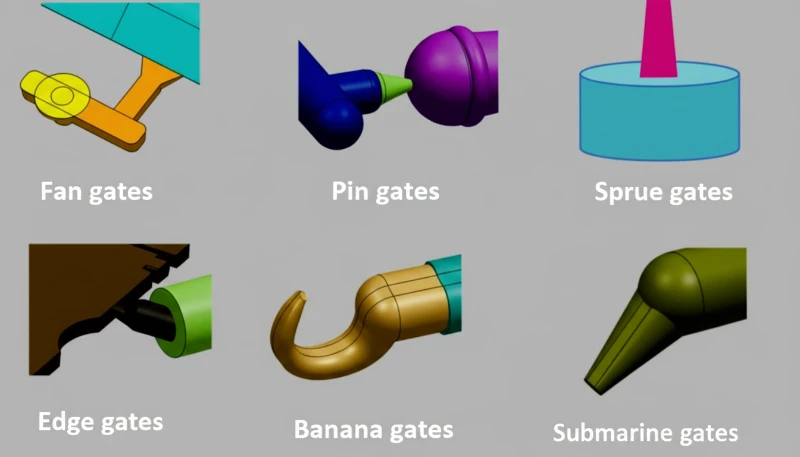
La ubicación y el tipo del punto de inyección requieren una consideración cuidadosa. El punto de inyección es el lugar por el que el plástico fundido entra en la cavidad, y su ubicación determina el patrón de flujo, la posición de las líneas de soldadura y la distribución de la presión de compactación, factores que afectan a la geometría final. Un solo punto de inyección lateral crea un flujo unidireccional que favorece el paralelismo en la dirección del flujo. Varios puntos de inyección pueden equilibrar el llenado, pero introducen líneas de soldadura que crean puntos débiles y discontinuidades geométricas.
El equipo de calidad de ZetarMold incluye más de 10 especialistas de QC que siguen un flujo de inspección de 6 pasos, con IQC, controles durante el proceso y OQC final, para verificar el cumplimiento de las tolerancias geométricas en cada lote de producción.
¿Cómo se miden e inspeccionan las tolerancias geométricas en piezas moldeadas?
Las CMMs, los escáneres ópticos y los calibres funcionales son los tres métodos principales para medir tolerancias geométricas en piezas plásticas moldeadas por inyección. Cada método presenta ventajas específicas según el tipo de tolerancia y el volumen de producción.
La medición CMM con palpadores es el método estándar para comprobar la posición, la perpendicularidad y el paralelismo. Sin embargo, las piezas de plástico son flexibles: la fuerza de contacto del palpador puede desviar la superficie e introducir errores de medición. El uso de CMM de baja fuerza de palpado, normalmente inferior a 50 mN, o de sondas láser sin contacto minimiza este problema. Para medir la planitud, el escaneado óptico con luz estructurada proporciona datos de toda la superficie, en lugar de los conjuntos de puntos dispersos de los palpadores, y ofrece una representación más precisa del estado real de la superficie.
El control funcional sigue siendo el método más práctico para la producción de gran volumen. Un calibre pasa/no pasa que simule el componente acoplado proporciona un resultado de aceptación o rechazo directamente relacionado con la función del conjunto. Aunque los calibres no indican exactamente cuánta desviación geométrica existe, son rápidos, repetibles y requieren una destreza mínima del operario, por lo que resultan ideales para la inspección durante el proceso en la planta de producción.

¿Cuáles son los rangos realistas de tolerancia geométrica para piezas moldeadas por inyección?
Los intervalos de tolerancia geométrica para piezas moldeadas por inyección suelen situarse entre 0 y 1 mm, según el tipo de tolerancia, el material y la geometría de la pieza. La tabla siguiente presenta intervalos prácticos basados en la experiencia del sector y en referencias de tolerancias estándar para el moldeo por inyección.
| Tipo de tolerancia | Precisión (tolerancias estrechas) | Estándar (Normal) | Grueso (suelto) |
|---|---|---|---|
| Planitud (por cada 100 mm) | 0.05–0.10 mm | 0.10–0.30 mm | 0.30–0.60 mm |
| Rectitud (por 100 mm) | 0.05–0.10 mm | 0.10–0.25 mm | 0.25–0.50 mm |
| Circularidad (diámetro) | 0.03–0.08 mm | 0.08–0.15 mm | 0.15–0.30 mm |
| Perpendicularidad (por 100 mm) | 0.05–0.10 mm | 0.10–0.25 mm | 0.25–0.50 mm |
| Paralelismo (por 100 mm) | 0.08–0.15 mm | 0.15–0.35 mm | 0.35–0.70 mm |
| Posición (RFS) | Diámetro: Ø0.10–0.20 mm | Diámetro Ø0.20–0.50 mm | Diámetro Ø0.50–1.00 mm |
| Perfil de una superficie | 0.10–0.20 mm | 0.20–0.50 mm | 0.50–1.00 mm |
Estos rangos asumen condiciones de procesamiento estándar con un diseño de molde optimizado. Lograr la columna de ‘Precisión’ generalmente requiere características de herramientas especializadas como enfriamiento conforme, sensores de presión en el molde y posiblemente accesorios posteriores al molde. La columna ‘Estándar’ representa lo que un molde bien diseñado que se ejecuta en una máquina de moldeo por inyección moderna puede producir de manera consistente. La columna ‘Gruesa’ es apropiada para características estéticas o estructurales no críticas. diseño de moldes
"Los canales de refrigeración conformales del molde pueden mejorar la planitud hasta un 40%."True
Los canales de refrigeración conformados siguen el contorno de la pieza y proporcionan una refrigeración más uniforme que reduce los gradientes térmicos y el alabeo resultante. Los estudios muestran mejoras de planitud del 30-50% frente a los canales taladrados convencionales.
"Los materiales reforzados con fibra de vidrio siempre mejoran la estabilidad dimensional y la tolerancia geométrica."False
Las fibras de vidrio mejoran la rigidez y reducen la contracción general, pero introducen una contracción anisotrópica que puede empeorar el alabeo y la planitud. La orientación de las fibras depende de la dirección del flujo, por lo que el paralelismo y la planitud pueden degradarse en determinadas orientaciones.
¿Por qué deberías discutir los requisitos de tolerancia geométrica con tu proveedor de moldeo desde el principio?
Los mayores problemas de tolerancia geométrica que vemos en nuestra fábrica no se deben a un moldeo deficiente, sino a especificaciones deficientes. Los diseñadores que fijan las tolerancias sin consultar al proveedor del molde de inyección suelen especificar tolerancias demasiado estrictas para ser realistas o mal orientadas hacia características no críticas. Ambos errores cuestan dinero.
La colaboración temprana entre el equipo de diseño y el proveedor de moldeo permite varias optimizaciones críticas. Primero, el proveedor puede ejecutar simulaciones de flujo del molde para validar si las tolerancias especificadas son alcanzables con la geometría y el material dados. Segundo, el equipo de utillaje puede optimizar la ubicación de la compuerta, la disposición de la refrigeración y la estrategia de expulsión para centrarse en las características geométricas más críticas. Tercero, el equipo de calidad puede diseñar protocolos y dispositivos de inspección que concentren el esfuerzo de medición en las características más importantes para la función.
Gracias a nuestras instalaciones internas de fabricación de moldes, con capacidad para más de 100+ conjuntos de moldes al mes, podemos iterar rápidamente el diseño del utillaje para obtener los mejores resultados posibles de tolerancia geométrica. Nuestros sistemas de calidad certificados conforme a ISO 9001, ISO 13485, ISO 14001 e ISO 45001 garantizan el mantenimiento de los requisitos de tolerancia geométrica durante toda la producción, desde la primera pieza hasta la millonésima.
¿Necesitas piezas moldeadas por inyección de precisión con tolerancias geométricas ajustadas?
ZetarMold es un fabricante con sede en Shanghái que suministra piezas de precisión moldeadas por inyección con tolerancias geométricas estrictas y más de 20 años de experiencia. Nuestros 8 ingenieros sénior colaboran con usted desde la fase de diseño para optimizar la geometría de la pieza, la selección de materiales y el diseño del utillaje con el fin de obtener los mejores resultados dimensionales. Tanto si necesita superficies planas de sellado dentro de 0.1 mm como tolerancias de posición para orificios de montaje de precisión, nuestro equipo dispone de la experiencia y los equipos necesarios. Solicite hoy un presupuesto gratuito y permítanos ayudarle a especificar y alcanzar las tolerancias geométricas adecuadas para su proyecto.
Preguntas frecuentes sobre tolerancias geométricas en el moldeo por inyección
Preguntas frecuentes
¿Cuál es la diferencia entre tolerancias dimensionales y geométricas?
Las tolerancias dimensionales controlan la variación admisible en una única medida lineal, como longitud, anchura o diámetro, expresada como un intervalo positivo o negativo. En cambio, las tolerancias geométricas controlan la forma, orientación o relación espacial de una característica: la planitud de una superficie, la perpendicularidad entre dos caras o la precisión de la posición de un orificio respecto a una referencia. En las piezas moldeadas por inyección, las tolerancias geométricas suelen ser más críticas que las dimensionales porque determinan directamente si los componentes encajan y funcionan correctamente en el montaje. En la práctica, la mayoría de los planos de piezas necesitan ambos tipos para comunicar por completo la intención del diseño.
¿Puede el moldeo por inyección alcanzar las mismas tolerancias geométricas que el mecanizado CNC?
En general, no. El mecanizado CNC puede mantener de forma habitual tolerancias geométricas de 0.01-0.05 mm porque la herramienta de corte crea directamente la geometría con una variabilidad mínima del comportamiento del material. El moldeo por inyección implica contracción del material, alabeo y variabilidad del proceso, lo que hace que las tolerancias inferiores a 0.05 mm resulten poco prácticas para la mayoría de las geometrías y materiales. Sin embargo, el moldeo por inyección es mucho más económico para la producción de gran volumen, incluso con tolerancias algo más amplias. La clave es diseñar piezas que funcionen de forma fiable dentro del intervalo de tolerancias geométricas que el moldeo puede ofrecer de manera constante, en lugar de obligarlo a igualar las capacidades del mecanizado.
¿Cómo afecta el tamaño de la pieza a la tolerancia geométrica alcanzable?
Las piezas más grandes son más difíciles de mantener dentro de tolerancias geométricas estrechas porque la contracción se acumula a lo largo de distancias mayores y el enfriamiento desigual se acentúa. Una planitud de 0.1 mm sobre 50 mm es alcanzable para la mayoría de los plásticos de ingeniería, pero esos mismos 0.1 mm sobre 300 mm resultan extremadamente difíciles en materiales semicristalinos. Las especificaciones de tolerancia deben escalar con el tamaño de la característica, a menudo expresado como porcentaje o valor por unidad de longitud. Una directriz práctica consiste en prever una capacidad de planitud de aproximadamente 0.1 a 0.2 por ciento de la longitud de la característica para materiales amorfos y de 0.2 a 0.4 por ciento para materiales semicristalinos.
¿Cuál es el error de tolerancia geométrica más habitual en los planos de piezas de plástico?
El error más común es aplicar tolerancias excesivas: especificar tolerancias geométricas más estrechas de lo que exigen los requisitos funcionales. Esto eleva el coste del utillaje, aumenta la tasa de desperdicio y ralentiza el rendimiento de la inspección sin aportar ninguna ventaja al producto final. El segundo error más común es seleccionar incorrectamente los datums cuando las características elegidas como datum no son estables, accesibles o funcionalmente relevantes para la medición. Ambos errores suelen deberse a la aplicación de prácticas de tolerancias propias del mecanizado de metales a piezas de plástico sin tener en cuenta las diferencias fundamentales de su comportamiento dimensional durante y después de la producción.
¿Mejora las tolerancias geométricas el uso de una máquina de moldeo por inyección de mayor presión?
Aumentar únicamente la presión de inyección no mejora la precisión geométrica. La presión de compactación debe optimizarse cuidadosamente para cada combinación de pieza y material. Una presión insuficiente provoca llenados incompletos y rechupes, mientras que una presión excesiva causa rebaba, sobrecompactación y tensiones internas que generan alabeo e inestabilidad dimensional. La optimización del proceso mediante principios de moldeo científico, incluidas las etapas desacopladas de llenado y compactación con sensores de presión y temperatura, es mucho más eficaz que limitarse a aumentar el tonelaje de la máquina o la presión de inyección sin un método sistemático.
¿Cuánto tiempo después del moldeo deben medirse las tolerancias geométricas?
Para la mayoría de los plásticos de ingeniería, debe esperar al menos 24 horas después del moldeo antes de realizar mediciones geométricas críticas. Algunos materiales semicristalinos, como el nailon y el PEEK, continúan estabilizándose dimensionalmente durante un máximo de 48-72 horas debido a la poscristalización y la relajación de tensiones en curso. Los materiales amorfos, como el policarbonato y el ABS, se estabilizan más rápido, pero aun así se benefician de un periodo de equilibrado mínimo de 12 a 24 horas. Medir demasiado pronto genera resultados engañosos que no reflejan la geometría final de la pieza y puede conducir a ajustes incorrectos del proceso que empeoren la calidad.
¿Se puede utilizar GD&T en moldes de inyección impresos en 3D para prototipos?
Los moldes impresos en 3D, como los fabricados con resina SLA o mediante fusión en lecho de polvo metálico, pueden producir piezas prototipo para ensayos de forma y ajuste. Sin embargo, la capacidad de tolerancia geométrica es considerablemente más amplia que la de los moldes de acero de producción porque los moldes impresos tienen menor conductividad térmica, superficies de cavidad menos precisas y una resistencia a la presión limitada. Cabe esperar tolerancias entre 3 y 5 veces más amplias que las que puede lograr un molde de acero para herramientas endurecido. Las indicaciones de GD&T en las piezas prototipo deben marcarse claramente como preliminares y reevaluarse al pasar al utillaje de producción fabricado con acero endurecido.
¿Qué papel desempeña la temperatura del molde en el control de las tolerancias geométricas?
La temperatura del molde afecta directamente a la velocidad de refrigeración, al comportamiento de cristalización y a la formación de tensiones residuales, factores que influyen en la precisión geométrica final de la pieza moldeada. Las temperaturas de molde más altas generan una refrigeración más uniforme y menores tensiones internas, lo que normalmente mejora la planitud y el control de la deformación. Sin embargo, una temperatura de molde más alta también aumenta el tiempo de ciclo y el coste de producción. En los materiales semicristalinos, la temperatura del molde también afecta al grado de cristalización, que a su vez influye en la magnitud de la contracción. Determinar la temperatura óptima del molde exige equilibrar la calidad geométrica, la eficiencia de producción y el coste.
ASME Y14.5: ASME Y14.5 se refiere al estándar nacional estadounidense para dimensionamiento y tolerancias geométricas, publicado por la Sociedad Estadounidense de Ingenieros Mecánicos. ↩
ISO 1101: ISO 1101 se refiere a la norma internacional para especificaciones geométricas de productos (GPS): tolerancias geométricas, tolerancias de forma, orientación, ubicación y excentricidad. ↩
Simulación del flujo del molde: la simulación del flujo del molde se refiere al análisis computacional del proceso de moldeo por inyección que predice el patrón de llenado, la distribución de la presión y la deformación antes de la fabricación del molde. ↩