Geometrische Toleranzen — die Grenzwerte fuer Form, Orientierung, Lage und Rundlauf von Merkmalen an einem Spritzgussteil — entscheiden darueber, ob eine Komponente perfekt einrastet oder im Ausschuss landet. Anders als einfache Plus/Minus-Masstoleranzen verwendet die geometrische Produktspezifikation (GD&T) eine standardisierte Symbolsprache gemaess ASME Y14.51 und ISO 11012, um die Konstruktionsabsicht eindeutig auszudruecken. Wer Kunststoffteile fuer Automobil-, Medizin- oder Unterhaltungselektronikanwendungen spezifiziert, muss geometrische Toleranzen beherrschen — sie gehoeren zum grundlegenden Ingenieurwissen.
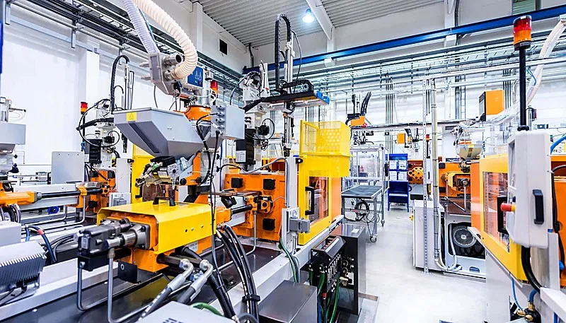
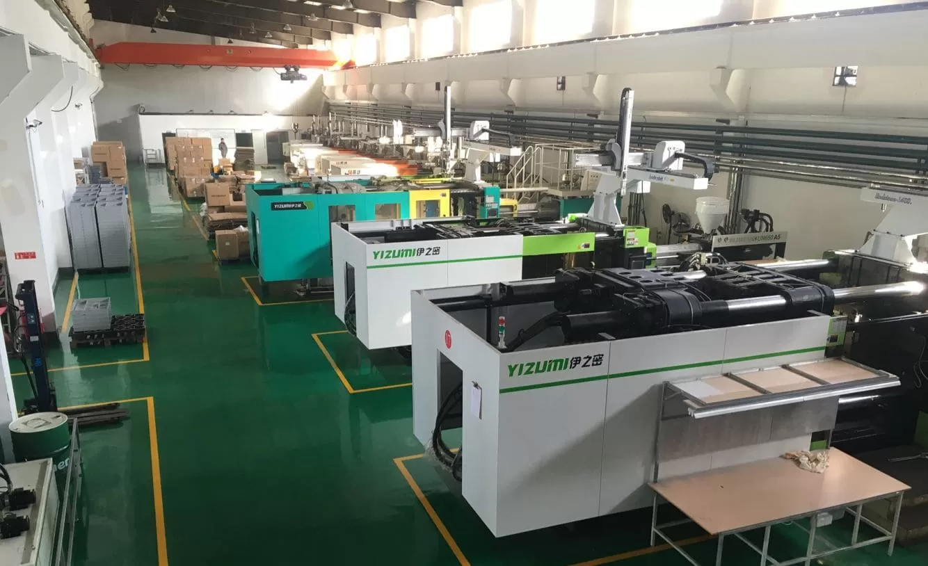
In unserem Werk in Shanghai betreiben wir 47 Spritzgießmaschinen von 90T bis 1850T und fertigen Teile mit engen geometrischen Vorgaben für Kunden weltweit. In 20+ Jahren Erfahrung mit 400+ Kunststoffmaterialien haben wir aus erster Hand erlebt, wie eine korrekte GD&T-Spezifikation kostspielige Streitigkeiten zwischen Konstrukteuren, Werkzeugbauern und Qualitätsteams verhindert. Dieser Leitfaden erläutert die wichtigsten geometrischen Toleranzarten für das Spritzgießen, zeigt ihre Relevanz für Kunststoffteile und gibt praktische Tipps aus der Fertigung.
- GD&T verwendet standardisierte Symbole (ASME Y14.5 / ISO 1101), um Form, Orientierung, Lage und Rundlauf zu definieren.
- Ebenheit und Geradheit sind die kritischsten geometrischen Toleranzen für Spritzgussteile.
- Materialschwindung und Verzug machen geometrische Toleranzen schwerer einzuhalten als bei der Metallbearbeitung.
- Die Bezugselementauswahl muss die funktionale Montage widerspiegeln – nicht nur die Bearbeitungsbequemlichkeit.
- Eine Überdimensionierung geometrischer Toleranzen treibt Werkzeug- und Prüfkosten in die Höhe, ohne einen Mehrwert zu schaffen.
Was sind geometrische Toleranzen und warum sind sie beim Spritzgießen wichtig?
Dieser Abschnitt erläutert die Hauptkategorien geometrischer Toleranzen und ihre Bedeutung beim Spritzgießen. Geometrische Toleranzen begrenzen zulässige Abweichungen von Form, Orientierung und Position eines Teils, die lineare Maße allein nicht erfassen. Eine Bohrung kann den richtigen Durchmesser haben und dennoch falsch positioniert sein; eine Fläche kann die richtige Dicke aufweisen, aber zum Abdichten zu stark verzogen sein. GD&T bildet diese Realitäten mit 14 Toleranzarten in fünf Kategorien ab: Form, Orientierung, Position, Rundlauf und Profil.
Beim Spritzguss sind geometrische Toleranzen besonders wichtig, weil Kunststoffteile waehrend des Abkuehlens schrumpfen, sich verziehen und innere Spannungen entwickeln. Ein beim Auswerfen einwandfreies Teil kann sich in den folgenden 24 bis 48 Stunden verformen, wenn Restspannungen abgebaut werden. Die festgelegte geometrische Toleranz muss daher nicht nur den Formprozess, sondern auch Massaenderungen danach beruecksichtigen. Eine Ebenheitstoleranz von 0,1 mm bei einem 150 mm grossen Polycarbonatgehaeuse kann beispielsweise eine besondere Anschnittgestaltung, optimierten Nachdruck und moeglicherweise eine Vorrichtung zum Fixieren waehrend der Abkuehlung erfordern.
Die Norm ASME Y14.5 definiert in den Vereinigten Staaten die vollständige Symbolsprache für GD&T, während ISO 1101 international dieselbe Funktion erfüllt. Beide Normen verwenden einen Toleranzrahmen — einen rechteckigen Kasten, der das Symbol des geometrischen Merkmals, den Toleranzwert und etwaige Bezugsangaben enthält. Das Lesen und Anwenden dieser Rahmen zu beherrschen, ist die Grundlage für die Kommunikation von Toleranzanforderungen an Ihren Spritzgießwerkzeuglieferanten.
Welche GD&T-Symbole sind für Kunststoffspritzgussteile am relevantesten?
Nicht alle 14 GD&T-Symbole sind für den Spritzguss gleich relevant. In der Praxis decken wenige geometrische Toleranzen den Großteil der Angaben auf Kunststoffteilzeichnungen ab. Es folgt eine Rangfolge der am häufigsten verwendeten Symbole und ihrer Bedeutung für Formteile.
| GD&T-Symbol | Kategorie | Typische Anwendung | Schwierigkeit der Einhaltung |
|---|---|---|---|
| Ebenheit | Form | Dichtflächen, Montageflächen | Hoch (Verzug) |
| Geradheit | Form | Rippen, Kanten, zylindrische Merkmale | Mittel |
| Zylindrizität | Form | Zylindrische Bolzen, Löcher | Mittel |
| Rechtwinkligkeit | Orientierung | Bolzen zur Fläche, Wand zum Flansch | Mittel-Hoch |
| Parallelität | Orientierung | Gegenüberliegende Wände, Schnappverbindungsmerkmale | Hoch |
| Position | Standort | Bohrungsmuster, Befestigungspunkte | Mittel |
| Konzentrizität | Standort | Rotierende Merkmale, Lagersitze | Sehr hoch |
| Profil einer Fläche | Profil | Komplexe gekrümmte Flächen | Hoch |
Ebenheit ist wohl die wichtigste geometrische Toleranz für Spritzgussteile. Eine Dichtfläche, die sich auch nur 0,15 mm wölbt, kann undicht werden. Eine Montagefläche, die sich um 0,2 mm verzieht, kann zu Montagefehlausrichtungen führen. Nach unserer Erfahrung machen Ebenheitsprobleme etwa 30-40% aller geometrischen Abweichungen bei Spritzgussteilen aus. Die Ursachen sind meist ungleichmäßige Abkühlung, ungünstige Angussplatzierung oder Materialschwindung, die beim Werkzeugdesign nicht korrekt simuliert wurde.
Die Positionstoleranz ist der nächstkritische Faktor. Bei einer Anordnung von Montagebohrungen oder Schnapphaken entscheidet deren relative Lage darüber, ob sich die Baugruppe montieren lässt. Die Positionstoleranz ist häufig nützlicher als einzelne Koordinatentoleranzen, da sie eine Bonustoleranz aus dem Istmaß des Merkmals ermöglicht — besonders wertvoll bei Kunststoffteilen, deren Bohrungsdurchmesser infolge der Schwindung variieren können.
Wie beeinflusst die Materialwahl die geometrische Toleranz beim Spritzgießen?
Das gewählte Material hat einen direkten und oft dramatischen Einfluss auf die geometrischen Toleranzen, die realistisch eingehalten werden können. Amorphe Materialien wie Polycarbonat (PC) und ABS neigen dazu, gleichmäßiger zu schrumpfen und eine bessere Ebenheit beizubehalten als teilkristalline Materialien wie Nylon (PA6, PA66) oder POM, die eine signifikante kristallisationsbedingte Schrumpfung durchlaufen. Glasfaserverstärkte Verbindungen erschweren die Sache weiter, da die Faserorientierung eine anisotrope Schrumpfung verursacht – das Teil schrumpft entlang der Fließrichtung anders als senkrecht dazu.
Ein Praxisbeispiel: Bei einer flachen Abdeckung von 200 mm x 150 mm aus PA66-GF30 (30% glasfaserverstaerktes Nylon 66) koennte die Moldflow-Simulation3 eine Schwindung von 0,6% in Fliessrichtung und 0,3% quer dazu vorhersagen — ein Verhaeltnis von 2:1. Eine Ebenheit von 0,1 mm waere dann ohne aussergewoehnliche Massnahmen wie Vorrichtungen in der Form oder nachtraegliches Tempern fuer den Werkstoff kaum erreichbar. Realistischer waere in diesem Fall eine Ebenheitstoleranz von 0,3–0,5 mm.
Hier schafft ein erfahrener Spritzgussformenlieferant echten Mehrwert. Mit 8 erfahrenen Ingenieuren und Erfahrung mit 400+ Werkstoffen helfen wir Kunden zu verstehen, welche geometrischen Toleranzen sich bei ihrem spezifischen Werkstoff, ihrer Bauteilgeometrie und ihrem Produktionsvolumen erreichen lassen. Die Vorgabe physikalisch nicht einhaltbarer Toleranzen verbessert die Qualität nicht, sondern erhöht lediglich Ausschussquote und Kosten.
"GD&T kann Toleranzen festlegen, die die Materialschwindung nach dem Formen berücksichtigen."True
Durch die Kombination von GD&T mit Daten aus der Formfüllsimulation können Konstrukteure die Geometrie nach der Schwindung vorhersagen und Toleranzen festlegen, die den endgültigen Gleichgewichtszustand des Bauteils und nicht nur seinen Zustand unmittelbar nach dem Formen widerspiegeln.
"Engere geometrische Toleranzen ergeben immer bessere Teile."False
Zu enge Toleranzen erhöhen Werkzeugkosten, Prüfzeit und Ausschussquote, ohne die Funktion zu verbessern. Die richtige Toleranz ist die größte, die Montage- und Funktionsanforderungen noch erfüllt.
Welche Normen regeln geometrische Toleranzen für spritzgegossene Kunststoffteile?
Geometrische Tolerierungsnormen werden weltweit hauptsächlich durch zwei Regelwerke bestimmt: ASME Y14.5 und ISO 1101. ASME Y14.5 ist in Nordamerika vorherrschend, während ISO 1101 zusammen mit ISO 5458 und ISO 5459 in Europa und Asien verwendet wird. Beide Normen definieren dieselben Grundkonzepte, unterscheiden sich jedoch in einigen Einzelheiten der Darstellung und in Standardregeln.
Speziell für Spritzgussteile enthält ISO 20457:2018 zusätzliche Leitlinien zu Maßtoleranzen von Formteilen, einschließlich eines Klassifizierungssystems, das werkzeugbezogene Faktoren wie Bauteilgeometrie, Anschnittposition und Materialverhalten berücksichtigt. Die Norm trägt der grundlegend anderen Toleranzfähigkeit von Kunststoffteilen gegenüber zerspanten Metallteilen Rechnung und erkennt an, dass GD&T auf Zerspanungsniveau bei spritzgegossenen Kunststoffen wirtschaftlich unrealistisch ist.
Geben Sie bei Zeichnungen für Spritzgussangebote immer die verwendete Norm an. Ein unter ASME Y14.5 interpretierter Toleranzrahmen kann insbesondere bei Positionstoleranzen und der Verwendung von Bezügen andere Ergebnisse liefern als derselbe Rahmen nach ISO 1101. Unterschiedliche Normauslegungen zählen zu den häufigsten Ursachen für Qualitätsstreitigkeiten zwischen Einkäufern und Spritzgießern.
Wie gibt man geometrische Toleranzen auf Zeichnungen von Spritzgussteilen vor?
Zur Spezifikation geometrischer Toleranzen sind drei Elemente erforderlich: Toleranzart, Toleranzwert und Bezugsrahmen. Der Bezugsrahmen ist wohl das wichtigste – und am häufigsten falsch angewandte – Element. Bezüge definieren die Referenzflächen, von denen alle weiteren Messungen ausgehen. Bei Spritzgussteilen muss die Auswahl der Bezüge berücksichtigen, wie das Teil geprüft wird, nicht nur, wie es funktioniert.
Ein häufiger Fehler besteht darin, die Trennlinie als Bezug zu verwenden. Die Trennlinie ist die Schnittstelle zwischen den Werkzeughälften. Sie scheint zwar eine stabile Referenz zu sein, kann jedoch im Laufe der Werkzeuglebensdauer Grat bilden, sich verschieben oder verschleißen. Besser ist es, funktionale Merkmale wie einen flachen Montagebund oder eine präzisionsgebohrte Bohrung als Bezugselemente festzulegen. Diese Merkmale werden direkt in den Werkzeugstahl eingearbeitet und bewahren ihre geometrische Integrität über Hunderttausende von Zyklen.
Ein praxistauglicher Spezifikationsablauf sieht so aus: Bestimmen Sie zuerst die Merkmale, die mit anderen Komponenten zusammenpassen muessen. Legen Sie danach die stabilsten und am besten zugaenglichen dieser Merkmale als Bezuege fest. Waehlen Sie anschliessend die groesstmoegliche geometrische Toleranz, die die Funktion noch sicherstellt. Stimmen Sie Ihre Angaben vor Abschluss der Zeichnung schliesslich mit Ihrem Spritzgusslieferanten ab — er kann beurteilen, was angesichts von Bauteilgeometrie, Werkstoff und Produktionsbedingungen realistisch erreichbar ist.
Was verursacht geometrische Toleranzabweichungen beim Spritzgießen?
Verzug, ungleichmäßige Kühlung, Entformungskräfte und Werkzeugverschleiß sind die Hauptursachen geometrischer Toleranzabweichungen beim Spritzgießen. Wer diese Ursachen versteht, kann realistische Toleranzen festlegen und maßstabilere Teile konstruieren.
Verzug ist der größte Feind geometrischer Toleranzen im Spritzguss. Er entsteht, wenn verschiedene Bereiche des Bauteils unterschiedlich schnell abkühlen und schwinden. Dünne Bereiche kühlen schneller ab als dicke. Anschnittnahe Bereiche erhalten mehr Nachdruck als anschnittferne Bereiche. Bei fasergefüllten Werkstoffen entstehen durch die Faserausrichtung Eigenspannungen, die sich beim Erreichen des Gleichgewichtszustands des Bauteils lösen. Das Ergebnis ist ein Bauteil, das im Werkzeug geometrisch korrekt war, bei einer Messung 24 Stunden später jedoch Verformungen aufweist.

Auch die Auswerfkräfte sind ein wesentlicher Faktor. Beim Abkühlen schrumpft das Bauteil auf den Werkzeugkern. Die Auswerferstifte müssen das Bauteil abdrücken, wobei diese Kraft dünne Wände oder empfindliche Merkmale vorübergehend verformen kann. Gut ausgelegte Auswerfersysteme verteilen die Kraft gleichmäßig, doch selbst eine optimale Auswerfung kann auf kritischen Oberflächen geometrische Abweichungen von weniger als einem Zehntelmillimeter verursachen.
Auch Werkzeugverschleiß und Wartung spielen eine Rolle. Nach 100,000+ Zyklen können Werkzeugoberflächen erodieren, insbesondere im Angussbereich und an Schiebekernen. Dieser allmähliche Verschleiß verändert die Abmessungen und kann dazu führen, dass geometrische Merkmale aus dem Toleranzbereich driften. Regelmäßige Werkzeugwartung und wiederkehrende Erstmusterprüfungen sind unerlässlich, um diese Abweichung zu erkennen, bevor sie die Produktionsqualität beeinträchtigt.
"Eine Formfüllsimulation kann die Ergebnisse geometrischer Toleranzen vor der Stahlbearbeitung prognostizieren."True
Moderne Formfüllsimulationsprogramme wie Moldflow und Moldex3D können Verzug, Schwindung und Faserorientierung hinreichend genau vorhersagen, um die Machbarkeit geometrischer Toleranzen bereits in der Konstruktionsphase zu validieren.
"Das Tempern nach dem Formen verbessert stets die Einhaltung geometrischer Toleranzen."False
Das Tempern baut innere Spannungen ab, kann bei unzureichender Regelung jedoch zusätzliche Verformungen verursachen. Bei manchen Materialien und Geometrien verschlechtert das Tempern sogar die Ebenheit oder Positionsgenauigkeit. Es muss für jeden Einzelfall bewertet werden.
Wie können Sie das Teiledesign für eine bessere Einhaltung geometrischer Toleranzen optimieren?
Gleichmäßige Wanddicke, geeignete Rippenproportionen und eine gezielte Angusspositionierung sind die wichtigsten Konstruktionsstrategien zur Einhaltung geometrischer Toleranzen. Diese Strategien verbessern die Maßstabilität, ohne die Kosten zu erhöhen.
Eine gleichmäßige Wanddicke ist die wichtigste konstruktive Einzelentscheidung für die geometrische Beherrschung. Wenn die Wanddicke innerhalb eines Bauteils erheblich variiert, schrumpfen dicke Bereiche stärker als dünne. Dadurch entstehen innere Spannungen, die Verzug verursachen. Bei einem kristallinen Werkstoff führt eine Wanddickenabweichung von mehr als 15-20% auf ebenen Flächen nahezu zwangsläufig zu geometrischen Abweichungen. Wo Dickenübergänge unvermeidbar sind, sollten allmähliche Rampen statt scharfer Stufen eingesetzt werden, um Spannungen gleichmäßiger zu verteilen.
Die Rippengestaltung beeinflusst auch die geometrischen Ergebnisse. Rippen erhöhen die Steifigkeit und tragen damit zur Ebenheit bei — sie erzeugen jedoch auch lokale dicke Bereiche, die stärker als die umgebende Wand schwinden. Halten Sie die Rippendicke bei den meisten Werkstoffen auf 50-60% der Nennwanddicke und vermeiden Sie sich kreuzende Rippen, die dicke Knoten bilden. Gewellte Wandabschnitte können bei höherer geometrischer Stabilität eine vergleichbare Steifigkeit wie konventionelle Rippen bieten.
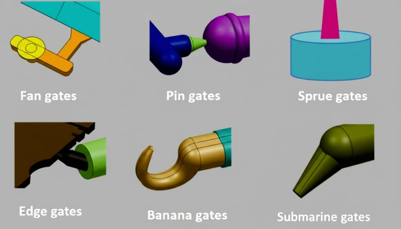
Position und Art des Anschnitts müssen sorgfältig gewählt werden. Am Anschnitt tritt der geschmolzene Kunststoff in die Kavität ein; seine Position bestimmt das Fließbild, die Lage der Bindenähte und die Verteilung des Nachdrucks — sämtliche Faktoren beeinflussen die endgültige Geometrie. Ein einzelner Kantenanschnitt erzeugt einen gerichteten Fluss, der die Parallelität in Fließrichtung begünstigt. Mehrere Anschnitte können die Füllung ausgleichen, erzeugen jedoch Bindenähte, die Schwachstellen und geometrische Diskontinuitäten bilden.
Das Qualitätsteam von ZetarMold umfasst 10+ QC-Spezialisten, die einen 6-stufigen Prüfablauf mit IQC, prozessbegleitenden Prüfungen und abschließender OQC befolgen, um bei jedem Produktionslauf die Einhaltung geometrischer Toleranzen zu verifizieren.
Wie misst und prüft man geometrische Toleranzen an Spritzgussteilen?
CMMs, optische Scanner und Funktionslehren sind die drei wichtigsten Methoden zur Messung geometrischer Toleranzen an Kunststoffspritzgussteilen. Jede Methode bietet abhängig von der Toleranzart und dem Produktionsvolumen spezifische Vorteile.
CMM-Messungen mit Tastsystemen sind der Standard für die Prüfung von Position, Rechtwinkligkeit und Parallelität. Kunststoffteile sind jedoch nachgiebig — die Kontaktkraft des Tasters kann die Oberfläche verformen und Messfehler verursachen. Der Einsatz von CMMs mit geringer Tastkraft (typischerweise unter 50 mN) oder berührungslosen Lasertastern minimiert dieses Problem. Bei der Ebenheitsmessung liefert optisches Scannen mit strukturiertem Licht vollflächige Daten anstelle der lückenhaften Punktsätze von Tastsystemen und vermittelt so ein genaueres Bild des tatsächlichen Oberflächenzustands.
Die Funktionsprüfung mit Lehren bleibt das praktischste Verfahren für die Großserienproduktion. Eine Gut-/Ausschusslehre, die die Gegenkomponente simuliert, liefert ein Bestanden-/Nicht-bestanden-Ergebnis, das unmittelbar mit der Montagefunktion korreliert. Lehren zeigen zwar nicht das genaue Ausmaß einer geometrischen Abweichung, sind aber schnell, wiederholbar und erfordern nur geringe Bedienerqualifikation — damit eignen sie sich ideal für prozessbegleitende Prüfungen in der Fertigung.

Welche realistischen geometrischen Toleranzbereiche gibt es für spritzgegossene Teile?
Geometrische Toleranzbereiche für Spritzgussteile liegen je nach Toleranzart, Material und Bauteilgeometrie typischerweise zwischen 0 und 1 mm. Die folgende Tabelle enthält praxisgerechte Bereiche auf Grundlage von Branchenerfahrung und Standardtoleranzreferenzen für das Spritzgießen.
| Toleranzart | Präzision (eng) | Standard (üblich) | Grob (Locker) |
|---|---|---|---|
| Ebenheit (pro 100 mm) | 0.05–0.10 mm | 0.10–0.30 mm | 0.30–0.60 mm |
| Geradheit (pro 100 mm) | 0.05–0.10 mm | 0.10–0.25 mm | 0.25–0.50 mm |
| Rundheit (Durchmesser) | 0.03–0.08 mm | 0.08–0.15 mm | 0.15–0.30 mm |
| Rechtwinkligkeit (pro 100 mm) | 0.05–0.10 mm | 0.10–0.25 mm | 0.25–0.50 mm |
| Parallelität (pro 100 mm) | 0.08–0.15 mm | 0.15–0.35 mm | 0.35–0.70 mm |
| Stellung (RFS) | Durchmesser Ø0.10–0.20 mm | Durchmesser Ø0.20–0.50 mm | Durchmesser 0.50–1.00 mm |
| Profil einer Fläche | 0.10–0.20 mm | 0.20–0.50 mm | 0.50–1.00 mm |
Diese Bereiche setzen Standardprozessbedingungen und eine optimierte Formkonstruktion voraus. Werte in der Spalte „Praezision“ erfordern meist besondere Werkzeugmerkmale wie konturnahe Kuehlung, Forminnendrucksensoren und gegebenenfalls nachtraegliche Fixierung. Die Spalte „Standard“ beschreibt, was eine gut konstruierte Form auf einer modernen Spritzgiessmaschine dauerhaft leisten kann. „Grob“ eignet sich fuer unkritische optische oder strukturelle Merkmale.
"Konturnahe Kühlkanäle im Werkzeug können die Ebenheit um bis zu 40% verbessern."True
Konturnahe Kühlkanäle folgen der Bauteilkontur und sorgen für eine gleichmäßigere Kühlung, die Temperaturgradienten und den daraus entstehenden Verzug reduziert. Studien zeigen gegenüber herkömmlichen gebohrten Kanälen Verbesserungen der Ebenheit um 30-50%.
"Glasfasergefüllte Werkstoffe verbessern immer Maßstabilität und geometrische Toleranz."False
Glasfasern erhöhen die Steifigkeit und verringern die Gesamtschwindung, führen jedoch zu anisotroper Schwindung, die Verzug und Ebenheit verschlechtern kann. Die Faserausrichtung hängt von der Fließrichtung ab, sodass sich Parallelität und Ebenheit bei bestimmten Ausrichtungen tatsächlich verschlechtern können.
Warum sollten Sie geometrische Toleranzanforderungen frühzeitig mit Ihrem Spritzgießlieferanten besprechen?
Die größten geometrischen Toleranzprobleme in unserem Werk entstehen nicht durch schlechtes Spritzgießen, sondern durch mangelhafte Spezifikationen. Konstrukteure, die Toleranzen ohne Rücksprache mit ihrem Spritzgießwerkzeuglieferanten festlegen, definieren häufig unrealistisch enge Toleranzen oder wenden sie schlecht auf unkritische Merkmale an. Beide Fehler kosten Geld.
Die frühzeitige Zusammenarbeit zwischen Konstruktionsteam und Spritzgießlieferant ermöglicht mehrere entscheidende Optimierungen. Erstens kann der Lieferant Moldflow-Simulationen durchführen, um zu prüfen, ob die vorgegebenen Toleranzen mit der jeweiligen Geometrie und dem Werkstoff erreichbar sind. Zweitens kann das Werkzeugbauteam Anschnittposition, Kühlkanalanordnung und Auswerferstrategie auf die kritischsten geometrischen Merkmale ausrichten. Drittens kann das Qualitätsteam Prüfprotokolle und Vorrichtungen entwickeln, die den Messaufwand auf die funktionsrelevanten Merkmale konzentrieren.
Mit unserem internen Werkzeugbau, der monatlich mehr als 100 Werkzeugsätze fertigt, können wir die Werkzeugkonstruktion schnell iterieren und bestmögliche Ergebnisse bei geometrischen Toleranzen erreichen. Unsere nach ISO 9001, ISO 13485, ISO 14001 und ISO 45001 zertifizierten Qualitätssysteme stellen sicher, dass geometrische Toleranzanforderungen während der gesamten Produktion eingehalten werden — vom Erstmuster bis zum millionsten Teil.
Benötigen Sie präzise spritzgegossene Teile mit engen geometrischen Toleranzen?
ZetarMold ist ein Hersteller mit Sitz in Shanghai, der seit über 20 Jahren Präzisionsspritzgussteile mit engen geometrischen Toleranzen fertigt. Unsere 8 erfahrenen Ingenieure arbeiten bereits in der Konstruktionsphase mit Ihnen zusammen, um Bauteilgeometrie, Werkstoffauswahl und Werkzeugauslegung für optimale Maßhaltigkeit zu optimieren. Ob Sie ebene Dichtflächen innerhalb von 0.1 mm oder Positionstoleranzen für präzise Montagebohrungen benötigen: Unser Team verfügt über das Fachwissen und die Ausrüstung, um Ihre Anforderungen zu erfüllen. Fordern Sie noch heute ein kostenloses Angebot an. Wir unterstützen Sie dabei, die richtigen geometrischen Toleranzen für Ihr Projekt festzulegen und zuverlässig zu erreichen.
Häufig gestellte Fragen zu geometrischen Toleranzen beim Spritzgießen
Häufig gestellte Fragen
Worin unterscheiden sich Maßtoleranzen und geometrische Toleranzen?
Maßtoleranzen begrenzen die zulässige Abweichung eines einzelnen linearen Maßes wie Länge, Breite oder Durchmesser, ausgedrückt als Plus-Minus-Bereich. Geometrische Toleranzen begrenzen dagegen Form, Orientierung oder räumliche Beziehung eines Merkmals: wie eben eine Fläche ist, wie rechtwinklig zwei Flächen zueinander stehen oder wie genau eine Bohrung relativ zu einem Bezug positioniert ist. Bei spritzgegossenen Bauteilen sind geometrische Toleranzen häufig kritischer als Maßtoleranzen, da sie unmittelbar bestimmen, ob Komponenten bei der Montage zusammenpassen und ordnungsgemäß funktionieren. In der Praxis benötigen die meisten Bauteilzeichnungen beide Toleranzarten, um die Konstruktionsabsicht vollständig zu vermitteln.
Kann Spritzgießen die gleichen geometrischen Toleranzen wie CNC-Bearbeitung erreichen?
Im Allgemeinen nicht. Bei der CNC-Bearbeitung lassen sich geometrische Toleranzen von 0.01-0.05 mm routinemäßig einhalten, weil das Schneidwerkzeug die Geometrie direkt erzeugt und das Materialverhalten nur geringe Schwankungen aufweist. Beim Spritzguss führen Materialschwindung, Verzug und Prozessschwankungen dazu, dass Toleranzen unter 0.05 mm für die meisten Bauteilgeometrien und Materialien nicht praktikabel sind. Für die Großserienfertigung ist der Spritzguss jedoch selbst bei etwas größeren Toleranzen deutlich wirtschaftlicher. Entscheidend ist, Bauteile so auszulegen, dass sie innerhalb des geometrischen Toleranzbereichs, den der Spritzguss dauerhaft erreichen kann, zuverlässig funktionieren, statt vom Spritzguss die Genauigkeit einer spanenden Bearbeitung zu verlangen.
Wie beeinflusst die Bauteilgröße die erreichbare geometrische Toleranz?
Bei größeren Teilen sind enge geometrische Toleranzen schwieriger einzuhalten, da sich die Schwindung über längere Strecken summiert und ungleichmäßige Kühlung stärker ins Gewicht fällt. Eine Ebenheit von 0.1 mm über 50 mm ist für die meisten technischen Kunststoffe erreichbar, dieselben 0.1 mm über 300 mm sind bei teilkristallinen Werkstoffen jedoch äußerst schwierig. Toleranzangaben sollten mit der Merkmalsgröße skalieren und werden häufig als Prozentsatz oder längenbezogener Wert ausgedrückt. Als praktische Richtlinie ist bei amorphen Werkstoffen mit einer Ebenheit von etwa 0.1 bis 0.2 Prozent der Merkmalslänge und bei teilkristallinen Werkstoffen mit 0.2 bis 0.4 Prozent zu rechnen.
Was ist der häufigste Fehler bei geometrischen Toleranzen in Kunststoffteilzeichnungen?
Der häufigste Fehler ist die Übertolerierung: geometrische Toleranzen werden enger festgelegt, als es die funktionalen Anforderungen verlangen. Dies erhöht die Werkzeugkosten und Ausschussquote und verlangsamt den Prüfdurchsatz, ohne dem Endprodukt zu nutzen. Der zweithäufigste Fehler ist eine falsche Bezugsauswahl, bei der die gewählten Bezugsmerkmale nicht stabil, zugänglich oder funktional relevant für die Messung sind. Beide Fehler entstehen häufig dadurch, dass Toleranzpraktiken aus der Metallbearbeitung auf Kunststoffteile übertragen werden, ohne die grundlegenden Unterschiede im Maßverhalten von Formteilen während und nach der Produktion zu berücksichtigen.
Verbessert eine Spritzgießmaschine mit höherem Druck die geometrischen Toleranzen?
Ein höherer Einspritzdruck allein verbessert die geometrische Genauigkeit nicht. Der Nachdruck muss für jede Teile- und Materialkombination sorgfältig optimiert werden. Zu wenig Druck verursacht unvollständige Füllung und Einfallstellen, zu viel Druck führt zu Gratbildung, Überpackung und inneren Spannungen, die Verzug und Maßinstabilität verursachen. Eine Prozessoptimierung nach den Grundsätzen des wissenschaftlichen Spritzgießens, einschließlich getrennter Füll- und Nachdruckphasen mit Druck- und Temperatursensoren, ist wesentlich wirksamer als eine unsystematische Erhöhung von Maschinentonnage oder Einspritzdruck.
Wie bald nach dem Spritzgießen sollten geometrische Toleranzen gemessen werden?
Bei den meisten technischen Kunststoffen sollten Sie nach dem Spritzgießen mindestens 24 Stunden warten, bevor Sie kritische geometrische Messungen durchführen. Einige teilkristalline Werkstoffe wie Nylon und PEEK stabilisieren sich aufgrund fortlaufender Nachkristallisation und Spannungsrelaxation bis zu 48-72 Stunden weiter. Amorphe Werkstoffe wie Polycarbonat und ABS stabilisieren sich schneller, profitieren aber dennoch von einer Ausgleichszeit von mindestens 12 bis 24 Stunden. Zu frühes Messen liefert irreführende Ergebnisse, die nicht der endgültigen Teilegeometrie entsprechen, und kann falsche Prozessanpassungen auslösen, die die Qualität tatsächlich verschlechtern.
Kann GD&T bei 3D-gedruckten Spritzgießformen für Prototypen eingesetzt werden?
3D-gedruckte Werkzeuge, etwa aus SLA-Harz oder durch Metall-Pulverbettfusion, können Prototypenteile für Form- und Passungsprüfungen herstellen. Ihre geometrischen Toleranzen sind jedoch deutlich größer als bei Produktionswerkzeugen aus Stahl, da gedruckte Werkzeuge eine geringere Wärmeleitfähigkeit, unpräzisere Kavitätsoberflächen und eine begrenzte Druckfestigkeit aufweisen. Rechnen Sie mit 3- bis 5-mal größeren Toleranzen als bei einem Werkzeug aus gehärtetem Werkzeugstahl. GD&T-Angaben an Prototypenteilen sollten eindeutig als vorläufig gekennzeichnet und beim Übergang zu Produktionswerkzeugen aus gehärtetem Stahl neu bewertet werden.
Welche Rolle spielt die Werkzeugtemperatur bei der Kontrolle geometrischer Toleranzen?
Die Werkzeugtemperatur beeinflusst unmittelbar die Abkühlgeschwindigkeit, das Kristallisationsverhalten und die Bildung von Eigenspannungen, die sich sämtlich auf die endgültige geometrische Genauigkeit des Formteils auswirken. Höhere Werkzeugtemperaturen führen zu einer gleichmäßigeren Abkühlung und geringeren inneren Spannungen, wodurch sich Ebenheit und Verzugsbeherrschung in der Regel verbessern. Eine höhere Werkzeugtemperatur verlängert jedoch auch die Zykluszeit und erhöht die Produktionskosten. Bei teilkristallinen Werkstoffen beeinflusst die Werkzeugtemperatur außerdem den Kristallisationsgrad, der wiederum das Ausmaß der Schwindung bestimmt. Die optimale Werkzeugtemperatur ergibt sich aus der Abwägung zwischen geometrischer Qualität, Produktionseffizienz und Kosten.
ASME Y14.5: ASME Y14.5 ist der von der American Society of Mechanical Engineers veroeffentlichte US-Standard fuer geometrische Bemassung und Tolerierung. ↩
ISO 1101: ISO 1101 ist die internationale Norm fuer geometrische Produktspezifikation (GPS), geometrische Tolerierung sowie Form-, Richtungs-, Orts- und Lauftoleranzen. ↩
Moldflow-Simulation: Eine Moldflow-Simulation ist die rechnergestuetzte Analyse des Spritzgussprozesses, die vor der Formherstellung Fuellverlauf, Druckverteilung und Verzug vorhersagt. ↩