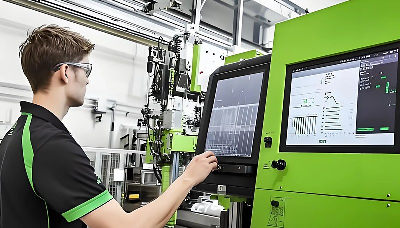
幾何公差 — 射出成形部品の形状、姿勢、位置、振れを制御する限界 — は、部品が完璧に組み合わさるか、スクラップ箱行きになるかの違いを生む。単純なプラスマイナスの寸法公差とは異なり、幾何公差(GD&T)は、以下で定義される標準化された記号言語を使用する。 ASME Y14.51 そして ISO 11012 設計意図を明確に伝達するためです。自動車、医療、民生電子機器アプリケーション向けのプラスチック部品を指定する場合、幾何公差を理解することは任意ではなく、コアとなるエンジニアリングスキルです。
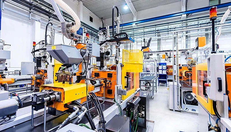
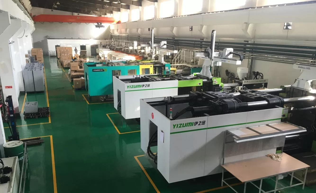
当社の上海工場では、90トンから1850トンまでの47台の射出成形機を稼働させ、世界中のクライアント向けに厳しい幾何公差管理を施した部品を生産している。400種類以上のプラスチック材料での20年以上の経験から、適切なGD&T指定が設計者、金型メーカー、品質チーム間のコストのかかる紛争を防ぐことを目の当たりにしてきた。本ガイドでは、射出成形において知っておくべき主要な幾何公差の種類を解説し、プラスチック部品にとって最も重要なものを説明し、生産現場からの実用的なヒントを共有する。
- GD&Tは、形状、姿勢、位置、振れを定義するために標準化された記号(ASME Y14.5 / ISO 1101)を使用します。
- 平面度と直線度は、射出成形部品にとって最も重要な幾何公差です。
- 材料収縮と反りにより、幾何公差は金属加工よりも維持が困難です。
- データムの選択は、加工の都合だけでなく、機能的な組み立てを反映する必要があります。
- 幾何公差を過度に指定すると、付加価値を生むことなく、金型製作コストと検査コストが上昇する。
幾何公差とは何か、また射出成形においてなぜ重要なのか?
本セクションでは、射出成形における幾何公差とその重要性、主要なカテゴリや選択肢について説明します。幾何公差は、線形寸法だけでは捉えきれない部品の形状、姿勢、位置の許容変動の限界です。穴は正しい直径であっても位置がずれている場合があり、表面は適切な厚さであってもシールできないほど歪んでいる可能性があります。GD&Tは、形状、姿勢、位置、振れ、輪郭の5つのカテゴリに分類される14種類の公差でこれらの現実に対応します。
で 射出成形幾何公差は特に重要です。なぜなら、プラスチック部品は冷却中に収縮、反り、内部応力を経験するからです。射出直後には完璧に見える部品でも、残留応力が緩和される次の24〜48時間で変形する可能性があります。これは、指定する幾何公差が成形プロセス自体だけでなく、成形後の寸法変化も考慮しなければならないことを意味します。例えば、150mmのポリカーボネートハウジングに0.1mmの平面度を指示する場合、特別なゲート設計、最適化された保圧、場合によっては冷却中に部品を拘束する治具が必要となるかもしれません。
ASME Y14.5規格は米国におけるGD&Tの完全な記号言語を定義しており、ISO 1101は国際的に同じ役割を果たしています。どちらの規格も、幾何特性記号、公差値、データム参照を含む長方形の枠である特性制御枠を使用します。これらの枠を読み取り適用する方法を理解することは、射出成形金型サプライヤーに公差要求を伝達する基礎となります。
プラスチック射出成形部品に関連性の高いGD&T記号はどれか?
14種類のGD&T記号すべてが射出成形に等しく関連するわけではありません。実際には、少数の幾何公差がプラスチック部品図面の指示の大部分を占めています。以下に、最も頻繁に使用される記号と、成形部品にとってそれらが重要な理由をランク付けして解説します。
| GD&T Symbol | Category | 代表的なアプリケーション | 維持の難易度 |
|---|---|---|---|
| 平面度 | 形状 | シール面、取付面 | 高(反り) |
| 直線度 | 形状 | リブ、エッジ、円筒形状 | ミディアム |
| 真円度 | 形状 | 円筒ボス、穴 | ミディアム |
| 垂直度 | オリエンテーション | ボス対面、壁対フランジ | ミディアム-ハイ |
| 平行度 | オリエンテーション | 対向壁、スナップフィット構造 | 高い |
| ポジション | 所在地 | 穴パターン、取り付け点 | ミディアム |
| 同心度 | 所在地 | 回転部品、ベアリング座面 | 非常に高い |
| 面の輪郭度 | 輪郭度 | 複雑な曲面 | 高い |
平坦度は、射出成形部品において最も重要な幾何公差であると言える。0.15mmでも反ってしまうシール面はリークを起こす可能性がある。0.2mm歪んだ取り付け面は組立時の不整合を引き起こす。当社の経験では、成形部品の幾何的不適合の約30-40%は平坦度の問題によるものである。根本原因は通常、不均一な冷却、不適切なゲート配置、または金型設計時に適切にシミュレーションされなかった材料収縮である。
位置公差は次に重要なものである。取り付け穴やスナップフィットクリップの配列がある場合、それらの相対位置は組立がうまくいくかどうかを決定する。位置公差は個々の座標公差よりも有用なことが多い。なぜなら、部品の実際のサイズからボーナス公差が許容されるからである。これは、収縮により穴径が変動しやすいプラスチック部品において特に価値がある。
材料選択は射出成形における幾何公差にどのような影響を与えるか?
選択する材料は、現実的に維持できる幾何公差に直接的かつしばしば劇的な影響を与える。ポリカーボネート(PC)やABSなどの非晶性材料は、ナイロン(PA6、PA66)やPOMなどの半結晶性材料よりも均一に収縮し、平坦度をより良く維持する傾向がある。半結晶性材料は結晶化による大きな収縮を伴う。ガラス繊維充填材はさらに複雑にする。なぜなら、繊維配向により異方性収縮が生じるからである。つまり、流れ方向とそれに垂直な方向で部品の収縮が異なる。
Consider a practical example: a 200 mm x 150 mm flat cover in PA66-GF30 (30% glass-filled nylon 66). The mold flow simulation3 might predict 0.6% shrinkage in the flow direction and 0.3% transverse — a 2:1 ratio. If you specify flatness of 0.1 mm, you are likely asking for something the material simply cannot deliver without extraordinary measures like in-mold fixtures or post-mold annealing. A more realistic flatness callout for this scenario would be 0.3-0.5 mm.
This is where an experienced injection mold supplier adds real value. With 8 senior engineers and experience across 400+ materials, we help customers understand what geometric tolerances are achievable for their specific material, part geometry, and production volume. Specifying tolerances that are physically impossible to hold does not improve quality — it only increases scrap rate and cost.
“GD&T can specify tolerances that account for material shrinkage after molding.”真
By combining GD&T with mold flow simulation data, designers can predict post-shrinkage geometry and specify tolerances that reflect the part’s final equilibrium state, not just its as-molded condition.
“Tighter geometric tolerances always produce better parts.”偽
Over-tolerancing increases tooling cost, inspection time, and scrap rate without improving functional performance. The right tolerance is the loosest one that still satisfies assembly and function requirements.
成形プラスチック部品の幾何公差を規定する標準は何か?
Geometric tolerancing standards are primarily governed by two frameworks worldwide: ASME Y14.5 and ISO 1101. ASME Y14.5 dominates in North America, while ISO 1101 (with companion standards ISO 5458 and ISO 5459) is used in Europe and Asia. Both standards define the same fundamental concepts but differ in some notation details and default rules.
For injection molded parts specifically, ISO 20457:2018 provides additional guidance on dimensional tolerances for molded parts, including a classification system that accounts for mold-related factors like part geometry, gate location, and material behavior. This standard recognizes that plastic parts have fundamentally different tolerance capability than machined metal parts, and that applying machining-grade GD&T to molded plastics is economically unrealistic.
When preparing drawings for injection molding quotes, always specify which standard you are using. A tolerance frame interpreted under ASME Y14.5 may yield different results than the same frame under ISO 1101, particularly for position tolerances and datum usage. Misalignment on standards interpretation is one of the most common sources of quality disputes between buyers and molders.

射出成形部品図面に幾何公差をどのように指定するか?
Three elements are needed to specify geometric tolerances: the tolerance type, the tolerance value, and the datum reference frame. The datum reference frame is arguably the most important — and most frequently misapplied — element. Datums define the reference surfaces from which all other measurements are taken. For injection molded parts, datum selection must consider how the part will be inspected, not just how it functions.
A common mistake is using the parting line as a datum. The parting line is the interface between the mold halves, and while it seems like a stable reference, it can flash, shift, or wear over the life of the mold. A better approach is to designate functional features — such as a flat mounting boss or a precision-bored hole — as datums. These features are directly machined into the mold steel and maintain their geometric integrity over hundreds of thousands of cycles.
Here is a practical specification workflow: First, identify the features that must mate with other components. Second, assign datums to the most stable and accessible of these features. Third, apply the loosest geometric tolerance that still guarantees function. Fourth, validate your callouts with your 射出成形サプライヤー before finalizing the drawing — they can tell you what is realistically achievable given the part geometry, material, and production constraints.
射出成形時に幾何公差の偏差が生じる原因は何か?
Warpage, uneven cooling, ejection forces, and mold wear are the primary causes of geometric tolerance deviations during injection molding. Understanding these causes helps you set realistic tolerances and design more dimensionally stable parts.
Warpage is the number-one enemy of geometric tolerance in injection molding. It occurs when different regions of the part cool and shrink at different rates. Thin sections cool faster than thick sections. Areas near the gate receive more packing pressure than areas far from the gate. Fiber-filled materials develop internal stresses from oriented fibers that release as the part equilibrates. The result is a part that was geometrically correct in the mold but distorted when measured 24 hours later.

Ejection forces are another significant factor. As the part cools, it shrinks onto the mold core. The ejector pins must push the part off, and this force can temporarily distort thin walls or delicate features. Well-designed ejector systems distribute force evenly, but even optimal ejection can introduce sub-tenth-millimeter geometric deviations on critical surfaces.
Mold wear and maintenance also play a role. After 100,000+ cycles, mold surfaces can erode, especially around gate areas and sliding cores. This gradual wear shifts dimensions and can cause geometric features to drift out of tolerance. Regular mold maintenance and periodic first-article inspections are essential to catch this drift before it affects production quality.
“Mold flow simulation can predict geometric tolerance outcomes before steel is cut.”真
Modern mold flow simulation tools like Moldflow and Moldex3D can predict warpage, shrinkage, and fiber orientation with sufficient accuracy to validate geometric tolerance feasibility during the design phase.
“Post-mold annealing always improves geometric tolerance compliance.”偽
Annealing relieves internal stresses but can also cause additional distortion if not carefully controlled. For some materials and geometries, annealing actually worsens flatness or position accuracy. It must be evaluated case by case.
幾何公差コンプライアンス向上のための部品設計を最適化するには?
Uniform wall thickness, proper rib proportions, and strategic gate placement are the key design strategies for geometric tolerance compliance. These strategies improve dimensional stability without increasing cost.
Uniform wall thickness is the single most impactful design decision for geometric control. When wall thickness varies significantly across a part, thick sections shrink more than thin sections, creating internal stresses that cause warpage. A wall thickness variation greater than 15-20% in a crystalline material is almost guaranteed to produce geometric non-conformance on flat surfaces. Where thickness transitions are unavoidable, use gradual ramps instead of sharp steps to distribute stress more evenly.
Rib design also affects geometric outcomes. Ribs add stiffness, which helps maintain flatness — but they also create localized thick sections that shrink more than the surrounding wall. Keep rib thickness at 50-60% of the nominal wall thickness for most materials, and avoid intersecting ribs that create thick nodes. Corrugated wall sections can provide equivalent stiffness with better geometric stability than traditional ribs.
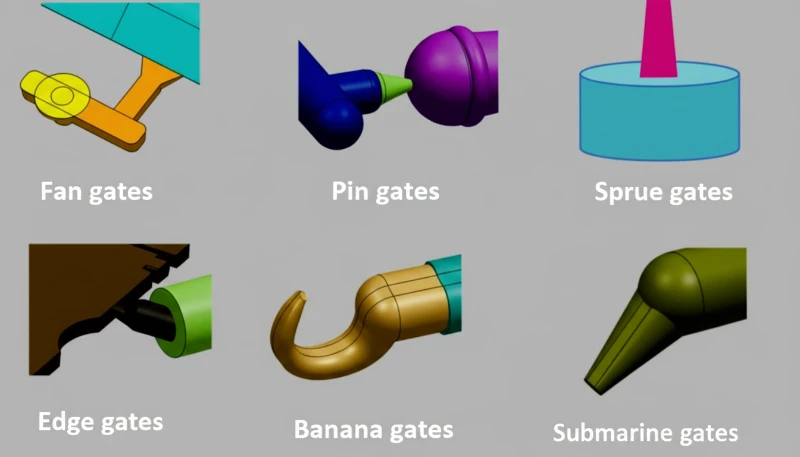
Gate location and type deserve careful consideration. The gate is where molten plastic enters the cavity, and its location determines the flow pattern, weld-line placement, and packing pressure distribution — all of which affect the final geometry. A single edge gate creates a unidirectional flow that favors parallelism along the flow direction. Multiple gates can balance filling but introduce weld lines that create weak points and geometric discontinuities.
ZetarMold’s quality team includes 10+ QC specialists who follow a 6-step inspection workflow covering IQC, in-process checks, and final OQC to verify geometric tolerance compliance on every production run.
成形部品の幾何公差はどのように測定・検査するか?
CMMs, optical scanners, and functional gauges are the three primary methods for measuring geometric tolerances on injection molded plastic parts. Each method has specific advantages depending on the tolerance type and production volume.
CMM measurement with touch probes is the standard for position, perpendicularity, and parallelism checks. However, plastic parts are compliant — probe contact force can deflect the surface, introducing measurement error. Using low-probe-force CMMs (typically under 50 mN) or non-contact laser probes minimizes this issue. For flatness measurement, optical scanning with structured light provides full-surface data rather than the sparse point sets from touch probes, giving a more accurate picture of the actual surface condition.
Functional gauging remains the most practical method for high-volume production. A go/no-go gauge that simulates the mating component provides a pass/fail result that directly correlates with assembly function. While gauges cannot tell you exactly how much geometric deviation exists, they are fast, repeatable, and require minimal operator skill — making them ideal for in-process inspection on the production floor.

射出成形部品における現実的な幾何公差範囲とは?
Geometric tolerance ranges for injection molded parts are typically between 0 and 1 mm, depending on tolerance type, material, and part geometry. The following table provides practical ranges based on industry experience and standard tolerance references for injection molding.
| Tolerance Type | Precision (Tight) | Standard (Normal) | Coarse (Loose) |
|---|---|---|---|
| Flatness (per 100 mm) | 0.05–0.10 mm | 0.10–0.30 mm | 0.30–0.60 mm |
| Straightness (per 100 mm) | 0.05–0.10 mm | 0.10–0.25 mm | 0.25–0.50 mm |
| Circularity (diameter) | 0.03–0.08 mm | 0.08–0.15 mm | 0.15–0.30 mm |
| Perpendicularity (per 100 mm) | 0.05–0.10 mm | 0.10–0.25 mm | 0.25–0.50 mm |
| Parallelism (per 100 mm) | 0.08–0.15 mm | 0.15–0.35 mm | 0.35–0.70 mm |
| Position (RFS) | Ø0.10–0.20 mm | Ø0.20–0.50 mm | Ø0.50–1.00 mm |
| 面の輪郭度 | 0.10–0.20 mm | 0.20–0.50 mm | 0.50–1.00 mm |
These ranges assume standard processing conditions with optimized 金型設計. Achieving the ‘Precision’ column typically requires specialized tooling features like conformal cooling, in-mold pressure sensors, and possibly post-mold fixturing. The ‘Standard’ column represents what a well-designed mold running on a modern injection molding machine can consistently produce. The ‘Coarse’ column is appropriate for non-critical aesthetic or structural features.
“Conformal cooling channels in the mold can improve flatness by up to 40%.”真
Conformal cooling channels follow the part contour, providing more uniform cooling that reduces thermal gradients and the resulting warpage. Studies show flatness improvements of 30-50% compared to conventional drilled channels.
“Glass-filled materials always improve dimensional stability and geometric tolerance.”偽
Glass fibers improve stiffness and reduce overall shrinkage, but they introduce anisotropic shrinkage that can worsen warpage and flatness. The fiber orientation depends on flow direction, so parallelism and flatness may actually degrade in certain orientations.
なぜ射出成形サプライヤーとは早期に幾何公差要件を協議すべきか?
The biggest geometric tolerance problems we see in our factory are not caused by bad molding — they are caused by bad specification. Designers who finalize tolerances without consulting their injection mold supplier often specify tolerances that are either unrealistically tight or poorly targeted at non-critical features. Both mistakes waste money.
Early collaboration between the design team and the molding supplier enables several critical optimizations. First, the supplier can run mold flow simulations to validate whether the specified tolerances are achievable for the given geometry and material. Second, the tooling team can optimize gate location, cooling layout, and ejection strategy to target the most critical geometric features. Third, the quality team can design inspection protocols and fixtures that focus measurement effort on the features that matter most for function.
With our in-house mold manufacturing facility supporting 100+ mold sets per month, we can iterate on tool design quickly to achieve the best possible geometric tolerance outcomes. Our ISO 9001, ISO 13485, ISO 14001, and ISO 45001 certified quality systems ensure that geometric tolerance requirements are maintained throughout production, from first article to millionth part.
厳しい幾何公差を持つ精密射出成形部品が必要ですか?
ZetarMold is a Shanghai-based manufacturer delivering precision injection molded parts with tight geometric tolerances and 20+ years of experience. Our 8 senior engineers work with you from the design stage to optimize part geometry, material selection, and tool design for the best dimensional outcomes. Whether you need flat sealing surfaces within 0.1 mm or position tolerances for precision mounting holes, our team has the expertise and equipment to deliver. Get a free quote today and let us help you specify and achieve the right geometric tolerances for your project.
射出成形における幾何公差に関するよくある質問
よくある質問
What is the difference between dimensional tolerances and geometric tolerances?
Dimensional tolerances control the allowable variation in a single linear measurement such as a length, width, or diameter expressed as a plus or minus range. Geometric tolerances by contrast control the shape orientation or spatial relationship of a feature: how flat a surface is how perpendicular two faces are or how accurately a hole is positioned relative to a datum. For injection molded parts geometric tolerances are often more critical than dimensional ones because they directly determine whether components fit together and function properly in assembly. In practice most part drawings need both types to fully communicate design intent.
Can injection molding achieve the same geometric tolerances as CNC machining?
Generally no. CNC machining can routinely hold geometric tolerances of 0.01-0.05 mm because the cutting tool directly creates the geometry with minimal material behavior variability. Injection molding involves material shrinkage warpage and process variability that make tolerances below 0.05 mm impractical for most part geometries and materials. However injection molding is far more economical for high-volume production even with slightly looser tolerances. The key is to design parts that function reliably with the geometric tolerance range that molding can consistently deliver rather than forcing molding to match machining capabilities.
How does part size affect achievable geometric tolerance?
Larger parts are harder to hold to tight geometric tolerances because shrinkage accumulates over greater distances and uneven cooling becomes more pronounced. A flatness of 0.1 mm over 50 mm is achievable for most engineering plastics but the same 0.1 mm over 300 mm is extremely difficult in semi-crystalline materials. Tolerance specifications should scale with feature size often expressed as a percentage or per-unit-length value. A practical guideline is to expect flatness capability of approximately 0.1 to 0.2 percent of the feature length for amorphous materials and 0.2 to 0.4 percent for semi-crystalline materials.
What is the most common geometric tolerance mistake on plastic part drawings?
The most common mistake is over-tolerancing: specifying geometric tolerances that are tighter than functional requirements demand. This drives up tooling cost increases scrap rate and slows inspection throughput without any benefit to the end product. The second most common mistake is incorrect datum selection where the chosen datum features are not stable accessible or functionally relevant for measurement. Both mistakes often stem from applying metal-machining tolerance practices to plastic parts without accounting for the fundamental differences in how molded parts behave dimensionally during and after production.
Does using a higher-pressure injection molding machine improve geometric tolerances?
Higher injection pressure alone does not improve geometric accuracy. Packing pressure must be carefully optimized for each part and material combination. Too little pressure causes short shots and sink marks while too much pressure causes flash over-packing and internal stresses that lead to warpage and dimensional instability. Process optimization through scientific molding principles including decoupled filling and packing stages with pressure and temperature sensors is far more effective than simply increasing machine tonnage or injection pressure without a systematic approach.
How soon after molding should you measure geometric tolerances?
For most engineering plastics you should wait at least 24 hours after molding before taking critical geometric measurements. Some semi-crystalline materials like nylon and PEEK continue to dimensionally stabilize for up to 48-72 hours due to ongoing post-crystallization and stress relaxation. Amorphous materials like polycarbonate and ABS stabilize faster but still benefit from a minimum 12 to 24 hour equilibration period. Measuring too early gives misleading results that do not reflect the part final geometry and can lead to incorrect process adjustments that actually worsen quality outcomes.
Can you use GD&T on 3D-printed injection molds for prototyping?
3D-printed molds such as those made with SLA resin or metal powder bed fusion can produce prototype parts for form and fit testing. However the geometric tolerance capability is significantly looser than production steel molds because printed molds have lower thermal conductivity less precise cavity surfaces and limited pressure resistance. Expect tolerances 3 to 5 times wider than what a hardened tool steel mold can achieve. GD&T callouts on prototype parts should be clearly marked as preliminary and re-evaluated when transitioning to production tooling made from hardened steel.
What role does mold temperature play in geometric tolerance control?
Mold temperature directly affects cooling rate crystallization behavior and residual stress formation all of which influence the final geometric accuracy of the molded part. Higher mold temperatures produce more uniform cooling and lower internal stresses which typically improves flatness and warpage control. However higher mold temperature also increases cycle time and production cost. For semi-crystalline materials mold temperature also affects the degree of crystallization which in turn affects shrinkage magnitude. Finding the optimal mold temperature is a balance between geometric quality production efficiency and cost considerations.
-
ASME Y14.5: ASME Y14.5 refers to the American national standard for geometric dimensioning and tolerancing, published by the American Society of Mechanical Engineers. ↩
-
ISO 1101: ISO 1101 refers to the international standard for geometrical product specifications (GPS) — geometrical tolerancing — tolerances of form, orientation, location and run-out. ↩
-
mold flow simulation: mold flow simulation refers to computational analysis of the injection molding process that predicts fill pattern, pressure distribution, and warpage before mold fabrication. ↩