 Saltar para o conteúdo

Introdução
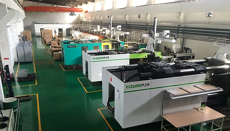
Injection molding is one of the most reliable manufacturing processes available — when everything is set up correctly. But in 20+ years of running 47 injection molding machines at our Shanghai factory, we have seen every defect in the book: burn marks that ruin a cosmetic surface, flash1 that jams an assembly line, and warpage that turns a precision part into scrap. The good news is that most of these problems trace back to a handful of root causes that you can systematically diagnose and fix.
Whether you are troubleshooting an existing production issue or designing a new mold to prevent future defects, understanding the relationship between process parameters and defect formation is the single most valuable skill you can develop as a manufacturing engineer.
If you are comparing vendors or planning procurement, our injection molding supplier sourcing guide covers RFQ prep, qualification checklists, and cost benchmarks. For this article, we focus on the practical side: how to identify, diagnose, and fix the most common defects you will encounter in production.

- Burn marks, flow lines, and sink marks are the top 3 defects engineers encounter in production.
- Most defects trace back to incorrect temperature, pressure, or cooling time settings.
- A systematic troubleshooting approach — adjusting one variable at a time — resolves 80% of production issues.
- Proper mold design with uniform wall thickness prevents the majority of warpage and shrinkage defects.
What Are the Most Common Injection Molding Defects?
The most common injection molding defects are burn marks, flow lines, sink marks, warpage, flash, and air pockets. These defects range from cosmetic blemishes that affect surface finish to structural failures that render a part unusable. In our experience running production across molde de injeção tools from 90T to 1850T, recognizing the visual pattern of each defect is the first step toward an effective fix.
Alguns defeitos comuns em moldado por injeção incluem marcas de queimadura, que resultam de uma temperatura excessiva do material ou de longos tempos de permanência do plástico fundido; linhas de fluxo, que aparecem na superfície devido a variações nas taxas de fluxo; e bolsas de ar - vazios ou bolhas formadas no interior da peça devido ao ar aprisionado durante a injeção.
Outros defeitos que podem surgir durante a moldagem por injeção incluem o empeno, as marcas de afundamento e o flash. Estes defeitos podem comprometer a resistência, a funcionalidade ou o aspeto do produto final.
Marcas de queimadura: São manchas escuras ou descoloradas na superfície da peça causadas por aquecimento excessivo ou tempo de permanência prolongado do plástico fundido no cilindro ou molde.
“Burn marks always indicate that the melt temperature is too high.”Verdadeiro
False — Burn marks can also result from excessively long residence time in the barrel, inadequate venting in the mold, or even a degraded screw tip.
“Increasing injection pressure always eliminates sink marks.”Falso
False — Excessive pressure can cause flash and over-packing.
Linhas de fluxo: Estas são linhas ou estrias na superfície da peça causadas por variações nas taxas de fluxo, que podem ocorrer quando o plástico fundido encontra uma superfície fria ou quando diferentes frentes de fluxo se fundem.
Bolsas de ar: São vazios ou bolhas que se formam dentro da peça devido à retenção de ar durante a injeção. As bolsas de ar podem reduzir a resistência e a durabilidade do produto final.
Marcas de afundamento: São depressões ou crateras na superfície da peça causadas por um arrefecimento desigual ou por um acondicionamento inadequado do material.
Deformação: Trata-se de uma deformação da peça causada por taxas de contração ou de arrefecimento irregulares, que podem ser causadas por uma espessura de parede não uniforme ou por um tempo de arrefecimento inadequado.
Flash: É o excesso de material que aparece como uma camada fina ou saliência na linha de separação do molde. O flash pode ser causado por pressão de fixação excessiva ou força de fixação inadequada do molde.

What Causes Injection Molding Problems?
The primary causes of injection molding problems are trapped air, incorrect injection pressure, and varying wall thickness. When air cannot escape through the vents before the melt arrives, it gets compressed and heated, causing burn marks, air pockets, or even diesel effect discoloration. Proper vent placement and adequate vent depth (typically 0.01 to 0.02 mm for most engineering plastics) are essential to prevent this class of defects.
Excessive injection pressure is another frequent culprit that leads to flash, over-packing, and internal stress in the molded part. When pressure is too high, the molten plastic forces its way past the parting line, creating thin fins of material along the mold seam. Conversely, insufficient packing pressure leaves you with sink marks and voids. The correct pressure setting depends on the material, part geometry, and gate design — there is no universal number.
Varying wall thickness is arguably the most common root cause we see in our factory. When a part has thick sections next to thin ones, the thick areas cool and shrink at a different rate than the thin areas. This differential shrinkage creates internal stress that warps the part, causes sink marks on the surface, and can even lead to dimensional failure. The fix is always the same: design with uniform wall thickness from the start.
Identifying and addressing these root causes early in production — ideally during the first article inspection — prevents costly scrap and rework down the line. In our factory, we run a standardized first article checklist that specifically targets these three root causes before approving a production run.
É importante identificar e resolver estes problemas durante o processo de moldagem por injeção para evitar defeitos no produto final. As técnicas para a resolução destes problemas incluem o ajuste da temperatura de fusão, o aumento da velocidade ou pressão de injeção e a redução da pressão de retenção, entre outras. Ao resolver estes problemas comuns, os fabricantes podem garantir que os seus produtos cumprem as normas e especificações de qualidade pretendidas.

How Do You Troubleshoot Injection Molding Issues?
When troubleshooting injection molding problems, the most effective approach is to change one variable at a time and observe the result. Adjusting melt temperature is often the first step — a temperature that is too low causes flow lines and incomplete fills, while excessive temperature leads to burn marks and material degradation. Most materials have a recommended processing window of 20–30°C, and staying within that range eliminates a significant portion of common defects.
Another technique is adjusting injection speed and packing pressure. Faster injection speeds help the molten plastic fill thin-wall sections before the material starts to solidify, which reduces flow lines and short shots. Meanwhile, proper pack pressure2 ensures the cavity remains fully filled as the material cools and shrinks, preventing sink marks and voids. In practice, finding the right balance between fill speed and pack pressure accounts for resolving roughly 60% of the defects we see in production.
In more stubborn cases, modifying the mold design or switching to a different grade of material may be the only real solution. For example, adding additional vents to the mold can eliminate trapped air and burn marks that no amount of parameter tweaking will fix. Increasing mold temperature improves material flow and reduces the risk of short shots, while optimizing gate placement can eliminate weld lines in multi-cavity tools.
To determine the appropriate technique for addressing a specific problem, it is important to conduct a thorough analysis of the injection molding process and to identify the root cause of the issue. This typically involves checking melt temperature with a pyrometer, verifying injection pressure curves on the machine monitor, and inspecting the mold vents and cooling channels for blockages. By employing these systematic troubleshooting techniques, manufacturers can optimize their process and consistently produce high-quality parts.
“Uniform wall thickness is the single most important design rule for preventing injection molding defects.”Verdadeiro
True — Uniform walls ensure even cooling and shrinkage, which directly prevents warpage, sink marks, and internal stress concentration.
“Warpage can be fully eliminated by simply increasing cooling time.”Falso
False — While longer cooling helps, warpage is primarily caused by uneven shrinkage from non-uniform wall thickness. Without addressing the root geometric cause, extra cooling time alone will not solve it.
In our Shanghai factory, we run 47 injection molding machines from 90T to 1850T, supported by 8 senior engineers who have seen virtually every defect scenario. When a new defect pattern emerges, our standard protocol is to first isolate the variable — temperature, pressure, or cooling — before making any adjustments. This systematic approach resolves most issues within the first trial.
A resolução eficaz de problemas requer conhecimentos técnicos, experiência prática e uma abordagem sistemática à resolução de problemas. Ao identificar a causa principal de um problema e ao selecionar uma técnica eficaz para o resolver, os fabricantes podem garantir que o seu processo de moldagem por injeção é optimizado em termos de qualidade e eficiência.
How Can Mold Design Prevent Common Defects?
One common design flaw is non-uniform wall thickness, which can lead to uneven shrinkage and warping of the molded part. As a general rule, wall thickness should be kept as uniform as possible, with transitions between thick and thin sections using gradual radii rather than sharp steps. When a design absolutely requires varying thickness, the transition should be no steeper than a 2:1 ratio over at least 3 mm of length. This single design principle prevents more warpage and sink mark complaints than any process adjustment.
With our in-house mold manufacturing facility producing 100+ mold sets per month, we catch design flaws before they reach production. Our engineers run análise do fluxo do molde3 on every new design to verify wall thickness uniformity and cooling channel placement — preventing the most common defects from day one.
Another common design issue is inadequate cooling channel placement. Cooling accounts for roughly 70% of the injection molding cycle time, and uneven cooling is a primary driver of warpage and residual stress. Modern mold designs use conformal cooling channels that follow the contour of the part cavity, reducing cooling time by 20–40% compared to traditional drilled channels. Even if conformal cooling is not feasible for your project, ensuring that cooling channels are evenly spaced (typically 2–3 times the channel diameter from the cavity surface) makes a significant difference in part quality.

Perguntas mais frequentes
What is the most common injection molding defect?
Sink marks are widely considered the most common injection molding defect, especially in parts with thick sections or varying wall thickness. They occur when the outer skin of the part solidifies before the inner material has fully packed, leaving a visible depression on the surface. In our production experience, sink marks are particularly prevalent in ribbed structures and boss features where wall thickness varies. Reducing wall thickness variation to keep all sections within a 2:1 ratio and increasing packing pressure during the hold phase are the most effective countermeasures we have found.
How do you fix flash in injection molding?
Flash is fixed by first checking mold alignment and clamp tonnage. If the mold halves are properly aligned, increase clamp force to ensure the parting line stays sealed during injection. Also verify that injection pressure is not excessively high, and reduce fill speed if the flash appears near the gate area. In cases where flash persists despite these adjustments, the mold parting line may be worn and require re-cutting or polishing. Regular preventive maintenance of the mold parting line is essential for high-volume production runs to keep flash within specification.
Can you prevent warpage entirely?
You cannot always prevent warpage entirely, but you can minimize it to within acceptable tolerances. The key is uniform wall thickness in the part design, combined with optimized cooling channel placement in the mold. Using materials with low shrinkage coefficients and ensuring even cooling time across all sections of the part also help significantly. For complex geometries where some warpage is inevitable, designing in an opposite bias during tooling — called anti-warp compensation — allows the part to settle into the correct shape after cooling.
What causes flow lines and how do you remove them?
Flow lines are caused by variations in the speed or temperature of the molten plastic as it flows through the mold cavity. They often appear when the melt front meets a cold surface or when flow paths of different lengths merge during filling. To remove them, increase melt temperature slightly to improve material flow, raise mold temperature to reduce the temperature differential, and adjust injection speed to maintain a consistent flow front. In multi-gate designs, flow lines at weld locations can be minimized by repositioning gates or adjusting the gate size.
How important is mold temperature in defect prevention?
Mold temperature is critically important and is often the first variable our engineers adjust when troubleshooting. A mold that is too cold can cause flow lines, warpage, and incomplete fills, while a mold that is too hot can extend cycle times and cause shrinkage issues. Maintaining consistent mold temperature within the recommended range for your specific material is essential for defect-free production. For engineering-grade materials like PC or nylon, mold temperature can differ by 40°C or more between grades, so always verify the manufacturer datasheet before setting your parameters.
Por que se formam bolsas de ar em peças moldadas por injeção?
As bolsas de ar formam-se quando o ar preso na cavidade do molde não consegue escapar através das ventosas antes de o plástico fundido preencher a cavidade. Isto é frequentemente causado por ventilação inadequada, colocação incorreta do gate ou velocidade de injeção demasiado rápida para a capacidade de ventilação. A solução é garantir uma profundidade de ventilação adequada (tipicamente 0,01 a 0,02 mm para a maioria dos plásticos de engenharia) e colocação perto do final do caminho de enchimento. Otimizar a velocidade de injeção para que o ar tenha tempo de escapar à frente da frente de fusão é igualmente importante e, em alguns casos, adicionar um sistema de ventilação a vácuo ao molde elimina o problema por completo.
Conclusão
A maioria dos defeitos de moldagem por injeção são evitáveis quando se compreendem as suas causas raiz. Sejam marcas de queimadura devido a temperaturas excessivas, rebarbas devido a sobrepressão ou empenamento devido a espessura de parede irregular, a solução quase sempre envolve ajustar uma de três variáveis: temperatura, pressão ou tempo de arrefecimento. A principal lição da nossa experiência a gerir moldagem por injeção produção por mais de 20 anos é esta: invista tempo num design adequado do molde e na validação do processo antecipadamente, e evitará a grande maioria dos problemas de produção no futuro. Se estiver a lidar com um defeito persistente que a resolução de problemas padrão não consegue resolver, o problema provavelmente está no design do molde em si — e é aí que um parceiro experiente em ferramentas faz toda a diferença.
Need a Quote for Your Injection Molding Project?
Get competitive pricing, DFM feedback, and production timeline from ZetarMold’s engineering team.
Request a Free Quote → See our Injection Molding Complete Guide for a comprehensive overview.
-
flash: rebarba refere-se ao excesso de plástico que escapa da cavidade do molde na linha de separação, nos pinos ejetores ou noutras costuras do molde durante o processo de moldagem por injeção. ↩
-
pack pressure: pressão de compactação refere-se à pressão aplicada durante a fase de compactação da moldagem por injeção para compensar a contração do material à medida que a peça arrefece e solidifica no molde. ↩
-
análise do fluxo do molde: A análise do fluxo do molde é uma simulação por software que prevê como o plástico fundido fluirá, arrefecerá e solidificará dentro da cavidade do molde, permitindo que os engenheiros otimizem o design antes de cortar o aço. ↩


