 Skip to content

Introduction
Injection molding is one of the most reliable manufacturing processes available — when everything is set up correctly. But in 20+ years of running 47 injection molding machines at our Shanghai factory, we have seen every defect in the book: burn marks that ruin a cosmetic surface, flash1 that jams an assembly line, and warpage that turns a precision part into scrap. The good news is that most of these problems trace back to a handful of root causes that you can systematically diagnose and fix.
Whether you are troubleshooting an existing production issue or designing a new mold to prevent future defects, understanding the relationship between process parameters and defect formation is the single most valuable skill you can develop as a manufacturing engineer.
If you are comparing vendors or planning procurement, our injection molding supplier sourcing guide covers RFQ prep, qualification checklists, and cost benchmarks. For this article, we focus on the practical side: how to identify, diagnose, and fix the most common defects you will encounter in production.

- Burn marks, flow lines, and sink marks are the top 3 defects engineers encounter in production.
- Most defects trace back to incorrect temperature, pressure, or cooling time settings.
- A systematic troubleshooting approach — adjusting one variable at a time — resolves 80% of production issues.
- Proper mold design with uniform wall thickness prevents the majority of warpage and shrinkage defects.
What Are the Most Common Injection Molding Defects?
The most common injection molding defects are burn marks, flow lines, sink marks, warpage, flash, and air pockets. These defects range from cosmetic blemishes that affect surface finish to structural failures that render a part unusable. In our experience running production across injection mold tools from 90T to 1850T, recognizing the visual pattern of each defect is the first step toward an effective fix.
Some common defects in injection molded include burn marks, which result from excessive material temperature or long residence times of the molten plastic; flow lines, which appear on the surface due to variations in flow rates; and air pockets – voids or bubbles formed within the part due to trapped air during the injection.
Other defects that can arise during injection molding include warping, sink marks, and flash. These flaws may compromise a product’s strength, functionality, or appearance in the final product.
Burn marks: These are dark or discolored spots on the surface of the part caused by excessive heating or prolonged residence time of the molten plastic in the barrel or mold.
“Burn marks always indicate that the melt temperature is too high.”True
False — Burn marks can also result from excessively long residence time in the barrel, inadequate venting in the mold, or even a degraded screw tip.
“Increasing injection pressure always eliminates sink marks.”False
False — Excessive pressure can cause flash and over-packing.
Flow lines: These are lines or streaks on the surface of the part caused by variations in flow rates, which can occur when molten plastic meets a cold surface or when different flow fronts merge.
Air pockets: These are voids or bubbles that form within the part due to trapped air during the injection. Air pockets can reduce the strength and durability of the final product.
Sink marks: These are depressions or craters on the surface of the part caused by uneven cooling or inadequate packing of the material.
Warping: This is a deformation of the part caused by uneven shrinkage or cooling rates, which can be caused by non-uniform wall thickness or inadequate cooling time.
Flash: This is excess material that appears as a thin layer or protrusion on the parting line of the mold. Flash can be caused by excessive clamp pressure or inadequate mold clamping force.

What Causes Injection Molding Problems?
The primary causes of injection molding problems are trapped air, incorrect injection pressure, and varying wall thickness. When air cannot escape through the vents before the melt arrives, it gets compressed and heated, causing burn marks, air pockets, or even diesel effect discoloration. Proper vent placement and adequate vent depth (typically 0.01 to 0.02 mm for most engineering plastics) are essential to prevent this class of defects.
Excessive injection pressure is another frequent culprit that leads to flash, over-packing, and internal stress in the molded part. When pressure is too high, the molten plastic forces its way past the parting line, creating thin fins of material along the mold seam. Conversely, insufficient packing pressure leaves you with sink marks and voids. The correct pressure setting depends on the material, part geometry, and gate design — there is no universal number.
Varying wall thickness is arguably the most common root cause we see in our factory. When a part has thick sections next to thin ones, the thick areas cool and shrink at a different rate than the thin areas. This differential shrinkage creates internal stress that warps the part, causes sink marks on the surface, and can even lead to dimensional failure. The fix is always the same: design with uniform wall thickness from the start.
Identifying and addressing these root causes early in production — ideally during the first article inspection — prevents costly scrap and rework down the line. In our factory, we run a standardized first article checklist that specifically targets these three root causes before approving a production run.
It is important to identify and address these problems during the injection molding process to prevent defects in the final product. Techniques for troubleshooting these problems include adjusting melt temperature, increasing injection speed or pressure, and reducing hold pressure, among others. By addressing these common problems, manufacturers can ensure that their products meet the desired quality standards and specifications.

How Do You Troubleshoot Injection Molding Issues?
When troubleshooting injection molding problems, the most effective approach is to change one variable at a time and observe the result. Adjusting melt temperature is often the first step — a temperature that is too low causes flow lines and incomplete fills, while excessive temperature leads to burn marks and material degradation. Most materials have a recommended processing window of 20–30°C, and staying within that range eliminates a significant portion of common defects.
Another technique is adjusting injection speed and packing pressure. Faster injection speeds help the molten plastic fill thin-wall sections before the material starts to solidify, which reduces flow lines and short shots. Meanwhile, proper pack pressure2 ensures the cavity remains fully filled as the material cools and shrinks, preventing sink marks and voids. In practice, finding the right balance between fill speed and pack pressure accounts for resolving roughly 60% of the defects we see in production.
In more stubborn cases, modifying the mold design or switching to a different grade of material may be the only real solution. For example, adding additional vents to the mold can eliminate trapped air and burn marks that no amount of parameter tweaking will fix. Increasing mold temperature improves material flow and reduces the risk of short shots, while optimizing gate placement can eliminate weld lines in multi-cavity tools.
To determine the appropriate technique for addressing a specific problem, it is important to conduct a thorough analysis of the injection molding process and to identify the root cause of the issue. This typically involves checking melt temperature with a pyrometer, verifying injection pressure curves on the machine monitor, and inspecting the mold vents and cooling channels for blockages. By employing these systematic troubleshooting techniques, manufacturers can optimize their process and consistently produce high-quality parts.
“Uniform wall thickness is the single most important design rule for preventing injection molding defects.”True
True — Uniform walls ensure even cooling and shrinkage, which directly prevents warpage, sink marks, and internal stress concentration.
“Warpage can be fully eliminated by simply increasing cooling time.”False
False — While longer cooling helps, warpage is primarily caused by uneven shrinkage from non-uniform wall thickness. Without addressing the root geometric cause, extra cooling time alone will not solve it.
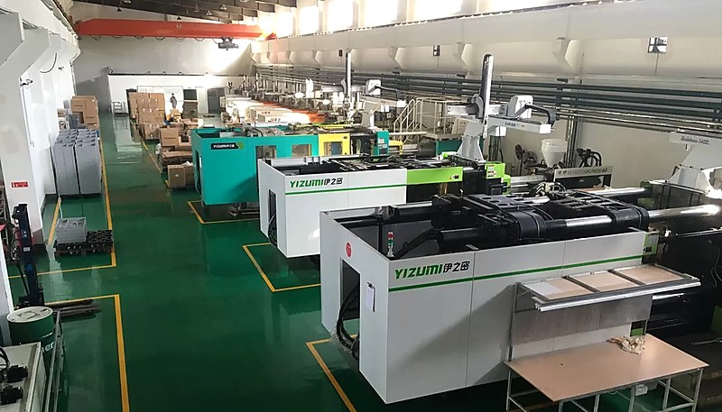
In our Shanghai factory, we run 47 injection molding machines from 90T to 1850T, supported by 8 senior engineers who have seen virtually every defect scenario. When a new defect pattern emerges, our standard protocol is to first isolate the variable — temperature, pressure, or cooling — before making any adjustments. This systematic approach resolves most issues within the first trial.
Effective troubleshooting requires technical knowledge, practical experience, and a systematic approach to problem-solving. By pinpointing the root cause of an issue and selecting an effective technique for fixing it, manufacturers can guarantee their injection molding process is optimized for quality and efficiency.
How Can Mold Design Prevent Common Defects?
One common design flaw is non-uniform wall thickness, which can lead to uneven shrinkage and warping of the molded part. As a general rule, wall thickness should be kept as uniform as possible, with transitions between thick and thin sections using gradual radii rather than sharp steps. When a design absolutely requires varying thickness, the transition should be no steeper than a 2:1 ratio over at least 3 mm of length. This single design principle prevents more warpage and sink mark complaints than any process adjustment.
With our in-house mold manufacturing facility producing 100+ mold sets per month, we catch design flaws before they reach production. Our engineers run mold flow analysis3 on every new design to verify wall thickness uniformity and cooling channel placement — preventing the most common defects from day one.
Another common design issue is inadequate cooling channel placement. Cooling accounts for roughly 70% of the injection molding cycle time, and uneven cooling is a primary driver of warpage and residual stress. Modern mold designs use conformal cooling channels that follow the contour of the part cavity, reducing cooling time by 20–40% compared to traditional drilled channels. Even if conformal cooling is not feasible for your project, ensuring that cooling channels are evenly spaced (typically 2–3 times the channel diameter from the cavity surface) makes a significant difference in part quality.

Frequently Asked Questions
What is the most common injection molding defect?
Sink marks are widely considered the most common injection molding defect, especially in parts with thick sections or varying wall thickness. They occur when the outer skin of the part solidifies before the inner material has fully packed, leaving a visible depression on the surface. In our production experience, sink marks are particularly prevalent in ribbed structures and boss features where wall thickness varies. Reducing wall thickness variation to keep all sections within a 2:1 ratio and increasing packing pressure during the hold phase are the most effective countermeasures we have found.
How do you fix flash in injection molding?
Flash is fixed by first checking mold alignment and clamp tonnage. If the mold halves are properly aligned, increase clamp force to ensure the parting line stays sealed during injection. Also verify that injection pressure is not excessively high, and reduce fill speed if the flash appears near the gate area. In cases where flash persists despite these adjustments, the mold parting line may be worn and require re-cutting or polishing. Regular preventive maintenance of the mold parting line is essential for high-volume production runs to keep flash within specification.
Can you prevent warpage entirely?
You cannot always prevent warpage entirely, but you can minimize it to within acceptable tolerances. The key is uniform wall thickness in the part design, combined with optimized cooling channel placement in the mold. Using materials with low shrinkage coefficients and ensuring even cooling time across all sections of the part also help significantly. For complex geometries where some warpage is inevitable, designing in an opposite bias during tooling — called anti-warp compensation — allows the part to settle into the correct shape after cooling.
What causes flow lines and how do you remove them?
Flow lines are caused by variations in the speed or temperature of the molten plastic as it flows through the mold cavity. They often appear when the melt front meets a cold surface or when flow paths of different lengths merge during filling. To remove them, increase melt temperature slightly to improve material flow, raise mold temperature to reduce the temperature differential, and adjust injection speed to maintain a consistent flow front. In multi-gate designs, flow lines at weld locations can be minimized by repositioning gates or adjusting the gate size.
How important is mold temperature in defect prevention?
Mold temperature is critically important and is often the first variable our engineers adjust when troubleshooting. A mold that is too cold can cause flow lines, warpage, and incomplete fills, while a mold that is too hot can extend cycle times and cause shrinkage issues. Maintaining consistent mold temperature within the recommended range for your specific material is essential for defect-free production. For engineering-grade materials like PC or nylon, mold temperature can differ by 40°C or more between grades, so always verify the manufacturer datasheet before setting your parameters.
Why do air pockets form in injection molded parts?
Air pockets form when air trapped in the mold cavity cannot escape through the vents before the molten plastic fills the cavity. This is often caused by inadequate venting, incorrect gate placement, or injection speed that is too fast for the vent capacity. The solution is to ensure proper vent depth (typically 0.01 to 0.02 mm for most engineering plastics) and placement near the end of the fill path. Optimizing injection speed so the air has time to escape ahead of the melt front is equally important, and in some cases, adding a vacuum venting system to the mold eliminates the problem entirely.
Conclusion
Most injection molding defects are preventable when you understand their root causes. Whether it is burn marks from excessive temperatures, flash from over-pressure, or warpage from uneven wall thickness, the solution almost always involves adjusting one of three variables: temperature, pressure, or cooling time. The key takeaway from our experience running injection molding production for over 20 years is this: invest time in proper mold design and process validation upfront, and you will avoid the vast majority of production headaches down the line. If you are dealing with a persistent defect that standard troubleshooting cannot resolve, the problem likely lies in the mold design itself — and that is where an experienced tooling partner makes all the difference.
Need a Quote for Your Injection Molding Project?
Get competitive pricing, DFM feedback, and production timeline from ZetarMold’s engineering team.
Request a Free Quote → See our Injection Molding Complete Guide for a comprehensive overview.
-
flash: flash refers to is the excess plastic that escapes from the mold cavity at the parting line, ejector pins, or other mold seams during the injection molding process. ↩
-
pack pressure: pack pressure refers to is the pressure applied during the packing phase of injection molding to compensate for material shrinkage as the part cools and solidifies in the mold. ↩
-
mold flow analysis: Mold flow analysis is a software simulation that predicts how molten plastic will flow, cool, and solidify within a mold cavity, allowing engineers to optimize design before cutting steel. ↩


