 Przejdź do treści

If you have spent any time around injection molding, you have heard the terms sprue1, runner2oraz brama3 tossed around like they mean the same thing. They do not. Getting these confused can lead to bad mold design, wasted material, and parts that never fill correctly.
After 20+ years of building molds and running production in our Shanghai factory, we have seen every runner-system mistake in the book. This article breaks down exactly what each component does, how they differ, and which design choices actually matter on the shop floor.
- The sprue is the first vertical channel from the machine nozzle into the mold.
- Runners distribute melt horizontally from the sprue to individual cavity gates.
- Gates are the narrowest point — they control flow, freeze-off, and part separation.
- Cold runner systems produce waste; hot runner systems eliminate it but cost more upfront.
- Gate type selection directly affects part quality, cycle time, and post-processing labor.
What Is a Sprue in Injection Molding?
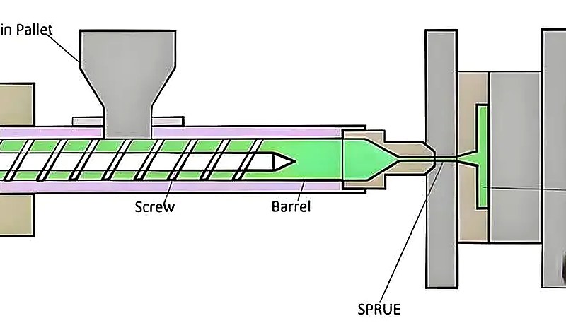
A sprue is the first and largest channel in the feed system. It starts at the machine nozzle, passes through the mold top plate, and connects to the runner network. Think of it as the main supply line — everything flows through here first.
In a typical two-plate mold, the sprue is a tapered (conical) hole bored through the sprue bushing. The taper — usually 1 to 3 degrees per side — exists so the solidified sprue can be ejected cleanly. A straight-walled sprue would stick and jam the mold every cycle.
Key dimensions matter. The sprue’s large-end diameter at the nozzle interface typically matches or slightly exceeds the machine nozzle orifice (3–6 mm for most general-purpose molding). The small end feeds into the runner. If the sprue is too narrow, you get excessive pressure drop right at the start of fill. Too wide, and you waste material and extend cooling time.
In our Shanghai factory, ZetarMold has 20+ years of injection molding and tooling experience, runs 47 injection molding machines from 90T to 1850T, and supports projects with in-house tooling. For sprue and runner design, this matters because the same mold can behave differently when it moves from trial press to production press.
What Is a Runner in Injection Molding?
A runner is the horizontal channel network that routes molten plastic from the bottom of the sprue to each cavity gate. In a multi-cavity formowanie wtryskowe mold, the runner system is the distribution backbone — it determines whether every cavity fills at the same time and pressure, or whether you get short shots in some cavities and over-packed flash in others.
Runners come in several cross-sectional profiles. The most common are:
Full-round — Circular cross-section. Best surface-area-to-volume ratio, meaning the least heat loss and lowest pressure drop. Requires machining on both mold halves, so tooling cost is higher.
Trapezoidal — Machined into one mold half only. Easier and cheaper to cut. The compromise is slightly more heat loss and pressure drag.
Modified trapezoidal (U-shape) — A hybrid that improves on the standard trapezoid with rounded corners, giving better flow characteristics while staying machinable on one side.
Runner diameter typically ranges from 3 mm to 10 mm depending on part size, material viscosity, and flow length. In our shop, we rarely go below 4 mm for anything beyond tiny micro-molding — below that, the pressure losses stack up fast, especially with high-viscosity engineering plastics.
“The runner diameter in most production molds ranges from 3 mm to 10 mm.”Prawda
True. This is the standard range. Smaller runners create excessive pressure loss, while larger runners waste material and extend cycle time.
“Runners are always machined on both halves of the mold.”Fałsz
False. Trapezoidal and U-shaped runners are machined on only one mold half. Only full-round runners require machining on both sides.
What Is a Gate and How Does It Differ from Sprue and Runner?
A gate is the narrowest constriction between the runner and the mold cavity. It is the last door the plastic passes through before entering the cavity. Gates serve four critical functions that directly determine part quality and production efficiency.
1. Flow control. The gate restricts and directs the melt. A smaller gate increases shear rate, which heats the material through viscous friction and temporarily lowers viscosity — helping fill thin sections.
2. Freeze-off seal. Once the cavity is packed, the gate is the first thing to solidify. This seals the cavity so packed material cannot flow backward into the runner when injection pressure drops.
3. Separation point. After ejection, the gate is where the part separates from the runner system. A well-designed gate snaps clean or requires minimal trimming.
4. Packing control. Gate size and freeze time directly control how much packing material enters the cavity.
Too large a gate means long packing — and possible over-packing, flash, or high residual stress. Too small, and the gate freezes before the cavity is fully packed, causing sink marks or voids.
What Is the Complete Feed Path from Nozzle to Cavity?
The complete feed path from nozzle to cavity is defined by the function, constraints, and tradeoffs explained in this section. The full journey of molten plastic through an forma wtryskowa follows this sequence: Machine barrel → Nozzle tip → Sprue (vertical, through top clamp plate) → Runner (horizontal, through parting surface) → Gate (narrow constriction) → Cavity.
Each stage is a step down in cross-section. The sprue is the largest channel, the runner is smaller and branched, and the gate is the smallest constriction. This tapering is deliberate — it maintains flow velocity and pressure right up to the cavity entrance.
There is also a cold slug well at the base of the sprue, opposite the sprue puller. Its job is to catch the cold, slow-moving slug of plastic that sits at the nozzle tip between cycles. Without it, that cold plug would travel down the runner and potentially block a gate or cause a visible blemish on the part.
“The cold slug well catches solidified plastic from the nozzle tip between cycles.”Prawda
True. Without a cold slug well, the solidified nozzle tip material would enter the runner system and could block a gate or create surface defects on the molded part.
“The gate is the largest channel in the feed system.”Fałsz
False. The gate is the smallest constriction. The sprue is the largest channel, the runner is medium, and the gate is the narrowest point between the runner and the cavity.
Which system should you use: cold runner or hot runner?
This is one of the most consequential design decisions in any mold build. The runner system type affects material waste, cycle time, part quality, and tooling cost. Understanding the trade-offs helps you make the right call for your production volume and budget.
A cold runner system is the traditional, lower-cost approach. The runner channels are unheated — they are simply machined into the mold steel. After each cycle, the runner plastic solidifies along with the parts and is ejected. That solidified runner is waste (or regrind), typically 5–30% of total shot weight depending on part geometry.
A hot runner system uses cartridge heaters, thermocouples, and manifold blocks to keep the plastic inside the runner channels molten at all times. No runner waste is ejected — only the parts. This saves material, reduces cycle time (no runner to cool and eject), and often enables faster color or material changes. The trade-off is significantly higher tooling cost and maintenance complexity.
Here is a practical comparison:
| Kryteria | Cold Runner | Hot Runner |
|---|---|---|
| Koszt oprzyrządowania | Lower ($3K–$15K less) | Higher (heated manifold + controllers) |
| Odpady materiałowe | 5–30% per shot (runner scrap) | Near zero (no solidified runner) |
| Czas cyklu | Longer (runner must cool) | Shorter (no runner cooling needed) |
| Konserwacja | Simple, robust | Complex (heaters, thermocouples, leaks) |
| Color Change | Easy (purge entire system) | Slower (residual melt in manifold) |
| Part Quality | Gate marks, possible vestige | Cleaner gates, thermal gate or valve |
| Najlepsze dla | Mało-średnia seria, częste zmiany koloru | High volume, tight tolerance, expensive resins |
{“type”:”factory_insight”,”fact_ids”:[“equipment.injection_machines_47″,”equipment.tonnage_90_1850″],”text”:”In our Shanghai facility, we run 47 injection molding machines from 90T to 1850T, producing parts with both cold and hot runner molds. For medical and high-volume consumer electronics work, hot runners almost always win on total cost of ownership once you exceed about 100,000 cycles.”}
What Are the Most Common Gate Types?
The most common gate types are the main categories or options explained in this section. Gate selection is not a theoretical exercise — it directly determines whether your part fills cleanly, how much post-processing it needs, and whether automated production is even possible. Here are the six gate types you will encounter most often in production tooling:
1. Direct (sprue) gate. The simplest gate — the sprue feeds directly into the cavity with no runner. Used for single-cavity molds making large, thick-walled parts like buckets or housings. Low pressure loss, but leaves a large, visible gate mark and cannot be used for multi-cavity layouts.
2. Edge (side) gate. The most versatile gate type, located on the parting surface at the edge of the cavity. Easy to machine, easy to adjust dimensions, and works with most materials. The downsides are visible gate vestige and the need for manual degating.
3. Submarine (tunnel) gate. The runner channel angles below the parting line and enters the cavity from the underside or an interior surface. When the mold opens, the angled runner automatically shears the gate from the part — enabling fully automated production with no visible gate mark on the cosmetic surface. Not recommended for brittle materials like PC or PMMA.
“Submarine gates can enable fully automated production because the gate shears off during mold opening.”Prawda
True. The angled tunnel design causes the gate to self-sever from the part as the mold opens, eliminating the need for manual degating.
“Pin-point gates work with standard two-plate molds.”Fałsz
False. Pin-point gates require a three-plate mold (double parting surface) because the gate must be stripped from the fixed side during mold opening. Standard two-plate molds cannot accommodate this gate type.
4. Pin-point gate. A very small-diameter gate (typically 0.5–1.5 mm) that leaves minimal vestige and self-severs during ejection. Requires a three-plate mold. High injection pressure loss, but excellent for cosmetic parts and multi-cavity tools.
5. Fan gate. A wide, flat gate that spreads the melt across a broad front. Ideal for thin-walled parts where you need to avoid jetting or high-shear defects. Common in flat panels and lens covers.
6. Valve gate (hot runner only). A mechanically actuated pin that opens and closes the gate orifice. Provides the cleanest gate mark, precise control over gate-open timing, and is used in high-end multi-cavity and sequential-fill applications. The most expensive option.

How Does Gate Size Affect Part Quality?
Gate size is the control point for fill speed, packing time, and separation quality. If it is wrong, defects show up quickly.
Gate too small: High shear rate through the gate causes excessive frictional heating, which can degrade temperature-sensitive resins. The gate also freezes too early, cutting off packing pressure before the cavity is fully compensated for shrinkage. Result: sink marks, voids, and under-packed parts. You also see high pressure drops that may cause short shots in multi-cavity tools.
Gate too large: Extended packing time, over-packing near the gate, and high residual stress. The gate vestige is larger and harder to remove cleanly. Cycle time increases because the thick gate section takes longer to solidify.
In practice, we start with a gate cross-sectional area roughly 50–70% of the thinnest wall section of the part, then adjust based on mold flow simulation results. Gate land length (the straight section) is kept short — typically 0.5–1.5 mm — to minimize pressure loss. Anything longer is usually wasted pressure.
What Problems Occur When the Runner System Is Poorly Designed?
A poorly designed runner system is a direct cause of unbalanced filling, pressure loss, cold slugs, and wasted resin. In our factory, we diagnose these problems by following the melt path from nozzle to cavity before changing machine settings.
Unbalanced fill in multi-cavity molds. When runner lengths or diameters vary, some cavities fill first and others lag. The early-filling cavities get over-packed while late-fill cavities are short. The fix is balanced runner design — equal flow length and cross-section to every cavity, or flow-length compensation using different runner diameters.
Excessive pressure drop. Long, narrow runners with too many turns bleed off injection pressure before the melt reaches the cavity. If you need 120 MPa at the cavity but lose 80 MPa in the runner system, you need a bigger machine — or a better runner layout.
Cold slugs entering the cavity. If the cold slug well is missing or undersized, the solidified plug from the nozzle tip travels into the runner and blocks a gate. This shows up as intermittent short shots or surface blemishes that appear randomly.
Excessive runner waste. In cold runner molds, oversized runners (a common safety margin) waste material. In high-volume production with expensive engineering resins (PEEK, PPS, LCP), even a few grams per shot add up to thousands of dollars per year.
How Do You Optimize Runner Design for Multi-Cavity Molds?
Multi-cavity mold optimization is where experienced tool designers earn their keep. The goal is simple: every cavity fills at the same rate, at the same pressure, producing identical parts. Achieving it requires attention to three factors.
Geometric balance (naturally balanced runner). Lay out the runner so that the flow path from the sprue to every cavity has identical length, number of turns, and cross-section. An H-pattern or radial layout achieves this naturally. This is the gold standard, but it does not always fit within mold base constraints or part layout requirements.
Flow-length compensation (artificially balanced runner). When geometric balance is impossible, adjust runner diameters to equalize the pressure drop to each cavity. A cavity that is farther from the sprue gets a wider runner to compensate for the extra friction loss. This requires accurate mold flow simulation.
Gate sizing as a final trim. Even with balanced runners, small variations in cavity geometry (different part weights, wall thicknesses) can cause imbalance. Slightly adjusting individual gate sizes is the final tuning step. This is done during mold sampling — we mold test shots, measure cavity weights, and adjust gates in 0.1 mm increments.
{“type”:”factory_insight”,”fact_ids”:[“facility.in_house_mold_manufacturing”,”company.experience_20_years”],”text”:”With our in-house mold manufacturing facility and 20+ years of tooling experience, we routinely design and tune multi-cavity molds up to 64 cavities for high-volume connector and medical components.”}
“In a naturally balanced runner system, every cavity has an identical flow path from the sprue.”Prawda
Prawda. Geometrycznie zrównoważone kanały dolotowe wykorzystują układy w kształcie litery H lub promieniowe, aby zapewnić równą długość przepływu, liczbę zakrętów i przekrój do każdego gniazda, co daje spójne wypraski.
„Balansowanie układ wlewowego jest potrzebne tylko dla form z więcej niż 16 wnękami.”Fałsz
Fałsz. Nawet forma dwugniazdowa może cierpieć na nierównowagę napełniania, jeśli długości kanałów dolotowych są różne. Równoważenie kanałów jest ważne dla każdej formy wielogniazdowej, niezależnie od liczby gniazd.
What are the key differences between sprue, runner, and gate?
Jeśli potrzebujesz szybkiego porównania, ta tabela podsumowuje kluczowe różnice między wlewem, kanałem rozdzielającym i gate:
| Cecha | Wlew | Biegacz | Brama |
|---|---|---|---|
| Lokalizacja | Pionowa, przez płytę górną | Pozioma, na powierzchni rozdzielenia | Między kanałem dolotowym a gniazdem |
| Funkcja | Łączy dyszę wtryskarki z systemem kanałów dolotowych | Rozdziela stop do wszystkich gniazd | Kontroluje dopływ do gniazda |
| Rozmiar | Największy kanał (średnica 3–10 mm) | Średni (średnica 3–8 mm) | Najmniejsza (średnica 0,3–3 mm) |
| Cross-section | Stożkowy, zwężający się | Okrągły, trapezowy lub w kształcie litery U | Wąski prostokątny lub okrągły |
| Zastyga | Pierwszy otrzymuje materiał, wolno zamarza | Zamarza wraz z częścią | Pierwsza sekcja, która krzepnie |
| Wyrzut | Wyciągany przez wyciągacz wlewu / podcięcie | Wyrzucany wraz z częścią na linii rozdzielania | Odcięcie od części podczas wyciągania |
| Wskazówka projektowa | Stożek 1–3° na stronę dla czystego uwolnienia | Pełny okrągły jest najbardziej efektywny | Najmniejszy wlew, który wypełnia część |
Często zadawane pytania
Jaka jest różnica między wlewem a kanałem zasilającym?
Wlew jest pionowym kanalem łączącym wylot maszyny wtryskowej z systemem wlewowym formy, a układ wlewowy jest poziomym kanalem rozprowadzającym materiał z wlewu do indywidualnych wlewów wnęk. Wlew jest pierwszym kanalem, który plastik napotyka po końcu wylotu, przechodząc przez górną płytę zaciskową formy. Układ wlewowy występuje po wlewie i rozgałęzia się, aby dotrzeć do każdej wnęki. W zakresie wielkości, wlew jest zazwyczaj największym pojedynczym kanalem w systemie doprowadzania, a układ wlewowy jest rozgałęziony i nieco mniejszy w przekroju.
Czy Forma Może Działać Bez Lejka?
Tylko w formach gorących z bezpośrednim połączeniem wylotu z manifoldem, gdzie podgrzewany wylot doprowadza materiał bezpośrednio do manifoldu bez tradycyjnej tulei wlewowej. W większości standardowych dwupłytowych form z zimnym układem wlewowym, wlew jest niezbędny, ponieważ stanowi połączenie między stałym wylotem maszyny na części stałej i systemem wlewowym ruchomej części formy. Bez tego nie istnieje szczelny kanal transportujący materiał z cylindra maszyny do wnęk formy. Gorące układ wlewowe mogą całkowicie eliminować wlew poprzez zastosowanie podgrzewanej tulei wlewowej lub bezpośredniego wlewania.
Dlaczego wlew w formach wtryskowych jest stożkowy?
Stożkowość (1–3 stopnie na bok) tworzy kąt odbioru, który umożliwia czyste uwolnienie zestalonego ślimu z tulei ślimowej podczas otwierania formy. Prosty, cylindryczny kanał chwytałby powierzchnię stali przez tarcie i skurcz termiczny, blokując system wyciągania i potencjalnie uszkadzając powierzchnię formy w kolejnych cyklach. Stożkowość zapewnia, że ślim jest wyciągany z tulei płynnie w każdym cyklu, co jest kluczowe dla niezawodnej produkcji zautomatyzowanej, spójnych czasów cyklu i długiej żywotności formy.
Co Się Dzieje, Jeśli Biegacz Jest Zbyt Mały?
Zbyt mały kanał dolotowy powoduje nadmierny spadek ciśnienia między dyszą wtryskarki a gniazdem, co może prowadzić do niedolewania, wysokich wymagań dotyczących ciśnienia napełniania oraz zwiększonego nagrzewania ścinaniem w stopie. Maszyna może potrzebować pracy na granicy maksymalnego ciśnienia, nie pozostawiając marginesu na regulację procesu lub zmiany lepkości materiału podczas produkcji. W formach wielogniazdowych zbyt małe kanały dolotowe znacznie utrudniają również zrównoważenie napełniania gniazd, prowadząc do niespójnej jakości wyprasek, zróżnicowania wymiarowego między gniazdami oraz wyższych ogólnych wskaźników braków.
Czy Każda Forma Potrzebuje Studzienki Zimnego Ślizgu?
W formach z zimnymi kanałami — tak — zbiera on zestaloną grudkę z końcówki dyszy, która tworzy się między cyklami wtrysku. Bez niego ta zimna grudka przemieszcza się do systemu kanałów dolotowych i może zablokować śluzę lub stworzyć widoczną wadę na powierzchni gotowej wypraski. W formach z gorącymi kanałami stop pozostaje w stanie ciekłym w ogrzewanej rozdzielnicy przez cały czas, więc studzienki na zimną grudkę nie są potrzebne, ponieważ nie ma zestalonego materiału do uwięzienia. Jednak większość form z zimnymi kanałami powinna zawsze zawierać odpowiednio wymiarowaną studzienkę na zimną grudkę u podstawy ślima.
Jak Wybrać Pomiędzy Systemami Zimnego i Gorącego Rozpływu?
Używaj systemów z zimnymi kanałami do produkcji mało- i średnioseryjnej, w zastosowaniach wymagających częstych zmian koloru lub gdy budżet na narzędzie jest ograniczony. Przejdź na gorące kanały do produkcji wielkoseryjnej (zwykle powyżej 100 000 cykli), przy drogich żywicach inżynierskich, gdzie odpad z kanałów jest kosztowny, lub gdy redukcja czasu cyklu jest kluczowa dla rentowności. Większość form produkcyjnych wytwarzających ponad 500 000 części rocznie używa systemów z gorącymi kanałami, ponieważ oszczędność materiału i szybsze cykle rekompensują wyższą początkową inwestycję w narzędzie już w pierwszej serii produkcyjnej. Przed wyborem wykonaj kalkulację. Porównaj roczną wielkość produkcji, wagę kanałów, cenę żywicy, częstotliwość zmian koloru, wymaganą automatyzację, budżet na narzędzie i umiejętności serwisowe. System z gorącymi kanałami może być dobrą inwestycją, ale tylko wtedy, gdy oszczędności produkcyjne są większe niż dodana złożoność.
Czym jest balansowanie runnerów i dlaczego ma znaczenie?
Równoważenie kanałów dolotowych zapewnia, że wszystkie gniazda w formie wielogniazdowej napełniają się jednocześnie i pod równym ciśnieniem, produkując spójne wypraski ze wszystkich gniazd w każdym cyklu. Osiąga się to poprzez układ geometryczny (równe drogi przepływu przy użyciu układów kanałów w kształcie litery H lub promieniowych) lub przez regulację średnic poszczególnych kanałów w celu skompensowania różnych długości przepływu do każdego gniazda. Nierównoważone kanały powodują, że niektóre gniazda są przepełniane (co skutkuje nadlewkami, wysokimi naprężeniami własnymi i problemami wymiarowymi), podczas gdy inne są niedolewane (niedolewy, zapadnięcia i puste przestrzenie), prowadząc do niespójnej jakości wyprasek i wyższych wskaźników braków.
Który Typ Bramy Pozostawia Najmniejszy Ślad na Części?
Wlewy punktowe i podwodne (tunelowe) pozostawiają najmniejszy widoczny ślad na powierzchni części, zazwyczaj punkt lub małe zagłębienie o średnicy poniżej 1 mm. Wlewy zamykane w gorących układach wlewowych pozostawiają najczystszy ślad ze wszystkich – mały okrągły znak bez wypukłości, ponieważ trzpień zamykający odcinają wlew równo z powierzchnią części podczas zamknięcia. Bezpośrednie wlewy i duże wlewy brzegowe pozostawiają najbardziej widoczne ślady na formowanej części, które często wymagają dodatkowych operacji: przycinania, szlifowania lub wykończenia kosmetycznego przed wysyłką części.
Jak ZetarMold może pomóc w projektowaniu formy?
Wybór właściwej konfiguracji wlewu, układu wlewowego i wlewu nie jest zadaniem z podręcznika – zależy od geometrii części, materiału, wielkości produkcji i wymagań dotyczących jakości. W ZetarMold projektujemy i budujemy formy we własnym zakresie, korzystając z 47 maszyn do wtrysku (90T–1850T) i doświadczenia z ponad 400 materiałami plastikowych. Jeśli szukasz dostawca form wtryskowych, nasz zespoł inżynierów może prowadzić Cię od DFM przez produkcję.
Niezależnie od tego, czy potrzebujesz prostą formę z zimnym układ wlewowym dla krótkiej serii, czy precyzyjny gorący układ wlewowy dla produkcji milionowych części, nasz zespoł może pomóc Ci osiągnąć sukces od pierwszego podejścia.
Zamów bezpłatną ofertę → Przesłać model 3D i otrzymasz informacje DFM, zalecenia dotyczące projektu formy oraz harmonogram produkcji w ciągu 48 godzin.
-
sprue: wlew odnosi się do głównego pionowego kanału, który transportuje stopiony plastik z dyszy maszyny do wtryskiwania do systemu kanałów rozdzielających formy. ↩
-
kanał dolotowy: układ wlewowy odnosi się do układu wlewowego, który jest poziomym systemem kanalów rozprowadzającym gorący plastik z wlewu do indywidualnych wlewów wnęk w formie wielownękowej lub wielowlewowej. ↩
-
gate: wlew odnosi się do wąskiego otwarcia między układ wlewowym i wnęką formy, gdzie gorący plastik wchodzi w geometrię części. ↩


