 Ir al contenido

If you have spent any time around injection molding, you have heard the terms sprue1, runner2y puerta3 tossed around like they mean the same thing. They do not. Getting these confused can lead to bad mold design, wasted material, and parts that never fill correctly.
After 20+ years of building molds and running production in our Shanghai factory, we have seen every runner-system mistake in the book. This article breaks down exactly what each component does, how they differ, and which design choices actually matter on the shop floor.
- The sprue is the first vertical channel from the machine nozzle into the mold.
- Runners distribute melt horizontally from the sprue to individual cavity gates.
- Gates are the narrowest point — they control flow, freeze-off, and part separation.
- Cold runner systems produce waste; hot runner systems eliminate it but cost more upfront.
- Gate type selection directly affects part quality, cycle time, and post-processing labor.
What Is a Sprue in Injection Molding?
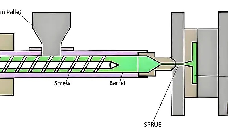
A sprue is the first and largest channel in the feed system. It starts at the machine nozzle, passes through the mold top plate, and connects to the runner network. Think of it as the main supply line — everything flows through here first.
In a typical two-plate mold, the sprue is a tapered (conical) hole bored through the sprue bushing. The taper — usually 1 to 3 degrees per side — exists so the solidified sprue can be ejected cleanly. A straight-walled sprue would stick and jam the mold every cycle.
Key dimensions matter. The sprue’s large-end diameter at the nozzle interface typically matches or slightly exceeds the machine nozzle orifice (3–6 mm for most general-purpose molding). The small end feeds into the runner. If the sprue is too narrow, you get excessive pressure drop right at the start of fill. Too wide, and you waste material and extend cooling time.
In our Shanghai factory, ZetarMold has 20+ years of injection molding and tooling experience, runs 47 injection molding machines from 90T to 1850T, and supports projects with in-house tooling. For sprue and runner design, this matters because the same mold can behave differently when it moves from trial press to production press.
What Is a Runner in Injection Molding?
A runner is the horizontal channel network that routes molten plastic from the bottom of the sprue to each cavity gate. In a multi-cavity moldeo por inyección mold, the runner system is the distribution backbone — it determines whether every cavity fills at the same time and pressure, or whether you get short shots in some cavities and over-packed flash in others.
Runners come in several cross-sectional profiles. The most common are:
Full-round — Circular cross-section. Best surface-area-to-volume ratio, meaning the least heat loss and lowest pressure drop. Requires machining on both mold halves, so tooling cost is higher.
Trapezoidal — Machined into one mold half only. Easier and cheaper to cut. The compromise is slightly more heat loss and pressure drag.
Modified trapezoidal (U-shape) — A hybrid that improves on the standard trapezoid with rounded corners, giving better flow characteristics while staying machinable on one side.
Runner diameter typically ranges from 3 mm to 10 mm depending on part size, material viscosity, and flow length. In our shop, we rarely go below 4 mm for anything beyond tiny micro-molding — below that, the pressure losses stack up fast, especially with high-viscosity engineering plastics.
“The runner diameter in most production molds ranges from 3 mm to 10 mm.”Verdadero
True. This is the standard range. Smaller runners create excessive pressure loss, while larger runners waste material and extend cycle time.
“Runners are always machined on both halves of the mold.”Falso
False. Trapezoidal and U-shaped runners are machined on only one mold half. Only full-round runners require machining on both sides.
What Is a Gate and How Does It Differ from Sprue and Runner?
A gate is the narrowest constriction between the runner and the mold cavity. It is the last door the plastic passes through before entering the cavity. Gates serve four critical functions that directly determine part quality and production efficiency.
1. Flow control. The gate restricts and directs the melt. A smaller gate increases shear rate, which heats the material through viscous friction and temporarily lowers viscosity — helping fill thin sections.
2. Freeze-off seal. Once the cavity is packed, the gate is the first thing to solidify. This seals the cavity so packed material cannot flow backward into the runner when injection pressure drops.
3. Separation point. After ejection, the gate is where the part separates from the runner system. A well-designed gate snaps clean or requires minimal trimming.
4. Packing control. Gate size and freeze time directly control how much packing material enters the cavity.
Too large a gate means long packing — and possible over-packing, flash, or high residual stress. Too small, and the gate freezes before the cavity is fully packed, causing sink marks or voids.
What Is the Complete Feed Path from Nozzle to Cavity?
The complete feed path from nozzle to cavity is defined by the function, constraints, and tradeoffs explained in this section. The full journey of molten plastic through an molde de inyección follows this sequence: Machine barrel → Nozzle tip → Sprue (vertical, through top clamp plate) → Runner (horizontal, through parting surface) → Gate (narrow constriction) → Cavity.
Each stage is a step down in cross-section. The sprue is the largest channel, the runner is smaller and branched, and the gate is the smallest constriction. This tapering is deliberate — it maintains flow velocity and pressure right up to the cavity entrance.
There is also a cold slug well at the base of the sprue, opposite the sprue puller. Its job is to catch the cold, slow-moving slug of plastic that sits at the nozzle tip between cycles. Without it, that cold plug would travel down the runner and potentially block a gate or cause a visible blemish on the part.
“The cold slug well catches solidified plastic from the nozzle tip between cycles.”Verdadero
True. Without a cold slug well, the solidified nozzle tip material would enter the runner system and could block a gate or create surface defects on the molded part.
“The gate is the largest channel in the feed system.”Falso
False. The gate is the smallest constriction. The sprue is the largest channel, the runner is medium, and the gate is the narrowest point between the runner and the cavity.
Which system should you use: cold runner or hot runner?
This is one of the most consequential design decisions in any mold build. The runner system type affects material waste, cycle time, part quality, and tooling cost. Understanding the trade-offs helps you make the right call for your production volume and budget.
A cold runner system is the traditional, lower-cost approach. The runner channels are unheated — they are simply machined into the mold steel. After each cycle, the runner plastic solidifies along with the parts and is ejected. That solidified runner is waste (or regrind), typically 5–30% of total shot weight depending on part geometry.
A hot runner system uses cartridge heaters, thermocouples, and manifold blocks to keep the plastic inside the runner channels molten at all times. No runner waste is ejected — only the parts. This saves material, reduces cycle time (no runner to cool and eject), and often enables faster color or material changes. The trade-off is significantly higher tooling cost and maintenance complexity.
Here is a practical comparison:
| Criteria | Cold Runner | Corredor caliente |
|---|---|---|
| Coste de utillaje | Lower ($3K–$15K less) | Higher (heated manifold + controllers) |
| Residuos materiales | 5–30% per shot (runner scrap) | Near zero (no solidified runner) |
| Duración del ciclo | Longer (runner must cool) | Shorter (no runner cooling needed) |
| Mantenimiento | Simple, robust | Complex (heaters, thermocouples, leaks) |
| Color Change | Easy (purge entire system) | Slower (residual melt in manifold) |
| Part Quality | Gate marks, possible vestige | Cleaner gates, thermal gate or valve |
| Lo mejor para | Volumen bajo-medio, cambios de color frecuentes | High volume, tight tolerance, expensive resins |
{“type”:”factory_insight”,”fact_ids”:[“equipment.injection_machines_47″,”equipment.tonnage_90_1850″],”text”:”In our Shanghai facility, we run 47 injection molding machines from 90T to 1850T, producing parts with both cold and hot runner molds. For medical and high-volume consumer electronics work, hot runners almost always win on total cost of ownership once you exceed about 100,000 cycles.”}
What Are the Most Common Gate Types?
The most common gate types are the main categories or options explained in this section. Gate selection is not a theoretical exercise — it directly determines whether your part fills cleanly, how much post-processing it needs, and whether automated production is even possible. Here are the six gate types you will encounter most often in production tooling:
1. Direct (sprue) gate. The simplest gate — the sprue feeds directly into the cavity with no runner. Used for single-cavity molds making large, thick-walled parts like buckets or housings. Low pressure loss, but leaves a large, visible gate mark and cannot be used for multi-cavity layouts.
2. Edge (side) gate. The most versatile gate type, located on the parting surface at the edge of the cavity. Easy to machine, easy to adjust dimensions, and works with most materials. The downsides are visible gate vestige and the need for manual degating.
3. Submarine (tunnel) gate. The runner channel angles below the parting line and enters the cavity from the underside or an interior surface. When the mold opens, the angled runner automatically shears the gate from the part — enabling fully automated production with no visible gate mark on the cosmetic surface. Not recommended for brittle materials like PC or PMMA.
“Submarine gates can enable fully automated production because the gate shears off during mold opening.”Verdadero
True. The angled tunnel design causes the gate to self-sever from the part as the mold opens, eliminating the need for manual degating.
“Pin-point gates work with standard two-plate molds.”Falso
False. Pin-point gates require a three-plate mold (double parting surface) because the gate must be stripped from the fixed side during mold opening. Standard two-plate molds cannot accommodate this gate type.
4. Pin-point gate. A very small-diameter gate (typically 0.5–1.5 mm) that leaves minimal vestige and self-severs during ejection. Requires a three-plate mold. High injection pressure loss, but excellent for cosmetic parts and multi-cavity tools.
5. Fan gate. A wide, flat gate that spreads the melt across a broad front. Ideal for thin-walled parts where you need to avoid jetting or high-shear defects. Common in flat panels and lens covers.
6. Valve gate (hot runner only). A mechanically actuated pin that opens and closes the gate orifice. Provides the cleanest gate mark, precise control over gate-open timing, and is used in high-end multi-cavity and sequential-fill applications. The most expensive option.

How Does Gate Size Affect Part Quality?
Gate size is the control point for fill speed, packing time, and separation quality. If it is wrong, defects show up quickly.
Gate too small: High shear rate through the gate causes excessive frictional heating, which can degrade temperature-sensitive resins. The gate also freezes too early, cutting off packing pressure before the cavity is fully compensated for shrinkage. Result: sink marks, voids, and under-packed parts. You also see high pressure drops that may cause short shots in multi-cavity tools.
Gate too large: Extended packing time, over-packing near the gate, and high residual stress. The gate vestige is larger and harder to remove cleanly. Cycle time increases because the thick gate section takes longer to solidify.
In practice, we start with a gate cross-sectional area roughly 50–70% of the thinnest wall section of the part, then adjust based on mold flow simulation results. Gate land length (the straight section) is kept short — typically 0.5–1.5 mm — to minimize pressure loss. Anything longer is usually wasted pressure.
What Problems Occur When the Runner System Is Poorly Designed?
A poorly designed runner system is a direct cause of unbalanced filling, pressure loss, cold slugs, and wasted resin. In our factory, we diagnose these problems by following the melt path from nozzle to cavity before changing machine settings.
Unbalanced fill in multi-cavity molds. When runner lengths or diameters vary, some cavities fill first and others lag. The early-filling cavities get over-packed while late-fill cavities are short. The fix is balanced runner design — equal flow length and cross-section to every cavity, or flow-length compensation using different runner diameters.
Excessive pressure drop. Long, narrow runners with too many turns bleed off injection pressure before the melt reaches the cavity. If you need 120 MPa at the cavity but lose 80 MPa in the runner system, you need a bigger machine — or a better runner layout.
Cold slugs entering the cavity. If the cold slug well is missing or undersized, the solidified plug from the nozzle tip travels into the runner and blocks a gate. This shows up as intermittent short shots or surface blemishes that appear randomly.
Excessive runner waste. In cold runner molds, oversized runners (a common safety margin) waste material. In high-volume production with expensive engineering resins (PEEK, PPS, LCP), even a few grams per shot add up to thousands of dollars per year.
How Do You Optimize Runner Design for Multi-Cavity Molds?
Multi-cavity mold optimization is where experienced tool designers earn their keep. The goal is simple: every cavity fills at the same rate, at the same pressure, producing identical parts. Achieving it requires attention to three factors.
Geometric balance (naturally balanced runner). Lay out the runner so that the flow path from the sprue to every cavity has identical length, number of turns, and cross-section. An H-pattern or radial layout achieves this naturally. This is the gold standard, but it does not always fit within mold base constraints or part layout requirements.
Flow-length compensation (artificially balanced runner). When geometric balance is impossible, adjust runner diameters to equalize the pressure drop to each cavity. A cavity that is farther from the sprue gets a wider runner to compensate for the extra friction loss. This requires accurate mold flow simulation.
Gate sizing as a final trim. Even with balanced runners, small variations in cavity geometry (different part weights, wall thicknesses) can cause imbalance. Slightly adjusting individual gate sizes is the final tuning step. This is done during mold sampling — we mold test shots, measure cavity weights, and adjust gates in 0.1 mm increments.
{“type”:”factory_insight”,”fact_ids”:[“facility.in_house_mold_manufacturing”,”company.experience_20_years”],”text”:”With our in-house mold manufacturing facility and 20+ years of tooling experience, we routinely design and tune multi-cavity molds up to 64 cavities for high-volume connector and medical components.”}
“In a naturally balanced runner system, every cavity has an identical flow path from the sprue.”Verdadero
True. Geometrically balanced runners use H-pattern or radial layouts to ensure equal flow length, turns, and cross-section to every cavity, producing consistent parts.
“El equilibrado de distribuidores solo es necesario para moldes con más de 16 cavidades.”Falso
Falso. Incluso un molde de 2 cavidades puede sufrir desequilibrio de llenado si las longitudes de los canales de distribución difieren. El equilibrio de los canales es importante para cualquier molde de múltiples cavidades, independientemente del número de cavidades.
What are the key differences between sprue, runner, and gate?
Si necesitas una comparación rápida, esta tabla resume las diferencias clave entre colada, distribuidor y gate:
| Característica | Colada | Corredor | Puerta |
|---|---|---|---|
| Ubicación | Vertical, a través de la placa superior | Horizontal, en la superficie de partición | Entre el canal de distribución y la cavidad |
| Función | Conecta la boquilla al sistema de canales | Distribuye la masa fundida a todas las cavidades | Controla la entrada a la cavidad |
| Talla | Canal más grande (3–10 mm de diámetro) | Mediano (3–8 mm de diámetro) | El más pequeño (0.3–3 mm de diámetro) |
| Cross-section | Cónico con conicidad | Redondo, trapezoidal o en forma de U | Rectangular estrecho o redondo |
| Se solidifica | Primero en recibir material fundido, lento en solidificar | Se solidifica con la pieza | Primera sección en solidificarse |
| Expulsión | Extraído por extractor de colada / subcorte | Expulsado con la pieza en la línea de partición | Se separa de la pieza en la expulsión |
| Consejo de diseño | Conicidad de 1–3° por lado para un desmoldeo limpio | La sección circular completa es la más eficiente | La entrada más pequeña que llena la pieza |
Preguntas frecuentes
¿Cuál es la Diferencia Entre un Bebedero y un Canal de Alimentación?
Un bebedero es el canal vertical que conecta la boquilla de la máquina de inyección con el sistema de distribución del molde, mientras que un distribuidor es el canal horizontal que distribuye el material fundido desde el bebedero hasta las entradas individuales de las cavidades. El bebedero es el primer canal por el que ingresa el plástico después de la punta de la boquilla y atraviesa la placa superior de sujeción del molde. Los distribuidores vienen después del bebedero y se ramifican para llegar a cada cavidad. En términos de tamaño, el bebedero suele ser el canal individual más grande del sistema de alimentación, mientras que los distribuidores están ramificados y tienen una sección transversal ligeramente más pequeña.
¿Puede un Molde Funcionar Sin un Bebedero?
Solo en moldes de canal caliente con una conexión directa boquilla-colector, donde la boquilla calentada alimenta directamente al colector sin un buje de bebedero convencional. En la mayoría de los moldes estándar de canal frío de dos placas, el bebedero es esencial porque sirve de puente entre la boquilla estacionaria de la máquina en la mitad fija y el sistema de canales de la mitad móvil del molde. Sin él, no hay un canal sellado para conducir la masa fundida desde el cilindro de la máquina hacia las cavidades del molde. Los sistemas de canal caliente pueden eliminar el bebedero por completo usando un buje de bebedero calentado o una entrada directa.
¿Por Qué el Bebedero es Cónico en los Moldes de Inyección?
La conicidad (1–3 grados por lado) crea un ángulo de desmoldeo que permite que la colada solidificada se libere limpiamente del buje de colada durante la apertura del molde. Un canal cilíndrico de paredes rectas se adheriría a la superficie de acero por fricción y contracción térmica, atascando el sistema de expulsión y pudiendo dañar la superficie del molde tras ciclos repetidos. La conicidad garantiza que la colada se extraiga del buje suavemente en cada ciclo, lo cual es crítico para una producción automatizada confiable, tiempos de ciclo consistentes y una larga vida útil del molde.
¿Qué Sucede Si el Corredor Es Demasiado Pequeño?
Un canal de distribución de tamaño insuficiente crea una caída de presión excesiva entre la boquilla de la máquina y la cavidad, lo que puede causar inyecciones incompletas, altos requisitos de presión de llenado y un mayor calentamiento por cizallamiento en la masa fundida. La máquina puede necesitar operar en su límite máximo de presión, sin dejar margen para ajustes del proceso o variaciones en la viscosidad del material durante la producción. En moldes de múltiples cavidades, los canales de distribución de tamaño insuficiente también dificultan mucho el equilibrio del llenado de las cavidades, lo que conduce a una calidad de pieza inconsistente, variación dimensional entre cavidades y mayores tasas de rechazo generales.
¿Cada Molde Necesita un Pozo de Bala Fría?
En moldes de canal frío, sí — atrapa la porción solidificada de la punta de la boquilla que se forma entre ciclos de inyección. Sin ella, ese tapón frío viaja al sistema de distribuidores y puede bloquear una entrada o crear una imperfección visible en la superficie de la pieza terminada. En moldes de canal caliente, el material fundido permanece siempre en estado líquido en el múltiple calentado, por lo que no se necesitan pozos de tapón frío porque no hay material solidificado que atrapar. Sin embargo, la mayoría de los moldes de canal frío siempre deben incluir un pozo de tapón frío de tamaño adecuado en la base de la colada.
¿Cómo Elegir Entre Sistemas de Corredores Fríos y Calientes?
Utilice sistemas de canal frío para producción de bajo a medio volumen, aplicaciones que requieren cambios de color frecuentes o cuando el presupuesto de herramientía es limitado. Cambie a canal caliente para producción de alto volumen (típicamente por encima de 100,000 ciclos), resinas de ingeniería costosas donde el desperdicio del canal es costoso, o cuando la reducción del tiempo de ciclo es crítica para la rentabilidad. La mayoría de los moldes de producción que fabrican más de 500,000 piezas anuales usan sistemas de canal caliente porque el ahorro de material y los ciclos más rápidos compensan la mayor inversión inicial en herramientía dentro de la primera corrida de producción. Haga los cálculos antes de elegir. Compare el volumen anual, el peso del canal, el precio de la resina, la frecuencia de cambio de color, la automatización requerida, el presupuesto de herramientía y la habilidad de mantenimiento. Un canal caliente puede ser una buena inversión, pero solo cuando los ahorros en producción son mayores que la complejidad añadida.
¿Qué es el Equilibrio de Corredores y Por Qué es Importante?
El equilibrio de los canales de distribución asegura que todas las cavidades de un molde de múltiples cavidades se llenen simultáneamente y a igual presión, produciendo piezas consistentes en todas las cavidades en cada ciclo. Se logra mediante el diseño geométrico (trayectorias de flujo iguales usando diseños de canal en patrón H o radial) o ajustando los diámetros individuales de los canales para compensar las diferentes longitudes de flujo hacia cada cavidad. Los canales desequilibrados causan que algunas cavidades se sobre-llenen (resultando en rebabas, alta tensión residual y problemas dimensionales) mientras que otras se llenan insuficientemente (inyecciones incompletas, marcas de hundimiento y vacíos), lo que lleva a una calidad de pieza inconsistente y mayores tasas de rechazo.
¿Qué Tipo de Puerta Deja la Menor Marca en la Pieza?
Las entradas de punto y las entradas submarinas (túnel) dejan el vestigio visible más pequeño en la superficie de la pieza, típicamente un punto o pequeña hendidura de menos de 1 mm de diámetro. Las entradas de válvula en sistemas de canal caliente dejan la marca más limpia de todas — un pequeño testimonio circular sin vestigio elevado, porque el vástago de la válvula corta la entrada al ras de la superficie de la pieza durante el cierre. Las entradas directas y las grandes entradas de borde dejan las marcas más visibles en la pieza moldeada, que a menudo requieren operaciones secundarias de recorte, lijado o acabado cosmético para eliminar antes de que la pieza pueda enviarse.
¿Cómo puede ZetarMold ayudar con su diseño de moldes?
Elegir la configuración correcta de colada, distribuidor y entrada no es un ejercicio teórico — depende de la geometría de tu pieza, material, volumen de producción y requisitos de calidad. En ZetarMold, diseñamos y construimos moldes internamente con 47 máquinas de moldeo por inyección (90T–1850T) y experiencia en más de 400 materiales plásticos. Si estás buscando un proveedor de moldeo por inyección, nuestro equipo de ingeniería puede guiarte desde el DFM hasta la producción.
Ya sea que necesite un molde de canal frío simple para una producción corta o un sistema de canal caliente de precisión para producción de millones de piezas, nuestro equipo puede ayudarle a hacerlo bien desde la primera vez.
Solicita un Presupuesto Gratuito → Envía tu modelo 3D y te devolveremos comentarios de DFM, recomendaciones de diseño de molde y un cronograma de producción en 48 horas.
-
sprue: La colada (sprue) es el canal vertical principal que conduce el plástico fundido desde la boquilla de la máquina de moldeo por inyección hacia el sistema de distribuidores del molde. ↩
-
distribuidor: canal de distribución se refiere a un canal de distribución es el sistema de canales horizontales que distribuye el plástico fundido desde el bebedero hasta las entradas individuales de las cavidades en un molde de múltiples cavidades o múltiples entradas. ↩
-
gate: la entrada se refiere a la abertura estrecha entre el distribuidor y la cavidad del molde por donde el plástico fundido ingresa a la geometría de la pieza. ↩


