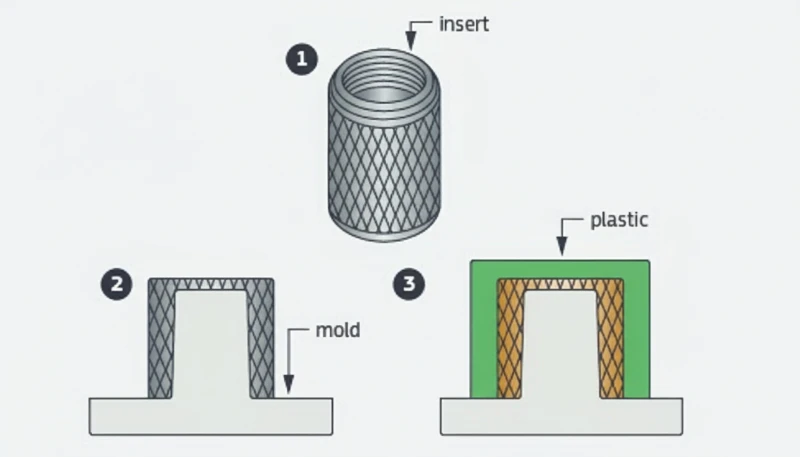
- Bij het spuitgieten van metalen inzetstukken wordt tijdens het injecteren een voorgevormd metalen onderdeel in de kunststof verankerd, zodat een permanente, dragende assemblage ontstaat.
- Mechanische verankering door kartelingen, groeven en ondersnijdingen bepaalt grotendeels de hechtsterkte; de bijdrage van lijm is secundair.
- Messing is het meest gebruikte materiaal voor inzetstukken omdat het gemakkelijk te bewerken is, corrosiebestendig is en belastingen bij draadvorming aankan.
- Verschuiving van het inzetstuk, inval en slechte hechting zijn de drie belangrijkste defecten. Elk ervan kan worden voorkomen met de juiste plaatsing van de aanspuiting, wanddikte en oppervlaktevoorbereiding.
- Dit proces presteert beter dan ultrasoon lassen en perspassing wanneer u in één cyclus een hoge torsiebestendigheid en hermetische afdichting nodig hebt.
Wat is spuitgieten met metalen inzetstukken?
Metalen insert spuitgieten wordt gedefinieerd door de functie, beperkingen en trade-offs die in deze sectie worden uitgelegd. Als je leveranciers vergelijkt of procurement plant, onze spuitgiet leveranciers sourcing guide behandelt RFQ prep, qualification en commercial risk checks.
Spuitgieten met metalen inzetstukken is een productieproces waarbij een voorgevormd metalen onderdeel in de matrijsholte wordt geplaatst voordat er gesmolten kunststof omheen wordt gespoten. Het resultaat is één permanent verbonden assemblage die de geleidbaarheid, draadsterkte en stijfheid van metaal combineert met de ontwerpvrijheid en het lage gewicht van kunststof.
Het onderscheid met overgieten1 is belangrijk. Bij overgieten wordt een tweede kunststofmateriaal over een eerste kunststofsubstraat gespoten. Inzetstukgieten2 betekent specifiek dat vóór de cyclus een vooraf vervaardigd onderdeel, vrijwel altijd van metaal maar soms van keramiek of een ander voorgevormd onderdeel, in de holte wordt geplaatst. Het metalen inzetstuk wordt doorgaans handmatig, met een robotarm of via een automatische trilvuller geladen. Zodra het inzetstuk correct is geplaatst, sluit de matrijs en stroomt gesmolten kunststof eromheen, zodat het metalen onderdeel in de uiteindelijke geometrie wordt verankerd. Dit eenstapsproces elimineert secundaire assemblagestappen zoals perspassing, ultrasoon lassen of verlijming en verlaagt zo zowel de kosten als het faalrisico.
In onze Shanghai fabriek, runnen we 47 spuitgiet machines ranging van 90T tot 1850T, wat ons de flexibility geeft om insert molding jobs te hanteren van delicate M1.0 electronic inserts tot heavy-duty automotive bushings.
"Ingegoten schroefdraad kan 5–10× meer assemblagecycli doorstaan dan zelftappende schroeven in kunststofbussen."True
Zelftappende schroeven snijden bij elke montage schroefdraad in de kunststof, waardoor het nokmateriaal geleidelijk achteruitgaat. Ingespoten messing schroefdraad verdeelt de belasting over de volledige metalen schroefdraadverbinding en behoudt de klemkracht gedurende honderden montagecycli zonder dol te draaien.
"De cyclustijden voor inzetspuitgieten zijn altijd veel langer dan standaardcycli voor spuitgieten."False
Bij geautomatiseerde plaatsing van inzetstukken bedraagt de extra tijd vaak slechts 3–5 seconden per cyclus. De injectie-, nadruk- en koelfase zijn vrijwel gelijk aan die van standaardspuitgieten. Bij grote series autoconnectoren zijn cyclustijden van 18–22 seconden, inclusief plaatsing van het inzetstuk, haalbaar.
Hoe werkt het proces voor het omsluiten van metalen inzetstukken?
Het spuitgietproces3 voor inzetstukgieten volgt dezelfde fundamentele cyclus als standaardspuitgieten, maar met één cruciale voorafgaande stap: het metalen onderdeel in de holte laden. Hieronder staat de volledige volgorde, stap voor stap.
Stap 1: voorbereiding van het inzetstuk
Voordat er kunststof stroomt, moeten de metalen inzetstukken schoon, droog en vrij van bewerkingsolie of oppervlakteverontreinigingen zijn. Veel bedrijven reinigen inzetstukken in een ultrasoonbad of dompelen ze in een oplosmiddel, gevolgd door drogen met hete lucht. Verontreinigingen op het oppervlak van het inzetstuk werken als lossingsmiddel en vernietigen de mechanische hechting tussen metaal en kunststof.
Bij sommige toepassingen moeten de inzetstukken worden voorverwarmd tot 80–120 °C. Voorverwarming verkleint het temperatuurverschil tussen de gesmolten kunststof en het koude metaal. Dit minimaliseert restspanning op het grensvlak en voorkomt voortijdige stolling, die anders een zwakke verbindingslijn zou veroorzaken. Voorverwarming is vooral belangrijk bij materialen met hoge krimp, zoals nylon en polypropyleen.
Stap 2: plaatsing van het inzetstuk
De matrijs opent en het inzetstuk wordt op de aangewezen positie aan de caviteitszijde geplaatst. Bij kleine volumes plaatsen operators inzetstukken handmatig met pincetten of vacuümstaven. Bij grote volumes plaatsen robotarmen of automatische toevoersystemen (trilkommen, vrijgavemechanismen) de inzetstukken met een positioneringsnauwkeurigheid van ±0.05 mm of beter.
Het matrijsontwerp moet positieve borgvoorzieningen bevatten, zoals veerbelaste pennen, magnetische uitsparingen of conische zittingen, die het inzetstuk tijdens het sluiten en injecteren op zijn plaats houden. Zonder borging duwt de smeltstroom onder hoge druk (doorgaans 50–150 MPa) het inzetstuk uit positie, met afgekeurde onderdelen als gevolg.
Stap 3: Matrijs sluiten, injecteren en nadrukken
Zodra het inzetstuk op zijn plaats zit, sluit de matrijs en vult de injectie-eenheid de matrijsholte met gesmolten kunststof bij temperaturen variërend van 200 °C (voor polypropyleen) tot 380 °C (voor PEEK). De smelt stroomt rond het inzetstuk en volgt elk oppervlaktekenmerk. De nadruk houdt de kunststof tegen de oppervlakken van de matrijsholte en het inzetstuk terwijl het materiaal afkoelt en krimpt.
Nadruk en nadruktijd zijn bij insert molding belangrijker dan bij standaardspuitgieten. De kunststof moet lang genoeg onder druk blijven om volumetrische krimp rond het inzetstuk te compenseren. Onvoldoende nadruk veroorzaakt inval op het buitenoppervlak tegenover het inzetstuk en holtes op het grensvlak tussen metaal en kunststof.
Stap 4: koelen en uitwerpen
Koeling beslaat 60–70% van de totale cyclustijd. De koelkanalen van de matrijs moeten warmte afvoeren uit zowel de kunststof als het metalen inzetstuk, dat als thermische massa werkt. In sommige ontwerpen werkt de warmtegeleiding van het inzetstuk in uw voordeel—messing inzetstukken helpen bijvoorbeeld de omringende kunststof sneller af te koelen.
Na het koelen opent de matrijs en wordt het afgewerkte onderdeel uitgeworpen. Uitwerppennen moeten zo worden geplaatst dat ze het inzetstuk zelf niet raken, omdat ze anders oppervlaktekenmerken kunnen beschadigen of het inzetstuk gedeeltelijk naar buiten kunnen drukken. Voor kwetsbare onderdelen heeft uitwerpen met perslucht of robotextractie de voorkeur.
Welke materialen werken het best voor spuitgieten met metalen inzetstukken?
Materiaalkeuze bij insert molding omvat twee onafhankelijke beslissingen: het materiaal van de metalen insert en het kunststofsubstraat. Het grensvlak ertussen—de hechtlijn—is afhankelijk van de wisselwerking tussen beide.
Materialen voor metalen inzetstukken
Messing (C36000 of C37700) domineert inzetstukspuitgieten om één reden: het biedt het beste algemene compromis. Het kan gemakkelijk tot complexe gekartelde en geschroefde vormen worden bewerkt, is zonder galvanische laag corrosiebestendig, geleidt warmte goed, wat tijdens het spuitgieten helpt, en kost aanzienlijk minder dan roestvast staal. Messing schroefdraadinzetstukken doorstaan herhaald montagemoment zonder vreten of vervorming van de draad.
Inzetstukken van roestvast staal (kwaliteiten 303, 304 of 316) worden gebruikt in medische hulpmiddelen, voedselcontacttoepassingen en corrosieve omgevingen waar messing zou falen. De keerzijde is hogere materiaalkosten, moeilijkere bewerking (waardoor de inzetstukprijs 2–3× stijgt) en een lagere warmtegeleiding, waardoor de koeltijd langer wordt.
Aluminium inzetstukken zijn geschikt wanneer gewichtsvermindering cruciaal is, zoals in de lucht- en ruimtevaart of draagbare elektronica. De hoge thermische geleidbaarheid van aluminium versnelt de koeling, maar de lagere hardheid beperkt de duurzaamheid van schroefdraad bij herhaalde montage. Koperen inzetstukken worden gebruikt in elektrische toepassingen waar maximale geleidbaarheid vereist is—railgeleiders, aardklemmen en connectoren voor hoge stroomsterkten.
Inzetverschuiving treedt op wanneer de smeltstroom het metalen onderdeel uit zijn beoogde positie duwt. Het resultaat is een excentrische inzet, ongelijke wanddikte en mogelijk blootgesteld metaal aan één zijde. Oorzaken zijn onder andere asymmetrische poortplaatsing, overmatige inspuitsnelheid, onvoldoende retentie van de inzet in het matrijs en onbalans in de stroming van meerdere holtes.
De kunststof moet zowel voor de toepassingseisen als voor de compatibiliteit met insert molding worden gekozen. Materialen met een hoge krimp, zoals polypropyleen (PP) en nylon (PA6, PA66), klemmen inserts tijdens het afkoelen krachtig samen—maar veroorzaken ook meer restspanning op het grensvlak. Als de wand rond de insert te dun is, kan deze spanning scheuren veroorzaken.
Technische thermoplasten zoals polycarbonaat (PC), PBT en PPS zijn populaire dragermaterialen voor insert molding, omdat ze minder krimpen (0,4–0,7% tegenover 1,5–2,5% voor PP), maatvaster zijn en hogere bedrijfstemperaturen aankunnen. PEEK wordt gebruikt in luchtvaart- en medische toepassingen waarbij het eindproduct autoclaafsterilisatie of continue temperaturen boven 250 °C moet doorstaan.
Glasgevulde kwaliteiten (PA66-GF30, PBT-GF30) worden vaak in constructieve toepassingen gebruikt, omdat de glasvezel de krimp vermindert en de stijfheid rond het inzetstuk verhoogt. Glasgevulde materialen zijn echter schurender voor de matrijs en kunnen caviteiten van gehard staal vereisen.
Hechtingsmechanisme aan het grensvlak
De verbinding tussen metaal en kunststof bij insert molding is vrijwel volledig mechanisch. Anders dan bij overspuiten, waarbij chemische compatibiliteit tussen twee kunststoffen een moleculaire binding kan vormen, vormen metaal en thermoplast geen covalente bindingen. De borging berust op drie bronnen: krimppassing door afkoeling van de kunststof, mechanische vergrendeling met oppervlaktekenmerken (kartelingen, groeven, ondersnijdingen) en wrijving door de normaalkracht van de samengedrukte kunststof.
"Een matrijsstroomsimulatie vóór het verspanen van staal kan 90% van de problemen met verschuivende inzetstukken en vloeinaden voorkomen."True
Simulatie voorspelt hoe het smeltfront met het inzetstuk zal reageren, toont drukverschillen die verschuiving veroorzaken en bepaalt lasnaadposities voordat de matrijs wordt gebouwd. De locatie van de aanspuiting of de positie van het inzetstuk in software corrigeren, kost een fractie van het aanpassen van een voltooide matrijs.
"Lijmverbinding tussen metaal en kunststof levert de voornaamste houdkracht bij insert molding."False
De verbinding bij insert molding is vrijwel volledig mechanisch. Compressie door krimppassing, vergrendeling via karteling en aangrijping in groeven vertegenwoordigen meer dan 95% van de bevestiging. Lijmhechting draagt verwaarloosbaar bij, omdat thermoplastische smelten geen covalente bindingen met metalen oppervlakken vormen.
| Materiaal | Kosten | Levensduur van de schroefdraad | Corrosiebestendigheid | Thermische geleidbaarheid |
|---|---|---|---|---|
| Messing (C36000) | Laag | Uitstekend | Goed | Hoog (120 W/m·K) |
| Roestvast staal (303/304) | Middelhoog | Goed | Uitstekend | Laag (16 W/m·K) |
| Aluminium (6061) | Gemiddeld | Eerlijk | Eerlijk | Zeer hoog (167 W/m·K) |
| Koper (C11000) | Gemiddeld | Eerlijk | Eerlijk | Hoogste (390 W/m·K) |
| Staal (1018) | Laag | Goed | Slecht (galvaniseren nodig) | Gemiddeld (50 W/m·K) |
Wat zijn de kritieke aandachtspunten bij matrijsontwerp?
De kritische vormontwerpoverwegingen zijn de hoofd categorieën of opties die in deze sectie worden uitgelegd. Het vormontwerp voor insert molding vereist meer aandacht dan een standaardvorm omdat je niet alleen de plasticstroming beheert, maar ook de precieze positionering van een rigide metalen component in een hoog druk, hoge temperatuur omgeving.
Positionering en borging van inzetstukken
De matrijsholte moet voorzieningen bevatten die het inzetstuk met een herhaalnauwkeurigheid van beter dan ±0,05 mm positioneren. Veelgebruikte oplossingen zijn conische zittingen (die het inzetstuk zelf centreren), veerbelaste borgpennen (die het inzetstuk vasthouden en tijdens het uitwerpen loslaten) en magnetische uitsparingen (voor ferromagnetische inzetstukken). De keuze hangt af van de geometrie van het inzetstuk, het productievolume en de vraag of het laden handmatig of geautomatiseerd gebeurt.
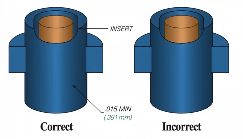
Bij matrijzen met meerdere holtes moet elke holte identieke voorzieningen voor het vasthouden van inserts hebben. Zelfs kleine verschillen in de plaatsingsdiepte van inserts tussen holtes leiden tot een inconsistente hechtsterkte en onderdeelafmetingen. Onderhoudsschema’s voor matrijzen moeten regelmatige metingen van de afmetingen van de insertzittingen omvatten.
Plaatsing van de aanspuiting en smeltstroming
De locatie van de aanspuiting bepaalt hoe het smeltfront het inzetstuk nadert en eromheen stroomt. De aanspuiting moet de stroming zo richten dat de smelt het inzetstuk symmetrisch omsluit en beide zijden ongeveer even snel vult. Asymmetrische vulling creëert een onevenwichtige druk op het inzetstuk, waardoor het tijdens de injectie verschuift.
Plaats de aanspuiting niet recht tegenover de insert. De snelle smeltstraal die het oppervlak van de insert raakt, kan twee problemen veroorzaken: de insert kan uit positie worden gedrukt en er kan aan de andere zijde een vloeilijn of laslijn ontstaan waar de gesplitste smeltstromen weer samenkomen. Een tangentiële of randaanspuiting die de stroming langs één zijde van de insert leidt, is doorgaans betrouwbaarder.
Indeling van koelkanalen
Het metalen inzetstuk werkt tijdens het koelen als koellichaam, wat afhankelijk van het ontwerp nuttig of problematisch kan zijn. Messing inzetstukken koelen de omliggende kunststof snel, maar veroorzaken ook ongelijke koeling als de koelkanalen rond het inzetstuk niet zijn uitgebalanceerd. Ongelijke koeling veroorzaakt kromtrekken en differentiële krimp.
Plaatsing van ontluchtingen
Ingesloten lucht rond kenmerken van inzetstukken (kartels, ondersnijdingen) veroorzaakt brandplekken en zwakke hechtlijnen. Ontluchtingen moeten bij de deelnaad en nabij doodlopende stromingspaden door de inzetstukgeometrie worden geslepen. De ontluchtingsdiepte moet 0.01–0.02 mm zijn — diep genoeg om lucht te laten ontsnappen en ondiep genoeg om bramen te voorkomen.
Welke ontwerprichtlijnen waarborgen betrouwbare insert-molded onderdelen?
Goede insert-molded onderdelen beginnen in de DFM-fase. De volgende richtlijnen komen voort uit productie-ervaring met duizenden ontwerpen voor insert molding.
Wanddikte rond inserts
Handhaaf tussen het buitenoppervlak van het inzetstuk en de buitenzijde van het onderdeel een minimale wanddikte van 1,5× de inzetstukdiameter. Bij een inzetstuk met een diameter van 6 mm betekent dit een buitendiameter van minstens 9 mm voor de kunststof nok. Een dunnere wand brengt risico op inval aan het buitenoppervlak en scheuren door krimpspanning mee. Een dikkere wand verspilt materiaal en verlengt de koeltijd.
De wand rond het inzetstuk moet uniform zijn. Een variabele wanddikte veroorzaakt ongelijkmatige krimp, waardoor het inzetstuk uit het midden wordt getrokken. Als het ontwerp een niet-ronde vorm van de boss vereist, gebruik dan een constante dikte tussen het inzetstuk en de buitenwand in plaats van een constant buitenprofiel.
Vorm en oppervlaktekenmerken van het inzetstuk
Karteling is de meest gebruikte oppervlaktebehandeling voor ronde inzetstukken. Diamantkarteling biedt goede axiale en roterende borging. Rechte karteling weerstaat uittrekken, maar geen rotatie. Gebruik voor maximale borging in beide richtingen een combinatie van diamantkarteling en een of meer omtrekgroeven.
Ondersnijdingen aan het inzetstuk (zoals een T-kop of flensprofiel) bieden de sterkste verankering, omdat de kunststof fysiek niet langs de ondersnijding kan worden getrokken zonder te bezwijken. Ondersnijdingen maken zowel de productie van het inzetstuk als de uitwerping uit de matrijs echter ingewikkelder; gebruik ze alleen wanneer de toepassing maximale uittreksterkte vereist.
Ontwerp tegen verdraaien en lostrekken
Bij inzetstukken met schroefdraad is borging tegen verdraaien cruciaal. Het inzetstuk mag niet in de kunststof meedraaien wanneer een schroef wordt ingedraaid of verwijderd. Twee ontwerpstrategieën werken: zeskantige of vierkante inzetstukken die in de kunststof verankeren, en gekartelde oppervlakken die een mechanische verbinding vormen. Een combinatie van beide is de betrouwbaarste aanpak voor toepassingen met een hoog koppel.
Een anti-uittrekontwerp is gericht op het maximaliseren van het afschuifoppervlak bij het grensvlak tussen inzetstuk en kunststof. Een langere aangrijplengte, bredere groeven en flenzen met een grotere diameter verhogen allemaal de uittrekkracht. Een typisch goed ontworpen messing M3-inzetstuk in PA66-GF30 moet een uittrekkracht van 500–800 N en een torsieweerstand van 0.5–1.0 N·m halen.
Tolerantieopbouw
Insert molding introduceert een extra tolerantievariabele: de positie van het inzetstuk ten opzichte van de matrijsholte. De uiteindelijke positienauwkeurigheid van het inzetstuk in het afgewerkte onderdeel hangt af van de tolerantie van de matrijszitting, de fabricagetolerantie van het inzetstuk en de krimp van de kunststof. Reken voor de positienauwkeurigheid van het inzetstuk op ±0.1–0.2 mm in een goed ontworpen en onderhouden matrijs.
Wat zijn de meest voorkomende defecten en hoe voorkomt u ze?
De meest voorkomende defecten en hoe je ze voorkomt zijn de hoofd categorieën of opties die in deze sectie worden uitgelegd. Insert molding introduceert defecten die standard injection molding nooit ziet. Hier zijn de vier meest frequent problems en hun root causes.
Verschuiving van inzetstuk (verplaatsing)
Verschuiving van het inzetstuk treedt op wanneer de smeltstroom het metalen component uit de bedoelde positie duwt. Het resultaat is een excentrisch inzetstuk, een ongelijke wanddikte en mogelijk blootliggend metaal aan één zijde. Oorzaken zijn onder meer asymmetrische plaatsing van de aanspuiting, een te hoge injectiesnelheid, onvoldoende fixatie van het inzetstuk in de matrijs en een ongebalanceerde stroming bij meerdere holten.
Uitstekende spuitgietvorm
Inval en interne holtes
Invalplekken verschijnen op het onderdeeloppervlak tegenover een dik inzetstuk, omdat de grote thermische massa langzaam afkoelt en de kunststof van de matrijsholtewand wegkrimpt. Inwendige holtes ontstaan wanneer de buitenhuid bevriest voordat de kern volledig is nagevuld.
Oplossingen: verhoog de nadruk en verleng de nadruktijd om volumetrische krimp rond het inzetstuk te compenseren. Verwarm inzetstukken voor om de temperatuurgradiënt te verkleinen. Houd een minimale wanddikte van 1.5× de diameter van het inzetstuk aan. Overweeg voor zeer dikke noksecties een schuimmiddel (microcellulair spuitgieten).
Slechte hechtsterkte
Wanneer de uittrekkracht onder de specificatie daalt, zijn oppervlakteverontreiniging op het inzetstuk, onvoldoende nadruk en voortijdig dichtvriezen de gebruikelijke oorzaken. Olie, vet of lossingsmiddel op het oppervlak van het inzetstuk voorkomt dat de kunststof zich naar het kartel- of groefprofiel vormt.
Oplossingen: voer voor alle binnenkomende inzetstukken een reinigingsprotocol in (ultrasoonbad of wassen met oplosmiddel). Verhoog de smelttemperatuur met 10–20 °C om de vloeiing in oppervlaktekenmerken te verbeteren. Verleng de nadruktijd. Beperk bij gebruik van maalgoed het aandeel maalgoed tot 15% of minder, omdat gedegradeerd materiaal slechte vloei-eigenschappen heeft.
Kromtrekken en scheuren van onderdelen
Verschilkrimp tussen de insertzone (begrensd door metaal) en de vrij krimpende kunststofwanden veroorzaakt kromtrekken. In extreme gevallen overschrijdt de restspanning rond het insert de treksterkte van de kunststof, waardoor radiale scheuren in de nokwand ontstaan.
Oplossingen: gebruik een materiaal met lagere krimp of een glasgevulde kwaliteit. Verwarm het inzetstuk voor om de temperatuurschok te verminderen. Ontwerp de nok met een uniforme wanddikte en voeg steunribben toe voor structurele ondersteuning. Het uitgloeien van het afgewerkte onderdeel bij een temperatuur onder de warmtevervormingstemperatuur van de kunststof kan restspanning verminderen zonder het onderdeel te vervormen.
Hoe test en valideert u assemblages met ingespoten inzetstukken?
Kwaliteitsvalidatie van insert-molded onderdelen gaat verder dan standaard maatinspectie. De metaal-kunststofinterface vereist specifieke mechanische tests om te verifiëren dat de verbinding aan de toepassingseisen voldoet.
Uittrektest
Een universele testmachine klemt het kunststof onderdeel vast en oefent axiale kracht uit om het inzetstuk eruit te trekken. De test meet de maximale uittrekkracht en registreert de faalwijze—of de kunststof breekt, het inzetstuk uit de karteling loskomt of de kunststof bus scheurt. Een goed ontworpen M3 messing inzetstuk in glasgevuld nylon moet consequent een uittrekkracht van 500–800 N bereiken.
Aan het begin van de productie moeten uittrekproeven worden uitgevoerd op monsters uit elke caviteit en vervolgens periodiek gedurende de productieronde. Een daling van 10–15% in de uittrekkracht ten opzichte van de eerste monsters wijst op procesverloop—doorgaans een stijgende matrijstemperatuur, materiaaldegradatie of versleten insertzittingen.
Koppeltest
Bij inzetstukken met schroefdraad wordt met een gekalibreerde momentsleutel een schroef in het inzetstuk gedraaid totdat het voorgeschreven installatiemoment is bereikt of het inzetstuk in de kunststof meedraait. Het bezwijkmoment bepaalt het maximale veilige bedrijfsmoment—voor productiespecificaties doorgaans vastgesteld op 50–60% van het bezwijkmoment.
Koppeltesten brengen problemen aan het licht die bij uittrektesten worden gemist. Een inzetstuk kan door diepe karteling een uitstekende axiale borging hebben, maar een geringe weerstand tegen rotatie als het kartelpatroon te fijn is of de kunststof de groeven niet volledig heeft gevuld.
Doorsnedeanalyse
Door een onderdeel met inzetstuk door te snijden en het snijvlak onder vergroting te onderzoeken, wordt de kwaliteit van het hechtvlak zichtbaar. Let op holtes tussen het inzetstuk en de kunststof, onvolledige vulling van kartelgroeven en invalplekken op het buitenoppervlak. Dwarsdoorsnedeanalyse is destructief en wordt doorgaans uitgevoerd tijdens de eerste proceskwalificatie en na elke gereedschapswijziging.
Milieu- en levenscyclustests
Thermische cycli (doorgaans -40 °C tot +85 °C of hoger, afhankelijk van de toepassing) testen of differentiële uitzetting tussen metaal en kunststof na verloop van tijd de hechting aantast. Thermische-schoktests met snelle temperatuurovergangen zijn bijzonder zwaar: ze leggen elke zwakke hechtlijn binnen 50–100 cycli bloot.
Blootstelling aan vocht is belangrijk voor hygroscopische materialen zoals nylon. Na 48 uur bij 85% RH en 85 °C neemt nylon voldoende vocht op om 0.5–1.0% op te zwellen, waardoor de klemmende druk op de insert met 15–25% kan afnemen. Test altijd onder realistische eindgebruiksomstandigheden.
Waar wordt metaal-insert molding in verschillende sectoren toegepast?
Inzetstukspuitgieten met metaal wordt gebruikt in elke sector die sterke, betrouwbare metaal-kunststofverbindingen nodig heeft. De vier grootste toepassingssectoren zijn de auto-industrie, elektronica, medische hulpmiddelen en consumentenproducten.
In de automobielindustrie worden meegespuitgegoten schroefdraadinzetstukken toegepast in interieurbekledingspanelen, instrumentenpaneelbehuizingen, sensorbehuizingen en elektrische connectoren onder de motorkap. Eén middelgrote auto bevat 50–100 meegespuitgegoten schroefdraadbossen. Automobielleveranciers specificeren voor elk inzetstuk uittrek- en koppelwaarden, en productieonderdelen moeten steekproeven voor statistische procesbeheersing doorstaan om de PPAP-documentatie op peil te houden.
Elektronicatoepassingen omvatten montagebussen voor printplaten, bevestigingspennen voor RF-afscherming, accuklemblokken en connectorbehuizingen.
De trend naar miniaturisering heeft geleid tot vraag naar inzetstukken tot M1.0, waarvoor precisiematrijzen met inzetstukzittingen met een tolerantie van 0,01 mm en gespecialiseerde beladingsautomatisering nodig zijn.
Fabrikanten van medische hulpmiddelen gebruiken insert molding voor instrumenthandgrepen, componenten van chirurgische instrumenten en behuizingen van diagnostische apparatuur. Roestvaststalen inzetstukken zijn standaard in deze sector omdat ze bestand zijn tegen autoclaafsterilisatie en aan biocompatibiliteitseisen voldoen. ISO 13485-kwaliteitssystemen vereisen volledige traceerbaarheid van elke partij inzetstukken tot het afgewerkte hulpmiddel.
Consumentenproducten—behuizingen van elektrisch gereedschap, keukenapparatuur, sportartikelen en speelgoed—gebruiken insert molding voor montagelocaties met schroefdraad die herhaald demonteren en monteren moeten doorstaan. De meerprijs van een messing insert (bij grote aantallen doorgaans $0.02–$0.10 per stuk) valt in het niet bij de garantiekosten van beschadigde kunststof schroefdraad.
Naast deze vier sectoren wordt insert molding toegepast in telecommunicatiehardware (ferrules voor glasvezelconnectoren, antennebeugels voor basisstations), industriële apparatuur (klephuizen, actuatorbehuizingen, sensorbevestigingen) en defensietoepassingen waarin metalen schroefdraadverbindingen met kunststof bestand moeten zijn tegen schok- en trillingsbelastingen volgens MIL-STD-normen. Opkomende EV-batterijtoepassingen gebruiken insert-molded roestvaststalen montagebossen voor constructieve bevestiging en elektrische aarding.
Ingenieurs die verbindingsmethoden beoordelen, vergelijken insert molding vaak met drie alternatieven. Elk heeft specifieke sterke punten en beperkingen.
Insert molding versus overspuiten
Bij insert molding wordt een stijf, vooraf gemaakt onderdeel (meestal metaal) in kunststof ingekapseld. Bij overmolding wordt een tweede kunststof over een eerste kunststof substraat gevormd, waardoor een zachte greep, een afdichting of een meerkleurig onderdeel ontstaat. Overmolding kan een chemische verbinding tussen de twee kunststoffen creëren als ze compatibel zijn (bijvoorbeeld TPE op PP). Insert molding is volledig afhankelijk van mechanische verankering. Kies insert molding wanneer u metaaleigenschappen nodig hebt; kies overmolding wanneer u kunststofintegratie met meerdere materialen nodig hebt.
Outsert molding is het omgekeerde van insert molding: kunststof kenmerken worden op een vlak metalen substraat gespoten in plaats van metaal in kunststof te plaatsen. Bij ultrasone insertplaatsing wordt als secundaire bewerking met hoogfrequente trillingen een metalen insert in een vooraf gevormde kunststof boss gedreven. Beide methoden vermijden de gereedschapscomplexiteit van insert molding, maar leveren in op consistentie en sterkte van de hechting.
De belangrijkste afweging: inzetspuitgieten levert sterkere, consistentere verbindingen op doordat de kunststof zich bij beheerste druk en temperatuur gelijkmatig rond het inzetstuk verdicht. Ultrasoon inbrengen creëert een verbinding die afhangt van de trillingsamplitude, inbrengdiepte en het smelten van de kunststof tijdens een korte cyclus van 0.5–2 seconden—meer variabelen en dus meer kans op inconsistentie.
Veelgestelde vragen over spuitgieten met metalen inzetstukken
Wat is de minimale wanddikte rond een metalen inzetstuk bij spuitgieten?
De usual starting point is at least 1.5 keer de insert diameter als plastic wall rond de metalen insert, met meer margin voor brittle of glass-filled resins. De wall moet ook uniform blijven rond de boss. Als één side thin is en de opposite side thick, cooling shrinkage wordt uneven en cracking risk stijgt. Voor load-bearing threads, confirm de wall met pull-out en torque tests in plaats van alleen relying op een handbook value tijdens sampling. Bevestig de keuze met production sampling data.
Kun je aluminium inzetstukken gebruiken in plaats van messing bij inzetgieten?
Ja, maar aluminium is geen directe vervanging voor brass in elke insert-molded part. Aluminum reduceert gewicht en verbetert heat transfer, maar het is softer, easier to deform tijdens loading, en geeft usually lower thread durability. Gebruik het voor lightweight housings, portable devices, of aerospace parts waar mass matters. Voor repeated screw assembly, brass of stainless steel is usually safer unless testing proves dat de aluminium insert de torque en pull-out specification onder real load en temperature meet. Bevestig de keuze met production sampling data.
Hoe nauwkeurig is de insertpositionering in insert-gegoten onderdelen?
Typische productie-insertpositionering kan ongeveer plus of min 0,05 tot 0,10 mm aanhouden wanneer de matrijs positieve insertzittingen, stabiel laden en gecontroleerd klemmen heeft. Hogere nauwkeurigheid is mogelijk, maar hangt af van de inserttolerantie, herhaalbaarheid van de lader, smeltdruk en caviteitsbalans. Beoordeel nauwkeurigheid niet alleen vanuit CAD. Valideer het met eerste-artikel CMM-controles en herhaalde controles over elke caviteit, omdat één zwakke plaatser drift kan veroorzaken die pas verschijnt nadat het gereedschap opwarmt. Bevestig de keuze met productie-steekproefgegevens.
Werkt insert molding met hoge-temperatuur kunststoffen zoals PEEK?
Ja, insert molding kan werken met high-temperature plastics zoals PEEK, PPS, PEI, en high-temperature nylon, maar de insert en vormontwerp moeten veel hogere processing temperatures kunnen hanteren. De metalen insert kan preheating nodig hebben zodat de melt niet te snel bevriest rond de knurl of groove. De leverancier heeft ook tooling steel, hot runner, en drying controls nodig die geschikt zijn voor de resin. Voor critical parts, run een material-specific trial voordat je production tooling en final dimensions commit. Bevestig de keuze met production sampling data.
Wat veroorzaakt scheuren rond de pen bij insert-gegoten onderdelen?
Scheuren rond de pen ontstaat meestal door restspanningen, ongelijke wanddikte, scherpe hoeken bij de insert, of een groot temperatuurverschil tussen de koude insert en het hete plastic. Hoogkrimpende materialen verergeren het probleem omdat het plastic wil krimpen terwijl de metalen insert beweging tegenhoudt. De gebruikelijke oplossingen zijn uniforme wanddikte, ruime afrondingen, glasgevuld of laagkrimpende kunststof, voorverwarmen van de insert, en validatie met thermische cycli in plaats van alleen inspectie bij kamertemperatuur voor verzending en goedkeuring. Bevestig de keuze met productie-steekproefgegevens.
Hoeveel inzetstukken kunnen in één enkel onderdeel worden gegoten?
Een onderdeel kan één insert of vele inserts bevatten, maar de praktische limiet wordt bepaald door loading accuracy, cycle time, cavity access, en het risico van misloaded hardware. Manual loading is meestal best voor low quantities of simple parts met één tot drie inserts. Robotic loading wordt meer attractive wanneer insert count stijgt, orientation repeatable moet zijn, of worker fatigue errors creëert. Elke added insert moet een positive seat en een clear poka-yoke feature hebben in het vormontwerp. Bevestig de keuze met production sampling data.
Is insert molding geschikt voor productie met een laag volume?
Insert molding kan geschikt zijn voor low-volume productie wanneer het onderdeel betrouwbare sterkte, gesloten metaal-plastic integratie, of repeatable positionering nodig heeft die secondary insertion niet kan leveren. Het kan niet economisch zijn voor simple threaded bosses onder een paar honderd onderdelen, omdat de vorm insert seats en extra sampling werk vereist. Voor prototypes of bridge runs, vergelijk drie routes: manual insert molding, ultrasonic insertion na molding, en machining plus assembly. Kies op basis van totale risico, niet alleen tooling kosten voor de buyer. Bevestig de keuze met production sampling data.
overmolding: Overmolding is een tweetraps spuitgietproces waarbij een tweede kunststof over een eerste substraat wordt gevormd om een onderdeel van meerdere materialen of kleuren te maken. ↩
insert molding: Insert molding is een productieproces waarbij een voorgevormde component in de holte van een spuitgietmatrijs wordt geplaatst en met gesmolten kunststof wordt omhuld tot één geïntegreerde assemblage. ↩
spuitgietproces: Het spuitgietproces is een cyclische productiemethode waarbij kunststofkorrels worden gesmolten, onder druk in een matrijsholte worden geïnjecteerd, afgekoeld en als vast onderdeel uitgeworpen. ↩