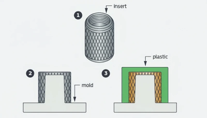
- Lo stampaggio con inserti metallici incorpora un componente metallico preformato nella plastica durante l'iniezione, creando un assieme permanente e portante.
- La ritenzione meccanica dovuta a zigrinature, scanalature e sottosquadri domina la resistenza del legame; il contributo dell'adesivo è secondario.
- L’ottone è il materiale più comune per gli inserti perché è facile da lavorare, resiste alla corrosione e sopporta i carichi di formatura della filettatura.
- Lo spostamento dell'inserto, i risucchi e la scarsa adesione sono i tre difetti principali; ciascuno può essere prevenuto mediante il posizionamento del punto di iniezione, lo spessore delle pareti e la preparazione della superficie.
- Questo processo supera la saldatura a ultrasuoni e il montaggio a pressione quando servono elevata resistenza alla coppia e tenuta ermetica in un unico ciclo.
Che cos’è lo stampaggio a iniezione con inserti metallici?
La stampa ad iniezione con inserti metallici è definita dalla funzione, dai vincoli e dai compromessi spiegati in questa sezione. Se stai confrontando fornitori o pianificando l’acquisto, la nostra guida per la selezione dei fornitori di stampaggio ad iniezione copre la preparazione della RFQ, la qualificazione e i controlli del rischio commerciale.
Lo stampaggio a iniezione con inserti metallici è un processo produttivo in cui un componente metallico preformato viene posizionato nella cavità dello stampo prima di iniettare la plastica fusa attorno ad esso. Il risultato è un unico assieme permanentemente unito che combina conducibilità, resistenza della filettatura e rigidità del metallo con libertà progettuale e leggerezza della plastica.
La distinzione dal sovrastampaggio1 è importante. Il sovrastampaggio applica un secondo materiale plastico su un primo substrato plastico. Lo stampaggio con inserti2 prevede invece il posizionamento nella cavità, prima dell’inizio del ciclo, di un componente prefabbricato, quasi sempre metallico ma talvolta ceramico o prestampato. L’inserto metallico viene normalmente caricato a mano, con un braccio robotico o tramite un alimentatore vibrante automatico. Una volta posizionato correttamente, lo stampo si chiude e la plastica fusa fluisce attorno all’inserto, bloccando il componente metallico nella geometria finale. Questo processo in un solo ciclo elimina operazioni secondarie quali montaggio a pressione, saldatura a ultrasuoni o incollaggio, riducendo costi e rischio di guasto.
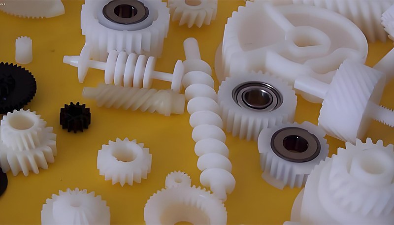
Nel nostro stabilimento di Shanghai, abbiamo 47 macchine per stampaggio ad iniezione da 90T a 1850T, che ci danno la flessibilità di gestire lavori di stampaggio con inserti da delicati inserti elettronici M1.0 a boccole automotive resistenti.
"Le filettature costampate con inserto possono resistere a un numero di cicli di assemblaggio 5–10× superiore rispetto alle viti autofilettanti nelle colonnine in plastica."True
Le viti autofilettanti creano la filettatura nella plastica a ogni inserimento, degradando progressivamente il materiale della colonnina. Le filettature in ottone sovrastampate distribuiscono il carico sull'intero ingaggio della filettatura metallica, mantenendo la forza di serraggio per centinaia di cicli di assemblaggio senza spanatura.
"I tempi di ciclo dello stampaggio con inserti sono sempre molto più lunghi rispetto ai cicli standard di stampaggio a iniezione."False
Con il caricamento automatico degli inserti, il tempo aggiuntivo è spesso di soli 3–5 secondi per ciclo. Le fasi di iniezione, compattazione e raffreddamento sono quasi identiche allo stampaggio standard. Nei lavori ad alto volume per connettori automobilistici sono ottenibili tempi di ciclo di 18–22 secondi, incluso il posizionamento dell'inserto.
Come funziona il processo di stampaggio con inserti metallici?
Il processo di stampaggio a iniezione3 con inserti segue lo stesso ciclo fondamentale dello stampaggio standard, ma con una fase preliminare essenziale: il caricamento del componente metallico nella cavità. Ecco la sequenza completa, descritta passo per passo.
Fase 1: preparazione dell’inserto
Prima che scorra la plastica, gli inserti metallici devono essere puliti, asciutti e privi di oli di lavorazione o contaminanti superficiali. Molte officine sottopongono gli inserti a un bagno di pulizia a ultrasuoni o a un’immersione in solvente, seguita da asciugatura ad aria calda. I contaminanti sulla superficie dell’inserto agiscono come agenti distaccanti, distruggendo il legame meccanico tra metallo e plastica.
Alcune applicazioni richiedono il preriscaldamento degli inserti a 80–120 °C. Il preriscaldamento riduce la differenza di temperatura tra la plastica fusa e il metallo freddo, minimizzando la tensione residua all’interfaccia e impedendo il congelamento prematuro che altrimenti creerebbe una linea di giunzione debole. Il preriscaldamento è particolarmente importante con materiali ad alto ritiro come nylon e polipropilene.
Fase 2: posizionamento dell’inserto
Lo stampo si apre e l’inserto viene collocato nella posizione prevista sul lato cavità. Per la produzione a basso volume, gli operatori caricano gli inserti manualmente con pinzette o manipolatori a vuoto. Per le produzioni ad alto volume, bracci robotici o sistemi di alimentazione automatici, come alimentatori a tazza vibrante e meccanismi di separazione, posizionano gli inserti con una precisione di ±0,05 mm o superiore.
La progettazione dello stampo deve includere elementi di ritenuta positiva, come perni a molla, sedi magnetiche o appoggi conici, che mantengano l’inserto in posizione durante la chiusura e l’iniezione. Senza ritenuta, il flusso del fuso ad alta pressione, normalmente 50-150 MPa, spinge l’inserto fuori posizione, producendo pezzi di scarto.
Fase 3: chiusura dello stampo, iniezione e compattazione
Una volta posizionato l’inserto, lo stampo si chiude e l’unità di iniezione riempie la cavità con plastica fusa a temperature comprese tra 200 °C (per il polipropilene) e 380 °C (per il PEEK). Il fuso scorre attorno all’inserto, adattandosi a ogni caratteristica superficiale. La pressione di mantenimento tiene la plastica contro le superfici della cavità e dell’inserto mentre il materiale si raffredda e si ritira.
La pressione e il tempo di mantenimento sono più critici nello stampaggio con inserti rispetto allo stampaggio standard. La plastica deve rimanere sotto pressione abbastanza a lungo da compensare il ritiro volumetrico attorno all’inserto. Un mantenimento insufficiente provoca risucchi sulla superficie esterna opposta all’inserto e vuoti nell’interfaccia metallo-plastica.
Fase 4: raffreddamento ed espulsione
Il raffreddamento rappresenta il 60–70% del tempo ciclo totale. I canali di raffreddamento dello stampo devono sottrarre calore sia alla plastica sia all’inserto metallico, che agisce da massa termica. In alcuni progetti, la conducibilità termica dell’inserto è vantaggiosa: gli inserti in ottone, per esempio, accelerano il raffreddamento della plastica circostante.
Dopo il raffreddamento, lo stampo si apre e il pezzo finito viene espulso. I perni di espulsione devono essere posizionati in modo da evitare il contatto con l’inserto stesso, che potrebbe danneggiare le geometrie superficiali o spingere parzialmente l’inserto verso l’esterno. Per i pezzi delicati si preferisce l’espulsione mediante getto d’aria o l’estrazione robotizzata.
Quali materiali sono più adatti allo stampaggio con inserti metallici?
La selezione dei materiali nello stampaggio a inserti comporta due decisioni indipendenti: il materiale dell’inserto metallico e il substrato plastico. L’interfaccia tra i due, ossia la linea di adesione, dipende dalla loro interazione.
Materiali degli inserti metallici
L’ottone (C36000 o C37700) domina lo stampaggio con inserti per un motivo: rappresenta il miglior compromesso complessivo. Si lavora facilmente in forme zigrinate e filettate complesse, resiste alla corrosione senza placcatura, conduce bene il calore (favorendo lo stampaggio) e costa molto meno dell’acciaio inossidabile. Negli inserti filettati, l’ottone sopporta coppie di serraggio ripetute senza grippaggio né deformazione della filettatura.
Gli inserti in acciaio inossidabile (gradi 303, 304 o 316) sono utilizzati nei dispositivi medicali, nelle applicazioni a contatto con gli alimenti e negli ambienti corrosivi nei quali l’ottone non sarebbe adatto. Il compromesso consiste in un costo maggiore del materiale, una lavorazione più difficile (che aumenta di 2–3 volte il prezzo dell’inserto) e una minore conducibilità termica, che prolunga il tempo di raffreddamento.
Gli inserti in alluminio sono adatti quando la riduzione del peso è essenziale, ad esempio nei settori aerospaziale o dell’elettronica portatile. L’elevata conducibilità termica dell’alluminio accelera il raffreddamento, ma la minore durezza limita la durata delle filettature in caso di assemblaggi ripetuti. Gli inserti in rame sono impiegati nelle applicazioni elettriche che richiedono la massima conducibilità—barre collettrici, terminali di messa a terra e connettori ad alta corrente.
Selezione del substrato plastico
Soluzioni: Utilizzare la simulazione del flusso di stampaggio per verificare il riempimento bilanciato attorno a ogni inserto. Ridurre la velocità di iniezione nella prima fase per diminuire la pressione dinamica sull’inserto. Migliorare i sistemi di ritenzione dello stampo: passare da sedi gravitazionali a perni a molla o accoppiamenti forzati conici. Negli stampi a più cavità, bilanciare il sistema di canali di colata in modo che tutte le cavità si riempiano alla stessa velocità.
I tecnopolimeri termoplastici come policarbonato (PC), PBT e PPS sono substrati diffusi per lo stampaggio con inserti perché offrono un ritiro inferiore (0.4–0.7% rispetto a 1.5–2.5% per il PP), migliore stabilità dimensionale e temperature operative più elevate. Il PEEK è utilizzato in applicazioni aerospaziali e medicali in cui il pezzo finito deve resistere alla sterilizzazione in autoclave o a temperature continue superiori a 250 °C.
I gradi rinforzati con vetro, come PA66-GF30 e PBT-GF30, sono comuni nelle applicazioni strutturali perché la fibra riduce il ritiro e aumenta la rigidità attorno all’inserto. Tuttavia, questi materiali sono più abrasivi per lo stampo e possono richiedere cavità in acciaio temprato.
Meccanismo di adesione all’interfaccia
Il legame tra metallo e plastica nello stampaggio con inserti e quasi interamente meccanico. A differenza del sovrastampaggio, in cui la compatibilita chimica tra due plastiche puo creare un legame molecolare, metallo e termoplastico non formano legami covalenti. La ritenzione deriva da tre fonti: la compressione per calettamento dovuta al raffreddamento della plastica, l’incastro meccanico con le caratteristiche superficiali (zigrinature, scanalature, sottosquadri) e l’attrito generato dalla forza normale esercitata dalla plastica compressa.
"La simulazione del flusso nello stampo prima di lavorare l’acciaio può prevenire il 90% dei problemi di spostamento degli inserti e delle linee di saldatura."True
La simulazione prevede come il fronte del fuso interagirà con l’inserto, mostrando le differenze di pressione che causano lo spostamento e individuando le posizioni delle linee di saldatura prima della costruzione dello stampo. Correggere nel software la posizione del punto di iniezione o dell’inserto costa una frazione rispetto alla modifica di uno stampo finito.
"L'incollaggio adesivo tra metallo e plastica fornisce la principale forza di ritenzione nello stampaggio a inserti."False
Il legame nello stampaggio con inserti è in larghissima parte meccanico. La compressione per accoppiamento da ritiro, l'incastro della zigrinatura e l'aggancio nelle scanalature rappresentano oltre il 95% della ritenzione. Il legame adesivo contribuisce in misura trascurabile, perché i fusi termoplastici non formano legami covalenti con le superfici metalliche.
| Materiale | Costo | Durata della filettatura | Resistenza alla corrosione | Conduttività termica |
|---|---|---|---|---|
| Ottone (C36000) | Basso | Eccellente | Buono | Alta (120 W/m·K) |
| Acciaio inossidabile (303/304) | Medio-alto | Buono | Eccellente | Bassa (16 W/m·K) |
| Alluminio (6061) | Medio | Fiera | Fiera | Molto alta (167 W/m·K) |
| Rame (C11000) | Medio | Fiera | Fiera | Massima (390 W/m·K) |
| Acciaio (1018) | Basso | Buono | Scarso (richiede galvanizzazione) | Media (50 W/m·K) |
Quali sono gli aspetti critici della progettazione dello stampo?
Le considerazioni critiche sulla progettazione dello stampo sono le principali categorie o opzioni spiegate in questa sezione. La progettazione dello stampo per lo stampaggio con inserti richiede più attenzione rispetto a un stampo standard perché si gestisce non solo il flusso della plastica, ma anche il posizionamento preciso di un componente metallico rigido in un ambiente ad alta pressione e alta temperatura.
Posizionamento e ritenuta degli inserti
La cavità deve includere caratteristiche che posizionino l’inserto con una ripetibilità migliore di ±0,05 mm. Le soluzioni comuni comprendono sedi coniche (che autocentrano l’inserto), perni di ritenuta a molla (che afferrano l’inserto e lo rilasciano durante l’espulsione) e tasche magnetiche (per inserti ferromagnetici). La scelta dipende dalla geometria dell’inserto, dal volume di produzione e dal tipo di caricamento, manuale o automatizzato.
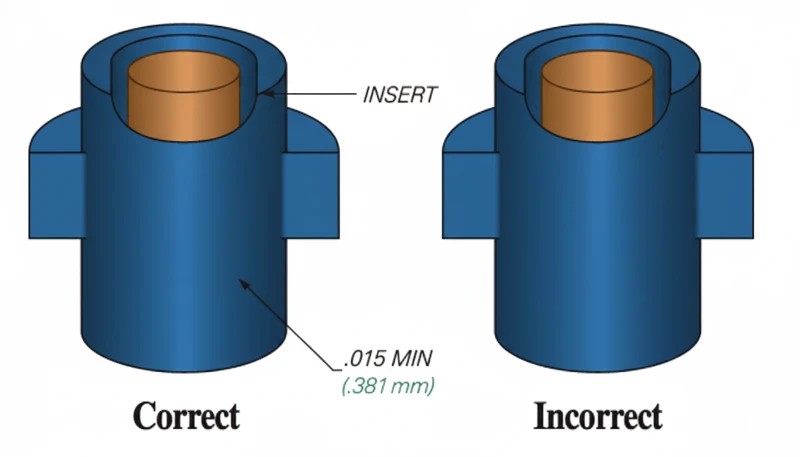
Negli stampi multicavità, ogni cavità deve presentare caratteristiche di ritenzione dell’inserto identiche. Anche piccole differenze nella profondità di alloggiamento degli inserti tra le cavità producono resistenza di adesione e dimensioni dei pezzi non uniformi. I programmi di manutenzione degli stampi devono includere la misurazione periodica delle dimensioni delle sedi degli inserti.
Posizionamento del punto di iniezione e flusso del fuso
La posizione del punto di iniezione determina il modo in cui il fronte di fusione si avvicina all’inserto e scorre attorno a esso. Il punto di iniezione deve dirigere il flusso in modo che il fuso avvolga simmetricamente l’inserto, riempiendo entrambi i lati approssimativamente alla stessa velocità. Un riempimento asimmetrico crea una pressione sbilanciata sull’inserto, causandone lo spostamento durante l’iniezione.
Evitare di posizionare il punto di iniezione direttamente di fronte all’inserto. Il getto di materiale fuso ad alta velocità che colpisce la superficie dell’inserto può causare due problemi: può spostare l’inserto dalla sua posizione e può creare una linea di flusso o di saldatura sul lato opposto, dove i flussi separati di materiale fuso si ricongiungono. Un punto di iniezione tangenziale o laterale che diriga il flusso lungo un lato dell’inserto è generalmente più affidabile.
Configurazione dei canali di raffreddamento
Durante il raffreddamento, l’inserto metallico funge da dissipatore di calore, cosa che può essere utile o problematica a seconda del progetto. Gli inserti in ottone raffreddano rapidamente la plastica circostante, ma creano anche un raffreddamento non uniforme se i canali non sono bilanciati attorno all’inserto. Un raffreddamento irregolare causa deformazione e ritiro differenziale.
Posizionamento degli sfiati
L’aria intrappolata attorno agli elementi dell’inserto (zigrinature, sottosquadri) crea bruciature e linee di giunzione deboli. Gli sfiati devono essere rettificati sulla linea di divisione e in prossimità di qualsiasi percorso di flusso cieco creato dalla geometria dell’inserto. La profondità dello sfiato deve essere di 0,01–0,02 mm: sufficiente a far uscire l’aria, ma abbastanza ridotta da evitare la formazione di bava.
Quali linee guida di progettazione garantiscono pezzi affidabili stampati con inserti?
I buoni componenti stampati con inserti nascono nella fase DFM. Le linee guida seguenti derivano dall’esperienza produttiva maturata su migliaia di progetti di componenti stampati con inserti.
Spessore della parete attorno agli inserti
Mantenere uno spessore minimo della parete pari a 1.5× il diametro dell’inserto tra la superficie esterna dell’inserto e l’esterno del pezzo. Per un inserto da 6 mm di diametro, ciò significa almeno 9 mm di diametro esterno sulla colonnina in plastica. Uno spessore minore rischia di causare risucchi sulla superficie esterna e cricche da tensione di ritiro. Uno spessore maggiore spreca materiale e prolunga il raffreddamento.
La parete deve essere uniforme attorno all’inserto. Uno spessore variabile crea un ritiro non uniforme, che sposta l’inserto dal centro. Se il progetto richiede una forma non circolare della borchia, mantenere costante lo spessore tra l’inserto e la parete esterna anziché il profilo esterno.
Forma e caratteristiche superficiali dell’inserto
La zigrinatura è il trattamento superficiale più comune per gli inserti tondi. La zigrinatura a diamante offre una buona ritenzione assiale e rotazionale. Quella diritta resiste all’estrazione ma non alla rotazione. Per la massima ritenzione in entrambe le direzioni, utilizzare una combinazione di zigrinatura a diamante e una o più scanalature circonferenziali.
I sottosquadri sull’inserto (come una testa a T o un profilo flangiato) garantiscono la ritenzione più elevata perché la plastica non può fisicamente superare il sottosquadro senza cedere. Tuttavia, i sottosquadri complicano sia la produzione dell’inserto sia l’espulsione dallo stampo: utilizzarli solo quando l’applicazione richiede la massima resistenza all’estrazione.
Progettazione antirotazione e antisfilamento
Per gli inserti filettati, impedire la rotazione è essenziale. L’inserto non deve ruotare nella plastica quando una vite viene avvitata o rimossa. Sono efficaci due strategie progettuali: corpi dell’inserto esagonali o quadrati che si bloccano nella plastica e superfici zigrinate che creano un incastro meccanico. La combinazione di entrambe è l’approccio più affidabile per applicazioni a coppia elevata.
La progettazione anti-sfilamento punta a massimizzare l’area di taglio all’interfaccia tra inserto e plastica. Una maggiore lunghezza di presa, scanalature più larghe e flange di diametro superiore aumentano tutte la forza di estrazione. Un inserto M3 in ottone ben progettato in PA66-GF30 deve raggiungere normalmente una forza di estrazione di 500–800 N e una resistenza alla coppia di 0,5–1,0 N·m.
Accumulo delle tolleranze
Lo stampaggio con inserti introduce un’ulteriore variabile di tolleranza: la posizione dell’inserto rispetto alla cavità dello stampo. La precisione posizionale finale dell’inserto nel pezzo finito dipende dalla tolleranza della sede nello stampo, dalla tolleranza di fabbricazione dell’inserto e dal ritiro della plastica. Per uno stampo ben progettato e sottoposto a corretta manutenzione, prevedi ±0.1–0.2 mm per la precisione posizionale dell’inserto.
Quali sono i difetti più comuni e come si prevengono?
I difetti più comuni e come prevenirli sono le principali categorie o opzioni spiegate in questa sezione. Lo stampaggio con inserti introduce difetti che la stampa ad iniezione standard non vede mai. Ecco i quattro problemi più frequenti e le loro cause principali.
Spostamento dell’inserto
Lo spostamento dell’inserto si verifica quando il flusso del fuso spinge il componente metallico fuori dalla posizione prevista. Il risultato è un inserto decentrato, spessore delle pareti non uniforme e possibile esposizione del metallo su un lato. Le cause principali comprendono il posizionamento asimmetrico del punto di iniezione, una velocità di iniezione eccessiva, una ritenzione insufficiente dell’inserto nello stampo e un flusso multicavità non bilanciato.
Soluzioni: utilizzare la simulazione del flusso nello stampo per verificare il riempimento bilanciato attorno a ogni inserto. Ridurre la velocità di iniezione nella prima fase per diminuire la pressione dinamica sull’inserto. Migliorare gli elementi di ritenuta nello stampo, passando da sedi per gravità a perni caricati a molla o accoppiamenti conici a interferenza. Negli stampi multicavità, bilanciare il sistema di canali affinché tutte le cavità si riempiano alla stessa velocità.
Stampaggio a inserto
I risucchi compaiono sulla superficie del pezzo opposta a un inserto spesso perché la grande massa termica si raffredda lentamente e la plastica si ritira allontanandosi dalla parete della cavità. I vuoti si formano internamente quando lo strato esterno solidifica prima che il nucleo sia stato completamente compattato.
Soluzioni: aumentare la pressione di mantenimento e prolungarne la durata per compensare il ritiro volumetrico attorno all’inserto. Preriscaldare gli inserti per ridurre il gradiente di temperatura. Mantenere uno spessore minimo della parete pari a 1,5 volte il diametro dell’inserto. Per sezioni di colonnine molto spesse, valutare l’uso di un agente espandente (stampaggio microcellulare).
Scarsa forza di adesione
Quando la forza di estrazione scende sotto specifica, le cause più comuni sono la contaminazione superficiale dell’inserto, una pressione di mantenimento insufficiente e una solidificazione prematura. Olio, grasso o distaccante sulla superficie dell’inserto impediscono alla plastica di conformarsi al profilo della zigrinatura o della scanalatura.
Soluzioni: implementare un protocollo di pulizia (bagno a ultrasuoni o lavaggio con solvente) per tutti gli inserti in ingresso. Aumentare la temperatura del fuso di 10–20 °C per migliorare il flusso nelle caratteristiche superficiali. Prolungare il tempo di mantenimento. Se si utilizza materiale rimacinato, limitarne la percentuale al 15% o meno, poiché il materiale degradato presenta scarse caratteristiche di scorrimento.
Deformazione e fessurazione del pezzo
Il ritiro differenziale tra l’area dell’inserto, vincolata dal metallo, e le pareti di plastica libere di ritirarsi causa deformazioni. Nei casi estremi, la tensione residua intorno all’inserto supera la resistenza alla trazione della plastica, provocando cricche radiali nella parete della borchia.
Soluzioni: utilizzare un materiale a minore ritiro o un grado caricato vetro. Preriscaldare l’inserto per ridurre lo shock termico. Progettare la colonnina con spessore uniforme delle pareti e aggiungere nervature di rinforzo per il supporto strutturale. La ricottura del pezzo finito a una temperatura inferiore alla temperatura di deflessione termica della plastica può alleviare le tensioni residue senza deformarlo.
Come collaudare e convalidare i gruppi con inserti sovrastampati?
La convalida qualitativa dei pezzi stampati con inserti va oltre il normale controllo dimensionale. L’interfaccia metallo-plastica richiede prove meccaniche dedicate per verificare che il legame soddisfi i requisiti dell’applicazione.
Prova di estrazione
Una macchina universale di prova afferra il pezzo in plastica e applica una forza assiale per estrarre l’inserto. La prova misura la forza massima di estrazione e registra la modalità di cedimento: frattura della plastica, distacco dell’inserto dalla zigrinatura o rottura del bossolo in plastica. Un inserto M3 in ottone ben progettato nel nylon rinforzato con fibra di vetro dovrebbe raggiungere con costanza una forza di estrazione di 500–800 N.
La prova di estrazione deve essere eseguita su campioni di ogni cavità all’inizio della produzione e poi periodicamente durante il lotto. Una riduzione del 10–15% della forza rispetto ai campioni iniziali segnala una deriva del processo, normalmente dovuta all’aumento della temperatura dello stampo, al degrado del materiale o all’usura delle sedi degli inserti.
Prova di coppia
Per gli inserti filettati, una chiave dinamometrica calibrata avvita una vite nell’inserto finché non viene raggiunta la coppia di installazione specificata oppure l’inserto ruota nella plastica. Il valore della coppia a rottura definisce la massima coppia di esercizio sicura, generalmente impostata al 50–60% della coppia di rottura nelle specifiche di produzione.
La prova di coppia rileva problemi che la prova di estrazione non individua. Un inserto può avere un’eccellente tenuta assiale grazie a una zigrinatura profonda, ma una scarsa resistenza alla rotazione se il disegno della zigrinatura è troppo fine o se la plastica non ha riempito completamente le scanalature.
Analisi della sezione trasversale
Sezionando un componente stampato con inserto ed esaminando la superficie di taglio a ingrandimento si rivela la qualità dell’interfaccia di adesione. Cercare vuoti tra inserto e plastica, riempimento incompleto delle scanalature zigrinate e risucchi sulla superficie esterna. L’analisi della sezione è distruttiva e viene generalmente eseguita durante la qualificazione iniziale del processo e dopo qualsiasi modifica dello stampo.
Prove ambientali e del ciclo di vita
I cicli termici (in genere da -40 °C a +85 °C o più, secondo l’applicazione) verificano se l’espansione differenziale tra metallo e plastica degrada il legame nel tempo. La prova di shock termico con rapide transizioni di temperatura è particolarmente severa: evidenzia qualsiasi linea di giunzione debole entro 50–100 cicli.
L’esposizione all’umidità è importante per i materiali igroscopici come il nylon. Dopo 48 ore all’85% RH e a 85 °C, il nylon assorbe umidità sufficiente a rigonfiarsi dello 0.5–1.0%, riducendo del 15–25% la presa a compressione sull’inserto. Eseguire sempre le prove in condizioni d’uso finali realistiche.
In quali settori viene utilizzato lo stampaggio con inserti metallici?
Lo stampaggio con inserti metallici serve qualsiasi settore che richieda legami forti e affidabili tra metallo e plastica. I quattro principali settori applicativi sono automotive, elettronica, dispositivi medicali e prodotti di consumo.
Nel settore automobilistico, gli inserti filettati sovrastampati sono presenti nei pannelli dei rivestimenti interni, negli alloggiamenti dei quadri strumenti, nei corpi dei sensori e nei connettori elettrici del vano motore. Una singola automobile di medie dimensioni contiene 50–100 bossoli filettati sovrastampati. I fornitori automobilistici specificano valori di estrazione e coppia per ogni inserto e i componenti di produzione devono superare il campionamento del controllo statistico di processo per mantenere la documentazione PPAP.
Le applicazioni elettroniche includono colonnine di montaggio per PCB, perni di fissaggio per schermature RF, morsettiere per batterie e alloggiamenti per connettori.
La tendenza alla miniaturizzazione ha favorito la domanda di inserti piccoli fino a M1.0, che richiedono stampi di precisione con sedi degli inserti aventi tolleranza di 0,01 mm e automazione specializzata per il caricamento.
I produttori di dispositivi medici usano lo stampaggio con inserti per impugnature, strumenti chirurgici e alloggiamenti diagnostici. Gli inserti inox sono standard perché resistono alla sterilizzazione in autoclave e soddisfano la biocompatibilità. I sistemi ISO 13485 richiedono la piena tracciabilità di ogni lotto di inserti fino al dispositivo finito.
I prodotti di consumo — involucri di elettroutensili, elettrodomestici da cucina, attrezzature sportive e giocattoli — usano lo stampaggio con inserti per i punti di assemblaggio filettati che devono resistere a ripetuti montaggi e smontaggi. Il sovrapprezzo di un inserto in ottone, in genere 0,02–0,10 dollari ciascuno sui grandi volumi, è trascurabile rispetto al costo in garanzia di una filettatura plastica spanata.
Oltre a questi quattro settori, lo stampaggio con inserti viene utilizzato nelle apparecchiature per telecomunicazioni, come ferrule per connettori in fibra ottica e staffe per antenne di stazioni base, nelle attrezzature industriali, come corpi valvola, alloggiamenti di attuatori e supporti per sensori, e nelle applicazioni per la difesa in cui le giunzioni filettate metallo-plastica devono resistere ai carichi d’urto e vibrazione previsti dalle norme MIL-STD. Le nuove applicazioni per batterie EV impiegano colonnine di montaggio in acciaio inossidabile stampate con inserto per il fissaggio strutturale e la messa a terra elettrica.
Gli ingegneri che valutano i metodi di giunzione spesso confrontano lo stampaggio con inserti con tre alternative. Ognuna presenta vantaggi e limiti specifici.
Stampaggio con inserti e sovrastampaggio
Lo stampaggio a inserti incapsula nella plastica un componente rigido prefabbricato, solitamente metallico. Il sovrastampaggio applica un secondo materiale plastico su un primo substrato plastico, creando un’impugnatura morbida, una guarnizione o un pezzo multicolore. Se le due plastiche sono compatibili, il sovrastampaggio può creare un legame chimico tra loro, ad esempio TPE su PP. Lo stampaggio a inserti si basa interamente sulla ritenzione meccanica. Scegli lo stampaggio a inserti quando servono le proprietà del metallo; scegli il sovrastampaggio quando serve l’integrazione di più materiali plastici.
L’outsert molding è l’opposto dell’insert molding: inietta elementi in plastica su un substrato metallico piano, anziché collocare il metallo all’interno della plastica. L’inserimento a ultrasuoni spinge un inserto metallico in un bossolo di plastica preformato utilizzando vibrazioni ad alta frequenza come operazione secondaria. Entrambi evitano la complessità dello stampo per insert molding, ma sacrificano uniformità e resistenza del legame.
Il compromesso principale: il sovrastampaggio di inserti produce legami più resistenti e uniformi perché la plastica si compatta in modo omogeneo attorno all’inserto a pressione e temperatura controllate. L’inserimento a ultrasuoni crea un legame che dipende dall’ampiezza delle vibrazioni, dalla profondità d’inserimento e dalla fusione della plastica durante un breve ciclo di 0.5–2 secondi—più variabili e maggiori possibilità di disuniformità.
Domande frequenti sullo stampaggio a iniezione con inserti metallici
Qual è lo spessore minimo della parete attorno a un inserto metallico nello stampaggio a iniezione?
Il punto di partenza usuale è almeno 1,5 volte il diametro dell’inserto come parete plastica intorno all’inserto metallico, con maggiore margine per resine fragili o con carica di vetro. La parete deve anche rimanere uniforme intorno al boss. Se un lato è sottile e il lato opposto è spesso, il ritiro durante il raffreddamento diventa irregolare e il rischio di cracking aumenta. Per i fili portanti, confermare la parete con test di estrazione e torsione invece di affidarsi solo a un valore di manuale durante il campionamento. Confermare la scelta con dati di campionamento di produzione.
Puoi usare inserti in alluminio invece che in ottone nello stampaggio per inserimento?
Sì, ma l’alluminio non è un sostituto diretto dell’ottone in ogni componente stampato con inserti. L’alluminio riduce il peso e migliora il trasferimento di calore, ma è più morbido, più facile da deformare durante il caricamento e di solito offre una minore durabilità della filettatura. Usalo per custodie leggere, dispositivi portatili o componenti aerospaziali dove la massa è importante. Per assemblaggio ripetuto con viti, l’ottone o l’acciaio inossidabile sono di solito più sicuri, a meno che i test non dimostrino che l’inserto in alluminio soddisfi le specifiche di coppia e strappo sotto carico e temperatura reali. Conferma la scelta con i dati di campionatura di produzione.
Quanto è precisa il posizionamento degli inserti nelle parti stampate a iniezione con inserti?
Il posizionamento tipico degli inserti in produzione può mantenere circa più o meno 0,05-0,10 mm quando lo stampo ha sedi positive per gli inserti, caricamento stabile e serraggio controllato. Una precisione più stretta è possibile, ma dipende dalla tolleranza dell’inserto, dalla ripetibilità del caricatore, dalla pressione di fusione e dall’equilibrio della cavità. Non giudicare la precisione solo dal CAD. Validala con controlli CMM sul primo articolo e ripeti i controlli su ogni cavità, perché un localizzatore debole può causare deriva che appare solo dopo il riscaldamento dello stampo. Conferma la scelta con i dati di campionatura di produzione.
La stampa ad inserto funziona con plastiche ad alta temperatura come il PEEK?
Sì, lo stampaggio con inserti può funzionare con plastiche ad alta temperatura come PEEK, PPS, PEI e nylon ad alta temperatura, ma la progettazione dell’inserto e dello stampo deve gestire temperature di processo molto più elevate. L’inserto metallico potrebbe necessitare pre-riscaldamento così che il materiale fuso non si solidifichi troppo rapidamente intorno alla zigrinatura o alla scanalatura. Il fornitore necessita anche di acciaio per utensili, runner caldo e controlli di essiccazione adatti alla resina. Per parti critiche, eseguire una prova specifica per il materiale prima di impegnarsi nella produzione dello stampo e delle dimensioni finali. Confermare la scelta con dati di campionamento di produzione.
Cosa causa la rottura dei pezzi stampati per inserzione attorno al perno?
Il cracking intorno al boss deriva generalmente da stress residuo, parete non uniforme, angoli netti vicino all’inserto, o una grande differenza di temperatura tra l’inserto freddo e la plastica fusa calda. Materiali con alto ritiro aggravano il problema perché la plastica tende a contrarsi mentre l’inserto metallico limita il movimento. Le soluzioni normali sono parete uniforme, ampi raccordi, resina con carica di vetro o con ritiro ridotto, pre-riscaldamento dell’inserto e validazione con cicli termici invece di solo controllo a temperatura ambiente prima della spedizione e approvazione. Confermare la scelta con dati di campionamento di produzione.
Quanti inserti possono essere stampati in una singola parte?
Un pezzo può contenere un inserto o molti inserti, ma il limite pratico è determinato dalla precisione di caricamento, tempo di ciclo, accesso alla cavità e rischio di hardware caricato erroneamente. Il caricamento manuale è generalmente meglio per quantità ridotte o parti semplici con uno a tre inserti. Il caricamento robotico diventa più interessante quando il numero di inserti aumenta, l’orientamento deve essere ripetibile o la stanchezza dell’operatore genera errori. Ogni inserto aggiunto dovrebbe avere una sede positiva e una chiara caratteristica poka-yoke nella progettazione dello stampo. Confermare la scelta con dati di campionamento di produzione.
Lo stampaggio ad inserimento è adatto per la produzione a basso volume?
Lo stampaggio con inserti può essere adatto per produzioni a basso volume quando il componente necessita di resistenza affidabile, integrazione sigillata metallo-plastica o posizionamento ripetibile che l’inserimento secondario non può garantire. Potrebbe non essere economico per perni filettati semplici al di sotto di qualche centinaio di pezzi, perché lo stampo richiede sedi per gli inserti e lavoro extra di campionatura. Per prototipi o lotti ponte, confronta tre strade: stampaggio con inserti manuale, inserimento ultrasonico dopo lo stampaggio, e lavorazione meccanica più assemblaggio. Scegli in base al rischio totale, non solo al costo dello stampo per l’acquirente. Conferma la scelta con i dati di campionatura di produzione.
sovrastampaggio: Il sovrastampaggio è un processo di stampaggio a iniezione in due fasi nel quale un secondo materiale plastico viene stampato su un primo substrato per creare un componente multimateriale o multicolore. ↩
stampaggio con inserti: Lo stampaggio con inserti è un processo produttivo nel quale un componente preformato viene collocato nella cavità di uno stampo a iniezione e inglobato dalla plastica fusa per formare un unico assieme integrato. ↩
processo di stampaggio a iniezione: Il processo di stampaggio a iniezione è un metodo produttivo ciclico nel quale i granuli di plastica vengono fusi, iniettati sotto pressione nella cavità di uno stampo, raffreddati ed espulsi come componente solido. ↩