- „Die Klebeverbindung zwischen Metall und Kunststoff sorgt bei der Einspritzmontage für die primäre Haltekraft.“
- Die mechanische Verankerung durch Rändelungen, Nuten und Hinterschneidungen bestimmt die Verbundfestigkeit; der Klebstoffbeitrag ist zweitrangig.
- Messing ist das gängigste Einsatzmaterial, weil es leicht zerspanbar und korrosionsbeständig ist sowie die Belastungen beim Gewindeformen aufnimmt.
- Verrutschen des Einlegeteils, Einfallstellen und schlechte Haftung sind die drei häufigsten Fehler — jeder davon lässt sich durch Anschnittposition, Wanddicke und Oberflächenvorbereitung vermeiden.
- Dieses Verfahren ist Ultraschallschweißen und Einpressen überlegen, wenn in einem Zyklus hohe Drehmomentfestigkeit und hermetische Abdichtung erforderlich sind.
Was ist Metalleinleger-Spritzgießen?
Metall-Einsatzspritzgießen wird durch die Funktion, Einschränkungen und Kompromisse definiert, die in diesem Abschnitt erklärt werden. Wenn Sie Lieferanten vergleichen oder die Beschaffung planen, deckt unser Leitfaden zur Beschaffung von Spritzgießlieferanten die RFQ-Vorbereitung, Qualifizierung und kommerzielle Risikoprüfungen ab.
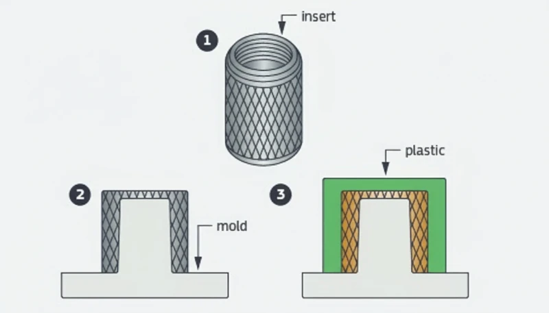
Beim Metalleinleger-Spritzgießen wird vor dem Umspritzen mit geschmolzenem Kunststoff ein vorgeformtes Metallteil in die Kavität eingelegt. Das Ergebnis ist eine dauerhaft verbundene Baugruppe, die Leitfähigkeit, Gewindefestigkeit und Steifigkeit von Metall mit Gestaltungsfreiheit und geringem Gewicht von Kunststoff verbindet.
Die Abgrenzung zum Mehrkomponenten-Umspritzen1 ist wichtig: Dabei wird ein zweiter Kunststoff auf ein erstes Kunststoffsubstrat gespritzt. Beim Einlegespritzgießen2 wird dagegen vor Zyklusbeginn ein vorgefertigtes Teil – fast immer Metall, gelegentlich Keramik oder ein vorgeformtes Bauteil – in die Kavität gelegt. Der Metalleinsatz wird von Hand, einem Roboterarm oder einer automatischen Vibrationszuführung bestückt. Nach korrekter Positionierung schließt die Form; Kunststoffschmelze umfließt den Einsatz und verankert ihn in der endgültigen Bauteilgeometrie. Dieser einstufige Prozess ersetzt nachgelagerte Montagen wie Einpressen, Ultraschallschweißen oder Kleben und senkt Kosten sowie Ausfallrisiko.
In unserem Werk in Shanghai betreiben wir 47 Spritzgießmaschinen von 90T bis 1850T, was uns die Flexibilität gibt, Einsatzspritzgießaufträge von empfindlichen M1.0 Elektronikeinsätzen bis hin zu schweren Automobilbuchsen zu bearbeiten.
"Umspritzte Gewindeeinsätze halten 5–10× mehr Montagezyklen stand als selbstschneidende Schrauben in Kunststoffdomen."True
Selbstschneidende Schrauben schneiden bei jedem Einschrauben Gewinde in den Kunststoff und schädigen dadurch zunehmend das Material des Doms. Eingespritzte Messinggewinde verteilen die Last über den vollständigen Eingriff des Metallgewindes und halten die Klemmkraft über Hunderte Montagezyklen aufrecht, ohne dass das Gewinde ausreißt.
"Die Zykluszeiten beim Umspritzen von Einlegeteilen sind stets erheblich länger als bei Standard-Spritzgießzyklen."False
Bei automatisierter Bestückung mit Einlegeteilen beträgt die zusätzliche Zeit häufig nur 3–5 Sekunden pro Zyklus. Einspritz-, Nachdruck- und Kühlphase sind nahezu identisch mit dem Standardspritzgießen. Bei Automobilsteckverbindern in Großserie sind Zykluszeiten von 18–22 Sekunden einschließlich Einlegeteilplatzierung erreichbar.
Wie funktioniert das Umspritzen von Metalleinsätzen?
Das Spritzgießverfahren3 für Einlegeteile folgt demselben Grundzyklus wie das Standardspritzgießen, besitzt aber einen entscheidenden Vorschritt: Das Metallteil wird in die Kavität eingelegt. Nachfolgend ist der vollständige Ablauf schrittweise dargestellt.
Schritt 1: Vorbereitung des Einlegeteils
Bevor Kunststoff fließt, müssen die Metalleinsätze sauber, trocken und frei von Bearbeitungsölen oder Oberflächenverunreinigungen sein. Viele Betriebe reinigen Einsätze in einem Ultraschallbad oder Lösungsmitteltauchbad und trocknen sie anschließend mit Heißluft. Verunreinigungen auf der Einsatzoberfläche wirken wie Trennmittel und zerstören die mechanische Verbindung zwischen Metall und Kunststoff.
Bei einigen Anwendungen müssen die Einlegeteile auf 80–120 °C vorgewärmt werden. Das Vorwärmen verringert den Temperaturunterschied zwischen dem geschmolzenen Kunststoff und dem kalten Metall. Dadurch werden Restspannungen an der Grenzfläche minimiert und ein vorzeitiges Erstarren verhindert, das andernfalls eine schwache Bindenaht erzeugen würde. Das Vorwärmen ist besonders bei stark schwindenden Werkstoffen wie Polyamid und Polypropylen wichtig.
Schritt 2: Einsatz platzieren
Das Werkzeug öffnet sich, und der Einleger wird an seiner vorgesehenen Position auf der Kavitätsseite des Werkzeugs platziert. Bei Kleinserien legen Bediener die Einleger von Hand mit Pinzetten oder Vakuumgreifern ein. Bei Großserien platzieren Roboterarme oder automatische Zuführsysteme (Vibrationswendelförderer, Vereinzelungsmechanismen) die Einleger mit einer Positionsgenauigkeit von ±0.05 mm oder besser.
Die Formkonstruktion muss formschlüssige Halteelemente wie federbelastete Stifte, Magnettaschen oder konische Sitze enthalten, die den Einsatz beim Schließen und Einspritzen fixieren. Ohne Halterung verschiebt der Hochdruck-Schmelzestrom von typischerweise 50–150 MPa den Einsatz und erzeugt Ausschussteile.
Schritt 3: Werkzeug schließen, einspritzen und nachdrücken
Sobald der Einsatz sitzt, schließt sich die Form, und die Spritzeinheit füllt die Kavität mit geschmolzenem Kunststoff bei Temperaturen von 200 °C für Polypropylen bis 380 °C für PEEK. Die Schmelze umströmt den Einsatz und bildet jedes Oberflächenmerkmal ab. Der Nachdruck hält den Kunststoff an den Oberflächen von Kavität und Einsatz, während das Material abkühlt und schwindet.
Nachdruck und Nachdruckzeit sind beim Umspritzen von Einlegeteilen kritischer als beim Standardspritzgießen. Der Kunststoff muss lange genug unter Druck bleiben, um die Volumenschwindung um den Einsatz auszugleichen. Unzureichender Nachdruck verursacht Einfallstellen auf der dem Einsatz gegenüberliegenden Außenfläche und Hohlräume an der Metall-Kunststoff-Grenzfläche.
Schritt 4: Kühlung und Auswerfung
Die Kühlung macht 60–70% der gesamten Zykluszeit aus. Die Kühlkanäle der Form müssen sowohl dem Kunststoff als auch dem Metalleinsatz Wärme entziehen, der als thermische Masse wirkt. Bei manchen Konstruktionen ist die Wärmeleitfähigkeit des Einsatzes vorteilhaft: Messingeinsätze tragen beispielsweise dazu bei, den umgebenden Kunststoff schneller abzukühlen.
Nach dem Abkühlen öffnet sich das Werkzeug und das fertige Teil wird ausgeworfen. Auswerferstifte müssen so positioniert werden, dass sie den Einleger nicht berühren, da andernfalls Oberflächenmerkmale beschädigt oder der Einleger teilweise herausgedrückt werden könnte. Bei empfindlichen Teilen werden die Ausformung mittels Druckluft oder die robotergestützte Entnahme bevorzugt.
Welche Materialien eignen sich am besten für das Metallumspritzen?
Die Materialauswahl beim Insert-Spritzgießen umfasst zwei unabhängige Entscheidungen: das Material des Metalleinlegers und den Kunststoffträger. Die Grenzfläche zwischen beiden — die Verbindungslinie — hängt von ihrem Zusammenspiel ab.
Werkstoffe für Metalleinsätze
Messing (C36000 oder C37700) dominiert beim Einlegeteilumspritzen aus einem Grund: Es ist der beste Allround-Kompromiss. Es lässt sich leicht zu komplexen gerändelten Formen und Gewinden bearbeiten, ist ohne Beschichtung korrosionsbeständig, leitet Wärme gut, was beim Spritzgießen hilft, und kostet wesentlich weniger als Edelstahl. Bei Gewindeeinsätzen hält Messing wiederholten Montagedrehmomenten ohne Fressen oder Gewindeverformung stand.
Edelstahleinsätze (Werkstoffgüten 303, 304 oder 316) kommen in Medizinprodukten, Anwendungen mit Lebensmittelkontakt und korrosiven Umgebungen zum Einsatz, in denen Messing versagen würde. Dem stehen höhere Materialkosten, eine schwierigere Bearbeitung (wodurch der Einsatzpreis um das Zwei- bis Dreifache steigt) und eine geringere Wärmeleitfähigkeit gegenüber, die die Kühlzeit verlängert.
Aluminiumeinsätze eignen sich, wenn Gewichtsreduzierung entscheidend ist, etwa in der Luftfahrt oder bei tragbarer Elektronik. Die hohe Wärmeleitfähigkeit von Aluminium beschleunigt die Kühlung, seine geringere Härte begrenzt jedoch die Haltbarkeit von Gewinden bei wiederholter Montage. Kupfereinsätze werden in elektrischen Anwendungen eingesetzt, die maximale Leitfähigkeit erfordern—beispielsweise Stromschienen, Erdungsklemmen und Hochstromsteckverbinder.
Auswahl des Kunststoffsubstrats
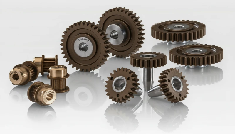
Der Kunststoff muss sowohl nach den Anwendungsanforderungen als auch nach seiner Eignung für das Umspritzen von Einlegeteilen ausgewählt werden. Materialien mit hoher Schwindung wie Polypropylen (PP) und Polyamid (PA6, PA66) erzeugen beim Abkühlen einen starken Klemmsitz auf den Einlegeteilen—verursachen an der Grenzfläche jedoch auch höhere Eigenspannungen. Ist der Wandabschnitt um den Einsatz zu dünn, können diese Spannungen Risse verursachen.
Technische Thermoplaste wie Polycarbonat (PC), PBT und PPS sind beliebte Trägerwerkstoffe beim Umspritzen von Einlegeteilen. Sie bieten geringere Schwindung von 0,4–0,7 % gegenüber 1,5–2,5 % bei PP, bessere Maßhaltigkeit und höhere Einsatztemperaturen. PEEK wird in Luft- und Raumfahrt sowie Medizintechnik eingesetzt, wenn das fertige Teil eine Autoklavsterilisation oder dauerhafte Temperaturen über 250 °C überstehen muss.
Glasfaserverstärkte Typen (PA66-GF30, PBT-GF30) sind in Strukturanwendungen verbreitet, weil Glasfasern die Schwindung verringern und die Steifigkeit um den Einsatz erhöhen. Sie wirken jedoch abrasiver auf das Werkzeug und können gehärtete Stahlkavitäten erfordern.
Mechanismus der Grenzflächenhaftung
Die Verbindung zwischen Metall und Kunststoff beim Umspritzen von Einlegeteilen ist nahezu vollständig mechanisch. Anders als beim Mehrkomponenten-Spritzgießen, bei dem die chemische Verträglichkeit zweier Kunststoffe eine molekulare Bindung erzeugen kann, bilden Metall und Thermoplast keine kovalenten Bindungen. Der Halt entsteht aus drei Quellen: Schrumpfpressung beim Abkühlen des Kunststoffs, mechanische Verzahnung mit Oberflächenmerkmalen (Rändelungen, Nuten, Hinterschneidungen) und Reibung durch die vom komprimierten Kunststoff ausgeübte Normalkraft.
"Eine Moldflow-Simulation vor der Stahlbearbeitung kann 90% der Probleme durch Einsatzverschiebung und Bindenähte verhindern."True
Die Simulation sagt voraus, wie die Schmelzefront mit dem Einlegeteil interagiert, zeigt Druckunterschiede, die eine Verschiebung verursachen, und ermittelt die Positionen von Bindenähten, bevor die Form gebaut wird. Die Korrektur der Anschnitt- oder Einlegeteilposition in der Software kostet nur einen Bruchteil der Änderung einer fertigen Form.
"Die Klebeverbindung zwischen Metall und Kunststoff liefert beim Insert-Molding die primäre Haltekraft."False
Wenn die Auszugskraft unter die Spezifikation fällt, sind die üblichen Ursachen Oberflächenverunreinigungen am Einsatz, unzureichender Packdruck und vorzeitiges Einfrieren. Öl, Fett oder Trennmittel auf der Einsatzoberfläche verhindern, dass der Kunststoff dem Rändel- oder Nutprofil folgt.
| Werkstoff | Kosten | Gewindelebensdauer | Korrosionsbeständigkeit | Wärmeleitfähigkeit |
|---|---|---|---|---|
| Messing (C36000) | Niedrig | Ausgezeichnet | Gut | Hoch (120 W/m·K) |
| Edelstahl (303/304) | Mittel-Hoch | Gut | Ausgezeichnet | Niedrig (16 W/m·K) |
| Aluminium (6061) | Mittel | Messe | Messe | Sehr hoch (167 W/m·K) |
| Kupfer (C11000) | Mittel | Messe | Messe | Am höchsten (390 W/m·K) |
| Stahl (1018) | Niedrig | Gut | Schlecht (Beschichtung erforderlich) | Mittel (50 W/m·K) |
Welche Aspekte der Werkzeugkonstruktion sind entscheidend?
Die kritischen Formdesign-Überlegungen sind die Hauptkategorien oder Optionen, die in diesem Abschnitt erklärt werden. Das Formdesign für das Einsatzspritzgießen erfordert mehr Aufmerksamkeit als eine Standardform, weil man nicht nur den Kunststofffluss, sondern auch die präzise Positionierung eines starren Metallbauteils in einer Hochdruck-, Hochtemperaturumgebung managen muss.
Positionierung und Fixierung von Einlegern
Die Kavität muss Merkmale enthalten, die den Einsatz mit einer Wiederholgenauigkeit besser als ±0,05 mm positionieren. Übliche Ansätze sind konische Aufnahmen (die den Einsatz selbst zentrieren), federbelastete Haltestifte (die den Einsatz greifen und beim Auswerfen freigeben) und Magnettaschen (für ferromagnetische Einsätze). Die Wahl hängt von der Einsatzgeometrie, dem Produktionsvolumen und der manuellen oder automatisierten Beladung ab.
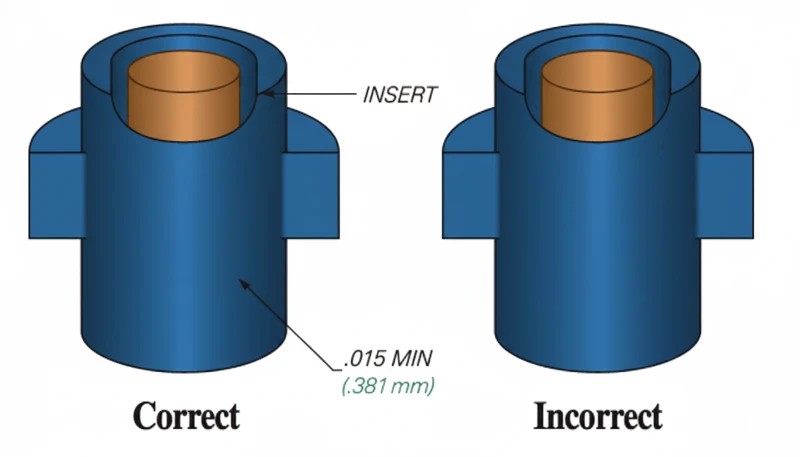
Bei Mehrkavitätenwerkzeugen muss jede Kavität identische Haltemerkmale für Einlegeteile aufweisen. Selbst kleine Unterschiede in der Setztiefe der Einlegeteile zwischen den Kavitäten führen zu uneinheitlicher Haftfestigkeit und unterschiedlichen Teilemaßen. Die Wartungspläne für das Werkzeug sollten eine regelmäßige Messung der Abmessungen der Einlegesitze vorsehen.
Anschnittposition und Schmelzefluss
Die Anschnittposition bestimmt, wie die Schmelzefront auf den Einsatz trifft und ihn umströmt. Der Anschnitt sollte die Strömung so führen, dass die Schmelze den Einsatz symmetrisch umschließt und beide Seiten annähernd gleich schnell füllt. Eine asymmetrische Füllung erzeugt einen unausgeglichenen Druck auf den Einsatz und verschiebt ihn während des Einspritzens.
Platzieren Sie den Anschnitt nicht direkt gegenüber dem Einlegeteil. Der mit hoher Geschwindigkeit auf die Oberfläche des Einlegeteils treffende Schmelzestrahl kann zwei Probleme verursachen: Er kann das Einlegeteil aus seiner Position drücken und auf der gegenüberliegenden Seite eine Fließ- oder Bindenaht erzeugen, wo sich der geteilte Schmelzestrom wieder vereinigt. Ein tangentialer Anschnitt oder Kantenanschnitt, der die Strömung an einer Seite des Einlegeteils entlangführt, ist üblicherweise zuverlässiger.
Anordnung der Kühlkanäle
Der Metalleinleger wirkt beim Abkühlen als Wärmesenke, was je nach Konstruktion hilfreich oder problematisch sein kann. Messingeinsätze kühlen den umgebenden Kunststoff schnell ab, verursachen aber auch eine ungleichmäßige Kühlung, wenn die Kühlkanäle um den Einleger nicht ausgewogen sind. Ungleichmäßige Kühlung führt zu Verzug und unterschiedlicher Schwindung.
Position der Entlüftung
Eingeschlossene Luft um Einsatzmerkmale (Rändelungen, Hinterschneidungen) erzeugt Brandstellen und schwache Bindenähte. Entlüftungen müssen an der Trennlinie und in der Nähe aller durch die Einsatzgeometrie verursachten Sackgassen im Fließweg eingeschliffen werden. Die Entlüftungstiefe sollte 0.01–0.02 mm betragen—tief genug, damit Luft entweichen kann, und flach genug, um Gratbildung zu verhindern.
Welche Konstruktionsrichtlinien gewährleisten zuverlässige Einlegeteile?
Gute Teile mit eingespritzten Einlegeteilen beginnen in der DFM-Phase. Die folgenden Richtlinien stammen aus der Produktionserfahrung mit Tausenden von Konstruktionen für Insert-Molding-Teile.
Wanddicke um Einlegeteile
Halten Sie zwischen der Außenfläche des Einsatzes und der Außenseite des Teils eine Mindestwanddicke vom 1.5-Fachen des Einsatzdurchmessers ein. Bei einem Einsatz mit 6 mm Durchmesser muss der Kunststoffdom daher einen Außendurchmesser von mindestens 9 mm haben. Bei geringerer Dicke drohen Einfallstellen an der Außenfläche und Risse durch Schwindungsspannungen. Eine größere Dicke verschwendet Material und verlängert die Kühlzeit.
Die Wand um den Einlegeteil sollte gleichmäßig sein. Unterschiedliche Wanddicken führen zu ungleichmäßiger Schwindung, wodurch der Einlegeteil aus der Mitte gezogen wird. Erfordert die Konstruktion eine nicht kreisförmige Bossengeometrie, sollte zwischen Einlegeteil und Außenwand eine konstante Dicke statt eines konstanten Außenprofils verwendet werden.
Form und Oberflächenmerkmale des Einlegeteils
Rändeln ist die häufigste Oberflächenbehandlung für runde Einsätze. Eine Kreuzrändelung bietet guten axialen Halt und Verdrehschutz. Eine Längsrändelung widersteht dem Herausziehen, aber nicht dem Verdrehen. Für maximalen Halt in beide Richtungen verwenden Sie eine Kombination aus Kreuzrändelung und einer oder mehreren Umfangsnuten.
Hinterschneidungen am Einlegeteil (etwa ein T-Kopf oder ein Flanschprofil) bieten die höchste Haltekraft, da sich der Kunststoff physisch nicht über die Hinterschneidung ziehen lässt, ohne zu versagen. Hinterschneidungen erschweren jedoch sowohl die Herstellung des Einlegeteils als auch das Auswerfen aus der Form – verwenden Sie sie nur, wenn die Anwendung eine maximale Auszugskraft erfordert.
Verdreh- und Auszugssicherung
Bei Gewindeeinsätzen ist die Verdrehsicherung entscheidend. Der Einsatz darf sich beim Ein- oder Ausschrauben einer Schraube nicht im Kunststoff drehen. Zwei Konstruktionsstrategien funktionieren: sechseckige oder quadratische Einsatzkörper, die formschlüssig im Kunststoff sitzen, und gerändelte Oberflächen für eine mechanische Verzahnung. Die Kombination beider Ansätze ist bei Anwendungen mit hohem Drehmoment am zuverlässigsten.
Eine Auszugssicherung zielt darauf ab, die Scherfläche an der Grenzfläche zwischen Einsatz und Kunststoff zu maximieren. Eine größere Eingriffslänge, breitere Nuten und Flansche mit größerem Durchmesser erhöhen die Auszugskraft. Ein typischer, gut konstruierter M3-Messingeinsatz in PA66-GF30 sollte eine Auszugskraft von 500–800 N und einen Drehmomentwiderstand von 0.5–1.0 N·m erreichen.
Toleranzkette
Das Umspritzen von Einlegeteilen führt eine zusätzliche Toleranzvariable ein: die Position des Einsatzes relativ zur Formkavität. Die endgültige Positionsgenauigkeit des Einsatzes im fertigen Bauteil hängt von der Toleranz des Formsitzes, der Fertigungstoleranz des Einsatzes und der Kunststoffschwindung ab. Planen Sie bei einer gut konstruierten und gewarteten Form ±0.1–0.2 mm für die Positionsgenauigkeit des Einsatzes ein.
Welches sind die häufigsten Fehler und wie lassen sie sich verhindern?
Die häufigsten Fehler und wie man sie verhindert, sind die Hauptkategorien oder Optionen, die in diesem Abschnitt erklärt werden. Das Einsatzspritzgießen führt zu Fehlern, die beim Standard-Spritzgießen nie auftreten. Hier sind die vier häufigsten Probleme und ihre Ursachen.
Einsatzverschiebung (Versatz)
Eine Einsatzverschiebung entsteht, wenn der Schmelzefluss die Metallkomponente aus ihrer vorgesehenen Position drückt. Die Folge sind ein außermittiger Einsatz, ungleichmäßige Wanddicke und möglicherweise freiliegendes Metall auf einer Seite. Ursachen sind unter anderem asymmetrische Anschnittplatzierung, zu hohe Einspritzgeschwindigkeit, unzureichende Fixierung des Einsatzes im Werkzeug und unausgeglichener Fluss in Mehrkavitätenwerkzeugen.
Lösungen: Verwenden Sie eine Formfüllsimulation, um eine ausgewogene Füllung um jeden Einleger zu überprüfen. Reduzieren Sie in der ersten Stufe die Einspritzgeschwindigkeit, um den dynamischen Druck auf den Einleger zu senken. Verbessern Sie die Haltemerkmale im Werkzeug – ersetzen Sie Schwerkraftauflagen durch federbelastete Stifte oder konische Presspassungen. Balancieren Sie bei Mehrkavitätenwerkzeugen das Angusssystem so aus, dass alle Kavitäten mit derselben Geschwindigkeit gefüllt werden.
Einfallstellen und Hohlräume
Einfallstellen treten auf der Teiloberfläche gegenüber einem dicken Einsatz auf, weil die große thermische Masse langsam abkühlt und der Kunststoff von der Kavitätswand wegschwindet. Im Inneren entstehen Hohlräume, wenn die Außenhaut erstarrt, bevor der Kern vollständig nachverdichtet ist.
Lösungen: Erhöhen Sie den Nachdruck und verlängern Sie die Nachdruckzeit, um die Volumenschwindung um den Einsatz auszugleichen. Wärmen Sie die Einsätze vor, um den Temperaturgradienten zu verringern. Halten Sie eine Mindestwanddicke vom 1.5×-Fachen des Einsatzdurchmessers ein. Erwägen Sie bei sehr dicken Domen den Einsatz eines Treibmittels (Mikrozellschaumspritzgießen).
Geringe Verbundfestigkeit
Wenn die Auszugskraft unter die Spezifikation fällt, sind die üblichen Ursachen Oberflächenverunreinigungen am Einsatz, unzureichender Nachdruck und vorzeitiges Einfrieren. Öl, Fett oder Trennmittel auf der Einsatzoberfläche verhindert, dass sich der Kunststoff an das Rändel- oder Nutprofil anlegt.
Door-Module, Fahrgestell
Bauteilverzug und Rissbildung
Unterschiedliche Schwindung zwischen dem durch Metall eingeschränkten Einsatzbereich und den frei schwindenden Kunststoffwänden verursacht Verzug. In Extremfällen übersteigt die Restspannung um den Einsatz die Zugfestigkeit des Kunststoffs und führt zu radialen Rissen in der Domwand.
Lösungen: Einen Werkstoff mit geringerer Schwindung oder eine glasfaserverstärkte Qualität verwenden. Den Einleger vorwärmen, um den Temperaturschock zu verringern. Den Dom mit gleichmäßiger Wanddicke auslegen und zur strukturellen Abstützung Verstärkungsrippen ergänzen. Das Tempern des Fertigteils bei einer Temperatur unterhalb der Wärmeformbeständigkeitstemperatur des Kunststoffs kann Eigenspannungen abbauen, ohne das Teil zu verformen.
Wie werden Baugruppen aus dem Insert-Molding geprüft und validiert?
Die Qualitätsvalidierung von Insert-Molding-Teilen geht über die übliche Maßprüfung hinaus. Die Metall-Kunststoff-Grenzfläche erfordert spezielle mechanische Prüfungen, um nachzuweisen, dass die Verbindung die Anwendungsanforderungen erfüllt.
Auszugprüfung
Eine Universalprüfmaschine spannt das Kunststoffteil ein und bringt eine axiale Kraft auf, um den Einsatz herauszuziehen. Die Prüfung misst die maximale Auszugskraft und erfasst die Versagensart—ob der Kunststoff bricht, sich der Einsatz aus der Rändelung löst oder der Kunststoffdom reißt. Ein gut ausgelegter M3-Messingeinsatz in glasfaserverstärktem Nylon sollte dauerhaft eine Auszugskraft von 500–800 N erreichen.
Auszugprüfungen sollten zu Produktionsbeginn an Mustern aus jeder Kavität und anschließend regelmäßig während des Laufs durchgeführt werden. Ein Rückgang der Auszugskraft um 10–15% gegenüber den ersten Mustern signalisiert eine Prozessdrift — typischerweise eine steigende Werkzeugtemperatur, einen Materialabbau oder verschlissene Einsatzsitze.
Drehmomentprüfung
Bei Gewindeeinsätzen dreht ein kalibrierter Drehmomentschlüssel eine Schraube in den Einsatz, bis entweder das vorgegebene Einbaudrehmoment erreicht ist oder sich der Einsatz im Kunststoff dreht. Das Drehmoment bis zum Versagen legt das maximale sichere Betriebsdrehmoment fest — für Produktionsspezifikationen wird es üblicherweise auf 50–60 % des Versagensdrehmoments festgelegt.
Drehmomentprüfungen erkennen Probleme, die bei Auszugsprüfungen unentdeckt bleiben. Ein Einleger kann dank tiefer Rändelung eine hervorragende axiale Haltekraft aufweisen, aber einen geringen Verdrehwiderstand haben, wenn das Rändelmuster zu fein ist oder der Kunststoff die Rillen nicht vollständig ausgefüllt hat.
Querschnittsanalyse
Durch das Auftrennen eines Teils mit eingespritztem Einlegeteil und die vergrößerte Untersuchung der Schnittfläche lässt sich die Qualität der Verbindungsgrenzfläche beurteilen. Achten Sie auf Hohlräume zwischen Einsatz und Kunststoff, unvollständig gefüllte Rändelnuten und Einfallstellen an der Außenfläche. Die Querschnittsanalyse ist zerstörend und wird typischerweise während der anfänglichen Prozessqualifizierung sowie nach Werkzeugänderungen durchgeführt.
Umwelt- und Lebensdauerprüfung
Temperaturwechselprüfungen (typischerweise -40 °C bis +85 °C oder höher, je nach Anwendung) zeigen, ob unterschiedliche Ausdehnung von Metall und Kunststoff die Bindung im Laufe der Zeit schwächt. Thermoschockprüfungen mit schnellen Temperaturübergängen sind besonders aggressiv: Sie legen jede schwache Bindenaht innerhalb von 50–100 Zyklen offen.
Feuchtigkeitseinwirkung ist bei hygroskopischen Materialien wie Nylon relevant. Nach 48 Stunden bei 85% RH und 85 °C nimmt Nylon genug Feuchtigkeit auf, um um 0.5–1.0% zu quellen, wodurch sich der Druckhalt am Einleger um 15–25% verringern kann. Prüfen Sie stets unter realistischen Einsatzbedingungen.
Wo wird Metalleinlegerspritzgießen branchenübergreifend eingesetzt?
Das Umspritzen von Metalleinsätzen eignet sich für jede Branche, die feste, zuverlässige Metall-Kunststoff-Verbindungen benötigt. Die vier größten Anwendungsbereiche sind die Automobilindustrie, die Elektronik, Medizinprodukte und Konsumgüter.
Im Automobilbereich finden sich umspritzte Gewindeeinsätze in Innenverkleidungen, Gehäusen von Instrumentengruppen, Sensorgehäusen und elektrischen Steckverbindern im Motorraum. Ein einzelner Mittelklassewagen enthält 50–100 umspritzte Gewindedome. Automobilzulieferer legen für jeden Einsatz Auszugs- und Drehmomentwerte fest, und Produktionsteile müssen Stichproben der statistischen Prozessregelung bestehen, um die PPAP-Dokumentation aufrechtzuerhalten.
Zu den Elektronikanwendungen gehören PCB-Montagedome, Haltestifte für HF-Abschirmungen, Batterieklemmenblöcke und Steckverbindergehäuse.
Der Trend zur Miniaturisierung hat die Nachfrage nach Einsätzen bis hinunter zu M1.0 erhöht. Dafür sind Präzisionswerkzeuge mit Einsatzaufnahmen mit 0.01 mm Toleranz und eine spezialisierte Bestückungsautomatisierung erforderlich.
Hersteller von Medizinprodukten verwenden Einlegespritzgießen für Instrumentengriffe, Komponenten chirurgischer Werkzeuge und Gehäuse diagnostischer Geräte. Edelstahleinsätze sind in diesem Bereich Standard, weil sie die Autoklavsterilisation überstehen und Biokompatibilitätsanforderungen erfüllen. Qualitätssysteme nach ISO 13485 verlangen die vollständige Rückverfolgbarkeit jeder Einsatzcharge bis zum fertigen Produkt.
Konsumgüter — Gehäuse für Elektrowerkzeuge, Küchengeräte, Sportausrüstung und Spielzeug — nutzen Insert-Molding für Gewindeverbindungen, die wiederholtes Zerlegen und Zusammenbauen überstehen müssen. Der Mehrpreis eines Messingeinsatzes (bei großen Mengen üblicherweise $0.02–$0.10 pro Stück) ist gegenüber den Garantiekosten eines ausgerissenen Kunststoffgewindes unbedeutend.
Über diese vier Sektoren hinaus findet sich Einlegerspritzgießen in Telekommunikationshardware (Ferrulen für Glasfasersteckverbinder, Antennenhalterungen für Basisstationen), Industrieausrüstung (Ventilkörper, Aktuatorgehäuse, Sensorhalterungen) und Verteidigungsanwendungen, bei denen Metall-Kunststoff-Gewindeverbindungen den in MIL-STD-Normen festgelegten Stoß- und Vibrationsbelastungen standhalten müssen. Neue EV-Batterieanwendungen nutzen umspritze Befestigungsdome aus Edelstahl für die strukturelle Befestigung und elektrische Erdung.
Ingenieure, die Fügeverfahren bewerten, vergleichen das Umspritzen von Einlegeteilen häufig mit drei Alternativen. Jede weist eigene Stärken und Grenzen auf.
Insert Molding gegenüber Overmolding
Beim Insert-Molding wird eine starre, vorgefertigte Komponente (meist Metall) mit Kunststoff umschlossen. Beim Overmolding wird ein zweiter Kunststoff über ein erstes Kunststoffsubstrat gespritzt, wodurch ein Soft-Touch-Griff, eine Dichtung oder ein mehrfarbiges Teil entsteht. Sind die beiden Kunststoffe kompatibel (zum Beispiel TPE auf PP), kann beim Overmolding eine chemische Verbindung zwischen ihnen entstehen. Insert-Molding beruht vollständig auf mechanischer Verankerung. Wählen Sie Insert-Molding, wenn Sie Metalleigenschaften benötigen; wählen Sie Overmolding, wenn Sie mehrere Kunststoffmaterialien integrieren müssen.
Outsert Molding ist die Umkehrung des Insert Molding: Dabei werden Kunststoffmerkmale auf ein flaches Metallsubstrat gespritzt, anstatt Metall in Kunststoff einzulegen. Beim Ultraschalleinsetzen wird ein Metalleinsatz in einem Sekundärvorgang mithilfe hochfrequenter Schwingungen in einen vorgeformten Kunststoffdom eingetrieben. Beide Verfahren vermeiden die Werkzeugkomplexität des Insert Molding, gehen jedoch zulasten der Gleichmäßigkeit und Festigkeit der Verbindung.
Der entscheidende Kompromiss: Umspritzen erzeugt stärkere, gleichmäßigere Verbindungen, weil sich der Kunststoff unter kontrolliertem Druck und kontrollierter Temperatur gleichmäßig um das Einlegeteil legt. Beim Ultraschalleinsetzen hängt die Verbindung während eines kurzen Zyklus von 0,5–2 Sekunden von Schwingungsamplitude, Einsetztiefe und Kunststoffschmelze ab—mehr Variablen und mehr Möglichkeiten für Abweichungen.
Häufig gestellte Fragen zum Spritzgießen mit Metalleinlegern
Wie groß ist die Mindestwanddicke um einen Metalleinleger beim Spritzgießen?
Der übliche Ausgangspunkt ist mindestens das 1,5-fache des Einsatzdurchmessers als Kunststoffwand um den Metalleinsatz herum, mit mehr Spielraum für spröde oder glasgefüllte Harze. Die Wand muss auch um den Bund herum gleichmäßig bleiben. Wenn eine Seite dünn und die gegenüberliegende Seite dick ist, wird die Schrumpfung beim Abkühlen ungleichmäßig und das Risiko von Rissen steigt. Für lasttragende Gewinde bestätigen Sie die Wand mit Auszieh- und Drehmomenttests, anstatt sich während der Musterherstellung nur auf einen Handbuchwert zu verlassen. Bestätigen Sie die Wahl mit Produktionsmusterdaten.
Können beim Umspritzen von Einlegeteilen Aluminium- statt Messingeinsätze verwendet werden?
Ja, aber Aluminium ist nicht in jedem einsatzgespritzten Teil ein direkter Ersatz für Messing. Aluminium reduziert das Gewicht und verbessert die Wärmeübertragung, ist jedoch weicher, verformt sich leichter während des Beladens und bietet normalerweise eine geringere Gewindebeständigkeit. Verwenden Sie es für leichte Gehäuse, tragbare Geräte oder Luft- und Raumfahrtteile, bei denen die Masse wichtig ist. Für wiederholte Schraubmontage ist Messing oder Edelstahl normalerweise sicherer, es sei denn, Tests beweisen, dass der Aluminiumeinsatz unter realer Belastung und Temperatur den Drehmoment- und Auszugsanforderungen entspricht. Bestätigen Sie die Wahl mit Produktionsmusterdaten.
Wie genau ist die Positionierung von Einlegeteilen in umspritzten Bauteilen?
Typische Produktionsgenauigkeit der Einsatzpositionierung kann etwa plus/minus 0,05 bis 0,10 mm betragen, wenn die Form positive Einsatzsitze, stabile Beladung und kontrolliertes Schließen aufweist. Engere Toleranzen sind möglich, hängen aber von der Einsatz-Toleranz, der Wiederholgenauigkeit des Laders, dem Schmelzdruck und dem Kavitätenausgleich ab. Beurteilen Sie die Genauigkeit nicht allein anhand von CAD-Daten. Validieren Sie sie mit Erstmuster-CMM-Prüfungen und wiederholten Prüfungen über jede Kavität hinweg, da ein schwacher Halter eine Abweichung verursachen kann, die erst nach dem Aufheizen des Werkzeugs auftritt. Bestätigen Sie die Wahl mit Produktionsstichprobendaten.
Funktioniert Einlegespritzgießen mit Hochtemperaturkunststoffen wie PEEK?
Ja, Einsatzspritzgießen kann mit Hochtemperaturkunststoffen wie PEEK, PPS, PEI und Hochtemperatur-Nylon funktionieren, aber das Einsatzteil und das Formdesign müssen viel höhere Verarbeitungstemperaturen bewältigen. Das Metall-Einsatzteil muss möglicherweise vorgewärmt werden, damit die Schmelze nicht zu schnell um die Rändelung oder Nut erstarrt. Der Lieferant benötigt auch Werkzeugstahl, Heißkanal- und Trocknungssteuerungen, die für das Harz geeignet sind. Führen Sie für kritische Teile einen materialspezifischen Versuch durch, bevor Sie sich für Produktionswerkzeuge und endgültige Abmessungen entscheiden. Bestätigen Sie die Wahl mit Produktionsstichprobendaten.
Warum reißen umspritzte Teile im Bereich des Doms?
Risse um den Ansatz herum entstehen meist durch Eigenspannungen, ungleichmäßige Wandstärke, scharfe Ecken in der Nähe des Einsatzes oder einen großen Temperaturunterschied zwischen dem kalten Einsatzteil und der heißen Kunststoffschmelze. Hochschrumpfende Materialien verschlimmern das Problem, weil sich der Kunststoff zusammenziehen möchte, während das Metall-Einsatzteil die Bewegung behindert. Die üblichen Lösungen sind gleichmäßige Wandstärke, großzügige Radien, glasfaserverstärktes oder schrumpfarmes Harz, Vorwärmen des Einsatzes und Validierung durch thermisches Zyklieren anstatt nur Raumtemperaturprüfung vor Versand und Freigabe. Bestätigen Sie die Wahl mit Produktionsstichprobendaten.
Wie viele Einlegeteile können in ein einzelnes Teil eingeformt werden?
Ein Teil kann einen oder viele Einsätze enthalten, aber die praktische Grenze wird durch die Ladegenauigkeit, die Zykluszeit, den Kavitätenzugang und das Risiko falsch geladener Hardware bestimmt. Manuelles Laden ist normalerweise am besten für geringe Stückzahlen oder einfache Teile mit ein bis drei Einsätzen. Roboterladen wird attraktiver, wenn die Anzahl der Einsätze steigt, die Ausrichtung wiederholbar sein muss oder Arbeiterermüdung Fehler verursacht. Jeder zusätzliche Einsatz sollte einen positiven Sitz und ein klares Poka-Yoke-Merkmal im Formdesign haben. Bestätigen Sie die Wahl mit Produktionsstichprobendaten.
Ist das Umspritzen von Einlegeteilen für die Kleinserienfertigung geeignet?
Einsatzspritzgießen kann für die Kleinserienfertigung geeignet sein, wenn das Bauteil zuverlässige Festigkeit, eine dichte Metall-Kunststoff-Integration oder eine wiederholbare Positionierung benötigt, die eine nachträgliche Einbringung nicht leisten kann. Für einfache Gewindebunde unter einigen hundert Teilen ist es möglicherweise nicht wirtschaftlich, da die Form Einsatzsitze und zusätzliche Musterarbeit erfordert. Für Prototypen oder Brückenläufe vergleichen Sie drei Wege: manuelles Einsatzspritzgießen, Ultraschalleinbringung nach dem Spritzgießen sowie spanende Bearbeitung plus Montage. Wählen Sie basierend auf dem Gesamtrisiko, nicht nur auf den Werkzeugkosten für den Käufer. Bestätigen Sie die Wahl mit Produktionsmusterdaten.
Umspritzen: Beim Umspritzen handelt es sich um ein Zweikomponenten-Spritzgussverfahren, bei dem ein zweiter Kunststoff über ein erstes Substrat gespritzt wird, um ein Bauteil aus mehreren Materialien oder in mehreren Farben herzustellen. ↩
Einlegespritzgießen: Das Einlegespritzgießen ist ein Fertigungsverfahren, bei dem ein vorgeformtes Bauteil in die Kavität eines Spritzgießwerkzeugs eingelegt und mit geschmolzenem Kunststoff umschlossen wird, sodass eine einzige integrierte Baugruppe entsteht. ↩
Spritzgießverfahren: Das Spritzgießverfahren ist ein zyklisches Fertigungsverfahren, bei dem Kunststoffgranulat geschmolzen, unter Druck in eine Formkavität eingespritzt, abgekühlt und als festes Bauteil ausgeworfen wird. ↩