 Ir al contenido

- Cooling accounts for 50-70% of total injection molding cycle time; optimizing it is the fastest way to reduce cost.
- The six main cooling channel types are: straight-line, baffle, bubbler, spiral, conformal, and thermal pin.
- Water cooling at 10-25 degrees C is the industry standard for most thermoplastics; oil cooling is used above 80 degrees C.
- Conformal cooling channels reduce cycle time by 20-35% compared to conventional straight channels.
- Channel diameter, pitch, and distance from cavity wall directly determine cooling uniformity and warp risk.
- In our factory, we use mold flow analysis on every new mold to verify temperature uniformity before cutting steel.
¿Qué es un Sistema de Enfriamiento de Molde de Inyección?
An injection mold cooling system is a network of channels, passages, and temperature-control devices machined into the mold that remove heat from molten plastic after injection, reducing duración del ciclo1 by 50-70% and ensuring dimensional accuracy. Without a properly designed cooling system, parts warp, sink marks appear, and production throughput collapses. The cooling system is not an afterthought — it determines whether your mold is profitable or a liability.
Cooling works by circulating a temperature-controlled medium — most commonly water at 10-25 degrees C — through channels drilled or printed into the mold plates surrounding the cavity. Heat from the molten plastic (injected at 180-320 degrees C depending on material) transfers into the coolant, which carries it away to an external chiller or cooling tower. The part reaches ejection temperature (typically 40-80 degrees C below the material glass transition temperature) and is removed.
In our factory in China, we run 47 injection molding machines across 3 workshops. Every mold we build receives a dedicated cooling circuit layout during DFM2 review, and we use análisis del flujo de moldes3 to simulate temperature distribution before any steel is machined. This discipline is why our first-pass approval rate exceeds 92%.
Why Cooling System Design Matters: The Numbers
Cooling phase accounts for 50-70% of total cycle time in standard thermoplastic injection molding. A 10-second reduction in cooling time on a 30-second cycle translates to a 33% increase in throughput — producing hundreds of thousands more parts per year on the same machine with zero capital investment. That is the single highest-ROI optimization available in injection molding.
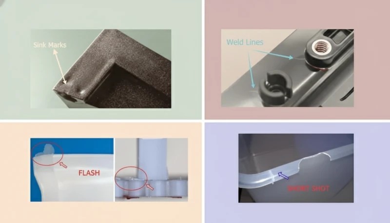
Poor cooling design creates five interconnected problems: warping and dimensional deviation from uneven temperature gradients above 5 degrees C across the cavity surface; sink marks from insufficient cooling time causing premature ejection; internal residual stress from rapid or uneven solidification; surface defects including gloss variation and blush; and extended cycle times from conservative cooling settings to compensate for poor channel placement.
All five problems cost money — either through scrap, rework, slow cycles, or failed customer inspections. In our experience reviewing hundreds of mold projects, poor cooling design is the most common root cause of first-article failures. Customers often attribute failures to material or machine settings when the actual cause is a cooling circuit that was never properly designed.
| Parámetro | Poor Cooling | Optimized Cooling | Improvement |
|---|---|---|---|
| Duración del ciclo | 35 sec | 22 segundos | -37% |
| Temperature uniformity | >10°C delta | <3°C delta | 3x better |
| Warp (typical ABS part) | 0.8 mm | 0.15 mm | 81% reduction |
| Sink mark depth | 0.3 mm | <0.05 mm | 6x better |
| Annual throughput (1 cavity) | 825,000 shots | 1,310,000 shots | +59% |
These figures come from our engineering team’s internal benchmarking data across 200+ mold projects. The exact numbers vary by material, wall thickness, and part geometry — but the directional impact is consistent: every second of cooling time saved translates directly to cost reduction and capacity increase.
6 Types of Injection Mold Cooling Systems
Injection molds use six primary cooling channel configurations, each suited to different part geometries, precision requirements, and budget constraints. Understanding when to use each type is foundational to mold design.
1. Straight-Line Cooling Channels
Straight-line (or drilled) cooling channels are the standard for flat or simple-geometry parts, created by drilling 6-14 mm diameter holes through mold plates in a grid or parallel pattern. Channel-to-cavity distance is typically 15-25 mm for P20 steel molds, with 1.5 times channel diameter as minimum wall thickness to the cavity surface. Coolant flow rate targets turbulent flow (Reynolds number above 10,000), which transfers heat 3-5 times more efficiently than laminar flow.
Straight channels are the most cost-effective option — drilling costs $50-200 per circuit versus $500-5,000 for conformal channels — and are fully appropriate for flat lids, panels, housings with uniform wall thickness, and commodity parts. Their limitation is geometric: they cannot follow curved or complex cavity surfaces, leaving hot spots in corners and ribs where the channel is necessarily further from the cavity wall.
2. Baffle Cooling
Baffles are thin metal plates inserted into drilled channels that force coolant to flow down one side and back up the other, converting a single straight hole into a U-shaped flow path. They are used in narrow cores, pins, and areas where two parallel channels cannot be drilled side by side. A typical baffle doubles the cooling surface area in a restricted zone without requiring additional channel ports.
Baffle effectiveness depends on plate clearance (0.05-0.15 mm on each side) and coolant flow velocity. We typically specify baffles for any core diameter between 16 and 40 mm. Below 16 mm, thermal pins or bubblers are more effective; above 40 mm, spiral channels become the preferred option. The combination of baffle geometry and proper flow rate is what makes the difference between adequate and excellent core cooling.
3. Bubbler Cooling
Bubblers (also called fountain cooling) use a small-diameter inner tube inserted into a blind hole: coolant flows down the inner tube and returns up the annular space between the tube and hole wall. This creates a spray effect at the tip of the core — the hottest zone — achieving very high local heat transfer coefficients. Bubblers are standard for cores under 16 mm in diameter and deep pin features with aspect ratios above 4:1.
In our shop, we use bubblers on every core pin above 25 mm height, regardless of diameter. The additional machining cost of $30-80 per bubbler port is consistently recovered in cycle time reduction at the mold trial. For cores that are too small for bubblers, beryllium copper inserts provide passive heat conduction to nearby water channels.
4. Spiral (Helix) Cooling Channels
Spiral cooling channels wrap a helical path around cylindrical cores or circular cavities, providing uniform cooling over 360 degrees of the feature. For threaded closures, round containers, medical vials, and any rotationally symmetric part, spiral channels reduce peak-to-average temperature differential from more than 8 degrees C (with straight channels) to less than 2 degrees C.
Pitch and lead angle are tuned to the coolant flow rate — typically 4-8 mm pitch with a 45-degree helix angle for water cooling. Spiral inserts can be machined as separate components and pressed into mold cores, making them replaceable when worn or when geometry changes require a redesign.
5. Conformal Cooling Channels
conformal cooling4 channels follow the exact 3D contour of the mold cavity wall at a uniform standoff distance (typically 5-12 mm), made possible by metal additive manufacturing (DMLS or SLM). Where conventional drilled channels leave hot spots on curved surfaces and sharp corners, conformal channels maintain cavity-to-channel distance within plus or minus 1 mm across the entire surface — delivering 20-35% cycle time reduction and dramatically more uniform cooling.
The trade-off is cost and lead time: a conformal-cooled insert produced by DMLS from H13 tool steel costs $3,000-15,000 versus $500-2,000 for a conventionally machined insert. The break-even point is typically reached at 50,000-100,000 shots for high-volume parts, where cycle time savings translate to machine-hour savings that exceed the tooling premium. For medical devices, automotive trim, and consumer electronics at high volume, conformal cooling is the standard of practice.
6. Thermal Pins and Heat Pipes
Thermal pins (heat pipes) are sealed copper or beryllium copper components charged with a phase-change fluid. They passively transfer heat from hot spots — sharp corners, ribs, thin features — to a water-cooled heat sink with no active coolant flow. Heat pipe thermal conductivity reaches 10,000-100,000 W/m·K, compared to 20-50 W/m·K for P20 steel.
Thermal pins are ideal for features too small or inaccessible for active cooling channels, such as ribs under 3 mm wide or ejector pin areas. They require no plumbing connections and can be retrofitted into existing molds without major rework. In our factory, thermal pins have eliminated hot-spot sink marks on several medical device molds where ribs could not otherwise be adequately cooled.
Cooling Medium Comparison: Water, Oil, and Air
The cooling medium choice — water, oil, or air — determines heat transfer capacity, operating temperature range, maintenance requirements, and cost. Each medium fits a specific window of mold temperature requirements, and choosing the wrong medium creates quality problems that are surprisingly difficult to trace back to their root cause.
| Medio | Temp Range | Heat Transfer | Lo mejor para | Mantenimiento |
|---|---|---|---|---|
| Water (chilled) | 10-60°C | High (3,000-10,000 W/m2K) | Most thermoplastics (PE, PP, ABS, PC) | Scale/corrosion control |
| Water (tower) | 25-35°C | Alta | High-volume commodity parts | Algae and mineral control |
| Oil (thermal) | 60-200°C | Medium (500-2,000 W/m2K) | High-temp materials (PEI, PEEK, PPS) | Fluid replacement every 12 months |
| Aire | Ambient | Low (50-200 W/m2K) | Thin walls, elastomers, foam parts | Minimal — filter cleaning only |
| Beryllium copper | Passive | Very high (conduction) | Thin ribs, micro features | None |
In our factory, 90% of molds run water cooling at 15-25 degrees C using a closed-loop chiller system. For engineering resins processed above 120 degrees C (PEI, PEEK, PPS, POM), we switch to temperature-controlled oil circuits that maintain mold temperature at 80-160 degrees C. Air cooling is reserved for simple silicone and thin-wall foam applications where water channel proximity would cause surface condensation.
Water chemistry management is a critical and often overlooked aspect of mold cooling. We use deionized water with pH 7-8 and a corrosion inhibitor package in all production chiller loops. Tap water causes progressive scale buildup that reduces heat transfer by 15-25% per millimeter of deposit — an invisible performance degradation that shows up as gradually increasing cycle times over 12-18 months of production.
True or False: Injection Mold Cooling Myths
“Cooling time accounts for more than half of total injection molding cycle time.”Verdadero
In most standard thermoplastic applications, cooling accounts for 50-70% of total cycle time. A 30-second cycle typically breaks down as: injection 3-5 sec, pack/hold 5-8 sec, cooling 15-22 sec, and ejection/mold-open 3-5 sec. Optimizing the cooling phase is the single highest-leverage action in cycle time reduction. Even a 20% improvement in cooling efficiency on a 20-second cooling window saves 4 seconds — a 13% cycle time reduction with no other changes.
“Using colder water always produces faster, better results in injection mold cooling.”Falso
Dropping coolant temperature below the dew point causes condensation on the mold surface — forming water droplets that transfer to part surfaces as cosmetic defects, accelerate mold surface rust, and cause short shots. For hygroscopic materials like nylon and ABS, mold temperature must stay above 15 degrees C to prevent moisture-related defects. The optimal coolant temperature depends on material, wall thickness, ambient humidity, and surface finish requirements — not simply the lowest achievable temperature.
These two principles — that cooling dominates cycle time and that coolant temperature must be carefully controlled — form the foundation of effective injection mold cooling system engineering. Misunderstanding either one leads to wasted machine time or cosmetic defects that fail customer inspection. The next two myths address more advanced design decisions around coolant flow dynamics and cooling technology selection. Both are frequently misapplied in practice: engineers either accept laminar flow as unavoidable or invest in conformal cooling for parts that do not justify the premium. Getting the analysis right saves both time and money.
“Turbulent coolant flow transfers heat significantly more efficiently than laminar flow.”Verdadero
Turbulent flow (Reynolds number above 10,000) achieves convective heat transfer coefficients of 3,000-10,000 W/m2K, compared to 500-1,500 W/m2K for laminar flow — a 3-5 times improvement in heat transfer rate. Achieving turbulence requires minimum flow velocities of 0.5-1.0 m/s for 8 mm channels. We specify flow rate requirements on every mold cooling circuit drawing and verify turbulent conditions at the mold trial using digital flow meters on each circuit port.
“Conformal cooling channels always justify their higher cost over conventional straight channels.”Falso
Conformal cooling is a premium solution justified only by high production volumes and geometrically complex parts. For flat panels, lids, and simple boxes running under 50,000 shots annually, the $10,000-30,000 DMLS tooling premium will never be recovered through cycle time savings. The break-even analysis must account for machine hourly rate, cycle time delta, annual volume, and tool life. For low-volume specialty parts, optimized straight channels deliver 90% of the benefit at 10% of the cost.
Key Design Parameters for Injection Mold Cooling
Five engineering parameters govern cooling system performance. Getting these right at the design stage prevents expensive rework after mold trials. These numbers are not arbitrary — they emerge from decades of empirical testing and thermal simulation validation.
Channel Diameter
Standard cooling channel diameters range from 6 mm (small precision molds) to 16 mm (large structural molds). The most common sizes in our shop are 8 mm and 10 mm, which balance drilling cost, flow resistance, and heat transfer surface area. Channels below 6 mm are prone to blockage from scale and corrosion and require filtered deionized water; channels above 16 mm reduce structural mold strength and increase the risk of channel-to-channel breakthrough during drilling.
Channel-to-Cavity Distance
Channel centerline-to-cavity surface distance should be 1.5-2 times the channel diameter for balanced thermal and structural performance. For an 8 mm channel in P20 steel, the target distance is 12-16 mm. Closer placement increases cooling rate but risks stress cracking and core breakthrough; greater distances reduce cooling efficiency and create hot spots between channels where the thermal gradient is not adequately controlled.
Channel Pitch (Center-to-Center Spacing)
Pitch between parallel channels affects temperature uniformity across the cavity surface. The standard recommendation is 3-5 times the channel diameter. For 10 mm channels, a pitch of 30-50 mm balances thermal uniformity against drilling cost. Wider pitch produces temperature ripple between channels; tighter pitch is structurally challenging and increases the mold plate cost.

Coolant Flow Rate and Reynolds Number
Flow rate must achieve Reynolds number above 10,000 for turbulent flow. For an 8 mm channel, this requires flow velocity above 0.7 m/s, corresponding to approximately 2.6 liters per minute per circuit. Our standard practice is to verify flow rate at the mold trial using digital flow meters installed on each circuit port, and record actual Reynolds numbers in the mold setup sheet for future production reference.
Inlet and Outlet Temperature Differential
Coolant inlet-to-outlet temperature rise should stay below 3-5 degrees C per circuit. A larger delta indicates insufficient flow rate — the coolant is absorbing too much heat per pass — and creates a temperature gradient along the channel length that results in non-uniform cooling from one end of the part to the other. We target a delta below 3 degrees C as our standard and adjust flow rate at trial until this is achieved.
Step-by-Step Cooling System Design Process
Our engineering team follows a structured seven-step process for every new mold cooling system, from initial CAD review through mold trial validation. This process eliminates most cooling-related first-article failures before they happen.
Step 1 is thermal load calculation: estimate heat input from the injected plastic mass, material enthalpy, and cycle time target to define required cooling capacity in watts. Step 2 is channel type selection: match channel geometry to part shape — straight for flat parts, spiral for cylindrical features, conformal for complex 3D geometry, baffles and bubblers for narrow cores. Step 3 is layout design: position channels at 1.5-2 times diameter standoff, 3-5 times pitch, with adequate steel bridges between channels.
Step 4 is circuit planning: design series and parallel circuits to balance flow and avoid dead-leg zones where coolant velocity drops to zero. Step 5 is mold flow simulation: run thermal analysis in Moldex3D or Moldflow to verify temperature uniformity, identify hot spots, and predict warp — iterating the layout until peak-to-average temperature delta falls below 5 degrees C. Step 6 is DFM review: check for drilling interference with ejector pins, leader pins, lifters, and slides. Step 7 is mold trial validation: measure circuit flow rates, inlet/outlet temperature differential, and part temperature at ejection using infrared thermometry, then compare against simulation predictions.
Common Cooling System Problems and Solutions
Even well-designed cooling systems develop problems over time. The three most frequent issues we encounter in our factory are channel scale buildup, hot spots from design blind areas, and coolant leakage into the mold cavity. Each has clear diagnostic indicators and proven remedies.
| Problema | Root Cause | Solución |
|---|---|---|
| Warping / dimensional drift | Non-uniform cavity temperature (>5°C delta) | Add channels to hot zones; verify flow balance |
| Scale/clogged channels | Hard water mineral deposits | Use deionized water; annual acid flush |
| Coolant leakage into cavity | Cracked channel wall (insufficient steel thickness) | Redesign with >10 mm wall; use O-rings at inserts |
| Extended cycle time | Insufficient flow rate (laminar flow) | Increase pump pressure; reduce circuit length; resize channels |
| Surface condensation/rust | Coolant below dew point | Raise coolant temperature; use moisture barriers |
| Hot spots on ribs/thin walls | Channels too far from feature | Add bubblers, baffles, or thermal pins in affected zones |
Scale buildup is the number one long-term cooling killer in our experience. A 1 mm scale layer on a channel wall reduces heat transfer by approximately 15-25%. We mandate quarterly cooling circuit inspections on all production molds, with acid descaling every 6-12 months depending on water hardness. Molds running on city water require more frequent maintenance than those on deionized water loops.
Coolant leakage into the mold cavity is less common but catastrophically disruptive when it occurs — production stops immediately and the mold requires repair. The primary cause is insufficient wall thickness between the cooling channel and the cavity surface, typically from a channel drilled too close during production or a crack that propagated from a pre-existing surface defect. We verify minimum wall thickness during DFM review and re-verify with CMM measurement after machining, before any mold trial.
Conformal Cooling vs. Conventional Cooling: When to Choose
Conformal cooling is not always the right answer. The decision framework is straightforward: compare the tooling cost premium against the value of cycle time savings over the planned production volume. Getting this analysis wrong in either direction costs money — either by overspending on premium tooling for a low-volume part, or by leaving significant cycle time savings on the table for a high-volume part.
| Factor | Choose Conventional | Choose Conformal |
|---|---|---|
| Part geometry | Flat, uniform wall thickness | Complex 3D, variable wall thickness |
| Annual volume | <50,000 shots | >100,000 shots |
| Cycle time target | No aggressive constraint | 20%+ reduction required |
| Warp tolerance | +/-0.5 mm acceptable | <+/-0.2 mm requerido |
| Presupuesto de herramientas | Presupuesto estándar | 20-50% premium aceptable |
| Material | PE, PP, ABS (tolerantes) | PC/ABS, Nylon, resinas de ingeniería (sensibles) |
En nuestra fábrica, recomendamos enfriamiento conformado para molduras exteriores de automóviles, carcasas de dispositivos médicos y piezas de electrónica de consumo donde los estándares cosméticos son estrictos, el espesor de la pared varía significativamente y los volúmenes anuales superan las 100,000 inyecciones. Para empaques, carcasas de productos básicos y herramientas de prototipo, el enfriamiento convencional optimizado proporciona la calidad requerida a una fracción del costo. La decisión corresponde a la revisión de DFM —no después de que la primera prueba del molde revele un problema de tiempo de ciclo.
El Costo en Evolución de la Tecnología de Enfriamiento Conformado
La economía del enfriamiento conforme ha cambiado significativamente en los últimos cinco años, ya que los costos de las máquinas DMLS (Sinterización Láser Directa de Metal) han caído entre un 40% y un 60% y los plazos de entrega se han reducido de 8 semanas a 2-3 semanas. En 2020, el enfriamiento conforme se justificaba principalmente para aplicaciones automotrices y médicas. Hoy en día, lo recomendamos cada vez más para cualquier pieza con variación de espesor de pared superior a 2:1 donde los volúmenes anuales superen las 75,000 inyecciones. El cálculo del punto de equilibrio ahora favorece frecuentemente el enfriamiento conforme en aplicaciones que habrían recurrido a canales convencionales hace solo unos años.
Una ventaja poco apreciada del enfriamiento conformado es su impacto en la consistencia de la pieza, no solo en la velocidad. Cuando la distribución de temperatura es uniforme dentro de 2-3 grados C, la variación dimensional de inyección a inyección disminuye sustancialmente —un factor que importa enormemente en la fabricación de dispositivos médicos y componentes automotrices de precisión donde los requisitos de Cpk superiores a 1.67 son estándar. En nuestra fábrica, cambiar tres moldes de dispositivos médicos de enfriamiento convencional a conformado redujo la variación del proceso dimensional en un 35-45%, eliminando una fuente significativa de rechazos de inspección a nivel del cliente.

Frequently Asked Questions About Injection Mold Cooling Systems
¿Cuánto tiempo debe ser el tiempo de enfriamiento en el moldeo por inyección?
El tiempo de enfriamiento depende del espesor de la pared, la conductividad térmica del material, la temperatura del molde y la temperatura de expulsión requerida. La regla general es: el tiempo de enfriamiento en segundos es aproximadamente igual al espesor de la pared en milímetros al cuadrado, multiplicado por un factor de material de 1.5-2.5 para resinas amorfas (ABS, PC) y 2.0-4.0 para resinas semicristalinas (PP, PA, POM). Para una pared de ABS de 3 mm, se esperan 9-13 segundos de enfriamiento; para una pared de PP de 3 mm, 18-36 segundos. Nuestro equipo de ingeniería calcula el tiempo de enfriamiento requerido durante la revisión de DFM utilizando herramientas de simulación térmica —no solo reglas generales— porque la variación del espesor de la pared en una sola pieza puede requerir duraciones de enfriamiento muy diferentes para diferentes secciones.
¿Qué causa el alabeo en las piezas moldeadas por inyección?
El alabeo es causado por la contracción diferencial en la pieza, que resulta de un enfriamiento desigual. Cuando una superficie se enfría más rápido que la superficie opuesta, se contrae más, doblando la pieza hacia el lado más frío. Los gradientes de temperatura superiores a 5-8 grados C entre los lados de la cavidad y del núcleo son la causa raíz más común. Otros factores contribuyentes incluyen espesor de pared asimétrico, presión de empaque inadecuada, ubicación de la compuerta y efectos de orientación de fibras en materiales rellenos de vidrio. El remedio principal es equilibrar el diseño del circuito de enfriamiento —confirmado mediante análisis de flujo de molde con simulación térmica antes de cortar cualquier acero. Intentar corregir el alabeo solo mediante ajustes de presión de empaque rara vez tiene éxito si la causa raíz está en el diseño de enfriamiento.
¿Cómo se calcula el diámetro y el espaciado del canal de refrigeración?
Pautas estándar de la industria para el diseño de canales de enfriamiento: el diámetro del canal debe ser de 6-16 mm (más comúnmente 8-10 mm para herramientas generales); la distancia desde la línea central del canal hasta la superficie de la cavidad debe ser 1.5-2.0 veces el diámetro del canal; el paso del canal (espaciado centro a centro) debe ser 3-5 veces el diámetro del canal. Para un canal de 10 mm de diámetro, la distancia objetivo de separación de la cavidad es de 15-20 mm, con un paso de 30-50 mm. Estos parámetros iniciales se validan mediante simulación térmica utilizando Moldex3D o Moldflow para confirmar que la variación de temperatura pico a promedio en toda la superficie de la cavidad se mantenga por debajo de 5 grados C en condiciones de producción completa, antes de que se mecanice cualquier acero.
¿Cuál es la diferencia entre circuitos de refrigeración en serie y en paralelo?
En un circuito en serie, el refrigerante fluye a través de todos los canales en una sola ruta ininterrumpida antes de salir del molde. Esto es simple de instalar pero permite que la temperatura del refrigerante aumente significativamente desde la entrada hasta la salida, creando un gradiente de temperatura que produce un enfriamiento no uniforme a lo largo de la pieza. En un circuito en paralelo, el flujo de refrigerante se divide entre múltiples canales simultáneamente y se recombina en el colector de salida, manteniendo una distribución de temperatura más uniforme en todo el molde. La mayoría de los moldes de producción utilizan un enfoque combinado: circuitos cortos en serie para zonas individuales, equilibrados a través de colectores paralelos en todo el molde para lograr una temperatura de entrada de refrigerante uniforme en cada zona.
¿Por qué mi molde tiene puntos calientes incluso con un sistema de enfriamiento?
Los puntos calientes ocurren cuando los canales de enfriamiento están demasiado lejos de la superficie de la cavidad, cuando el caudal es insuficiente y crea condiciones de flujo laminar, cuando la acumulación de incrustaciones aísla los canales de una transferencia de calor efectiva, o cuando ciertas características —nervaduras delgadas, esquinas afiladas, núcleos pequeños— no pueden ser alcanzadas por canales convencionales. Las soluciones incluyen agregar burbujeadores o pines térmicos a características inaccesibles, verificar condiciones de flujo turbulento en la prueba con medidores de flujo digitales, realizar desincrustación ácida anual en todos los circuitos, y actualizar a insertos de enfriamiento conformes en áreas crónicamente calientes identificadas mediante mapeo de temperatura de la pieza por infrarrojos después de la expulsión.
-
cycle time: El tiempo de ciclo es la duración total de un ciclo completo de moldeo por inyección, medido en segundos, que abarca las fases de inyección, enfriamiento y expulsión. ↩
-
DFM: DFM (Diseño para la Fabricabilidad) es una metodología de ingeniería que optimiza el diseño del producto para mejorar la eficiencia y la rentabilidad del proceso de fabricación. ↩
-
mold flow analysis: El análisis de flujo de molde es un proceso de simulación por computadora que predice cómo el plástico fundido llena una cavidad del molde, incluyendo el comportamiento de enfriamiento, alabeo y contracción. ↩
-
conformal cooling: El enfriamiento conformado se refiere a una técnica de enfriamiento de molde donde los canales están diseñados para seguir el contorno de la cavidad del molde, permitiendo una eliminación uniforme de calor en geometrías de pieza complejas. ↩


