Um molde de injeção é a ferramenta mais cara e crítica da fabricação de plásticos. Quando é bem-feito, permite produzir milhões de peças idênticas com tolerâncias medidas em milésimos de polegada. Quando é malfeito, todas as peças que saem da máquina viram sucata. Após mais de 20 anos construindo ferramentas de moldagem por injeção em nossa fábrica de Xangai, já vimos praticamente todos os erros possíveis na fabricação de moldes — e este guia transforma essas lições em orientações práticas, de engenheiro para engenheiro, que você realmente pode aplicar.
- Um molde de injeção é uma ferramenta de precisão que transforma plástico fundido em peças repetíveis com qualidade de produção
- A conceção de moldes envolve 7 subsistemas principais: injeção, refrigeração, extração, saída de ar, posicionamento, cavidade e estrutura
- A seleção do aço (P20, H13, S136) determina diretamente a vida útil do molde e o acabamento superficial da peça
- Um molde de produção típico demora 4–8 semanas a ser fabricado e custa $10,000–$100,000+, consoante a complexidade
- Trabalhar com uma oficina de moldes interna reduz o prazo de entrega em 30–50% em comparação com a subcontratação
O que é um molde de injeção e porque é importante?
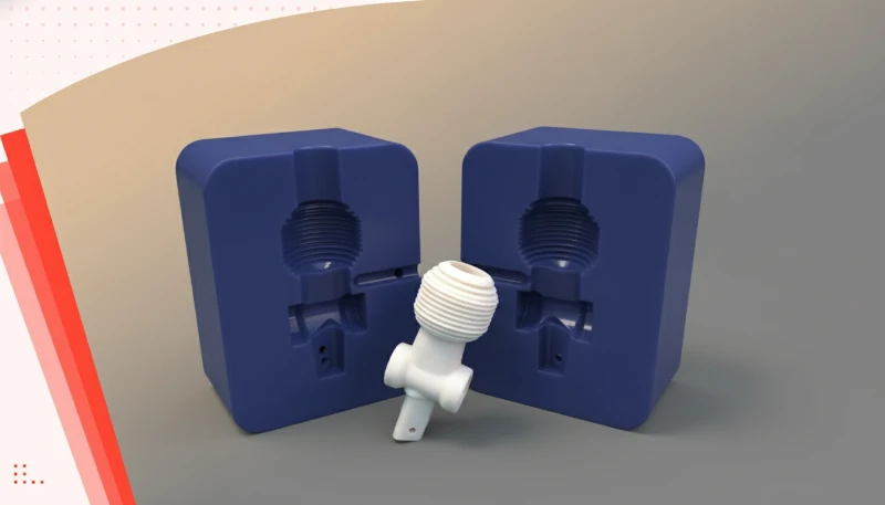
Um molde de injeção e a razão da sua importância são definidos pela função, pelas limitações e pelos compromissos explicados nesta secção. Um molde de injeção é uma ferramenta personalizada, maquinada em aço ou alumínio, que define a forma, o acabamento superficial e a exatidão dimensional de cada peça de plástico produzida pelo processo de moldagem por injeção. Em termos simples: o molde é um bloco metálico oco no qual é cortada uma cavidade. O plástico fundido é injetado sob alta pressão nessa cavidade, arrefece e solidifica, e o molde abre para libertar a peça acabada.
Porque é tão importante? Porque a qualidade começa no molde. Se as dimensões da cavidade tiverem um desvio de apenas 0.05 mm, cada peça apresentará esse erro ao longo de toda a série de produção — que pode atingir 100,000 peças ou mais. O molde também controla o acabamento da superfície (brilhante, mate, texturado), a localização das linhas de separação, das marcas dos pontos de injeção e das linhas de soldadura. Na nossa fábrica, vemos regularmente peças que «quase funcionam» porque o molde foi concebido sem ângulo de saída suficiente ou porque o ponto de injeção foi colocado numa zona de elevada tensão. São lições dispendiosas que um projeto adequado do molde evita desde o início.
Com mais de 20 anos de experiência e instalações internas de fabrico de moldes, a nossa equipa construiu milhares de moldes de produção — desde ferramentas simples de uma cavidade a moldes complexos de várias cavidades com elevadores, elementos deslizantes e sistemas de canais quentes.
Quais são os principais componentes de um molde de injeção?
Um molde de injeção para produção é muito mais do que duas metades de um bloco metálico. É um conjunto de precisão com 7 subsistemas distintos, cada um com uma função específica. Compreender estes componentes é essencial, quer esteja a analisar um orçamento de molde, quer a diagnosticar um problema de produção.
Sistema de alimentação (canal e ponto de injeção)
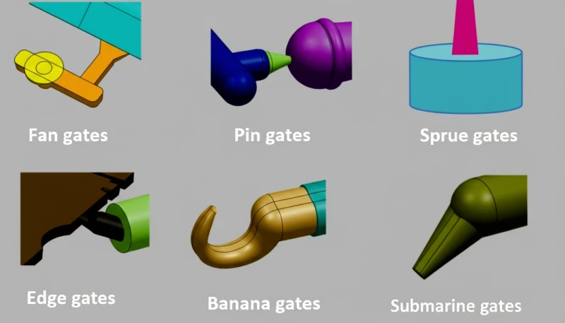
O sistema de alimentação é a rede de canais que conduz o plástico fundido do bico da máquina até à cavidade do molde. É constituído pelo canal de injeção (o canal vertical principal), pelos canais de distribuição (canais horizontais de distribuição) e pelo ponto de injeção (a abertura final estreita para a cavidade). A conceção do ponto de injeção é uma das decisões mais críticas na engenharia de moldes: o tipo de ponto (lateral, submarino, pontual, em leque, de diafragma) e a localização afetam diretamente o aspeto da peça, a precisão dimensional e o padrão de enchimento. Um ponto de injeção mal posicionado pode causar jato livre, bolsas de ar ou linhas de soldadura excessivas — defeitos que nenhum ajuste dos parâmetros de processamento consegue corrigir por completo.
Sistema de arrefecimento
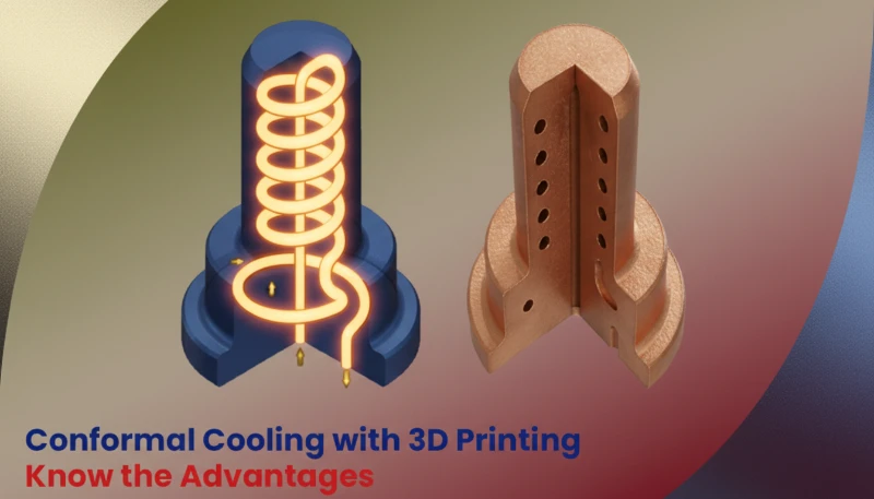
O sistema de refrigeração controla a temperatura do molde por meio de uma rede de canais de água perfurados nas placas. Uma refrigeração eficiente é o principal fator do tempo de ciclo, que determina diretamente o custo por peça. Um molde com canais de refrigeração conformais bem projetados, que acompanham o contorno da cavidade, pode reduzir o tempo de ciclo em 20–40% em comparação com canais retos convencionais. Na prática, a refrigeração precisa ser equilibrada: o resfriamento desigual causa contração diferencial, empenamento e marcas de afundamento. Nossa equipe de engenharia utiliza a simulação MOLDFLOW1 para otimizar a disposição dos canais antes de cortar qualquer aço.
Sistema de ejeção
Quando a peça tiver arrefecido o suficiente para conservar a forma, o molde abre e o sistema de ejeção empurra a peça para fora do lado do macho. Os métodos de ejeção mais comuns são pinos ejetores (pinos redondos que empurram superfícies não críticas), placas extratoras (para peças cilíndricas ou em forma de caixa) e ejeção por jato de ar (para peças de paredes finas). O sistema de ejeção deve ser concebido para que a peça não empene, não fique presa nem seja danificada durante a remoção. O posicionamento dos pinos ejetores é uma arte — coloque-os em superfícies não visíveis e assegure que a força de ejeção está equilibrada para evitar a deformação da peça.
Sistema de ventilação
Quando o plástico fundido enche a cavidade a velocidades de injeção que podem ultrapassar 100 mm/s, o ar que se encontrava no interior tem de ser evacuado. O sistema de ventilação possui canais estreitos (normalmente com 0.01–0.03 mm de profundidade) que deixam o ar escapar, mas são demasiado pequenos para permitir a passagem de plástico e a formação de rebarbas. Uma ventilação insuficiente provoca marcas de queimadura (efeito diesel — o ar aprisionado entra literalmente em ignição), enchimentos incompletos (as bolsas de ar impedem o enchimento total) e uma pressão interna elevada que pode danificar o molde. Segundo a nossa experiência, os problemas de ventilação representam cerca de 15–20% de todas as questões de qualidade relacionadas com o molde que encontramos durante a amostragem T1.
Sistema de posicionamento e alinhamento
O molde possui três níveis de precisão de posicionamento. As colunas-guia proporcionam o alinhamento grosseiro durante o fecho do molde. Os bloqueios cónicos (também designados bloqueios laterais) proporcionam o alinhamento intermédio das bases do molde. Por fim, os próprios insertos do macho e da cavidade são maquinados com tolerâncias extremamente apertadas para um alinhamento final preciso. Cada nível aperfeiçoa o posicionamento — se as colunas-guia estiverem gastas ou os bloqueios danificados, surgirão rebarbas, desvios dimensionais e desgaste acelerado da ferramenta.
Como são classificados os moldes de injeção?
Esta secção aborda a classificação dos moldes de injeção e o respetivo impacto no custo, na qualidade, nos prazos ou no risco de aprovisionamento. Os moldes de injeção são classificados segundo várias dimensões, e compreender estas classificações ajuda a especificar o molde adequado às suas necessidades de produção.
Por sistema de canais: moldes de câmara quente usam canais aquecidos para manter o plástico fundido, eliminando resíduos dos canais e reduzindo o tempo de ciclo — ideais para grandes volumes. Moldes de câmara fria são mais simples e baratos de fabricar, sendo adequados a volumes menores ou a materiais que se degradam em câmaras quentes.
Por número de cavidades: moldes de cavidade única produzem uma peça por ciclo. Moldes multicavidade produzem várias peças idênticas por ciclo; por exemplo, um molde de 4 cavidades fabrica 4 peças por injeção. Moldes família produzem peças diferentes no mesmo molde e ciclo — úteis para conjuntos, mas mais difíceis de balancear.
Por finalidade de produção: moldes de protótipo, às vezes chamados de ferramentas brandas, são fabricados em alumínio ou aço macio para séries curtas de 100–1.000 peças — são rápidos e baratos, mas têm vida útil limitada. Moldes de produção, ou ferramentas rígidas, são fabricados em aço endurecido para séries de 100.000 a milhões de peças.
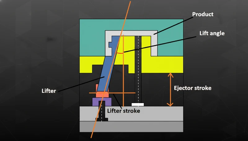
Por estrutura do molde: moldes de duas placas são os mais simples e comuns — dividem-se em duas metades na linha de partição. Moldes de três placas incluem uma placa extratora que separa automaticamente o canal das peças. Moldes com ações laterais incorporam gavetas ou levantadores para peças com rebaixos ou roscas externas.
O que envolve o processo de conceção de moldes de injeção?
É na conceção do molde que se decide o sucesso ou o fracasso do fabrico. Um molde bem concebido funciona de forma fiável durante centenas de milhares de ciclos. Um molde mal concebido causará problemas de qualidade, tempos de paragem e modificações dispendiosas ao longo de toda a sua vida útil. O processo de conceção segue uma sequência estruturada que os fabricantes de moldes experientes nunca omitem.
Etapa 1: análise da peça e revisão DFM
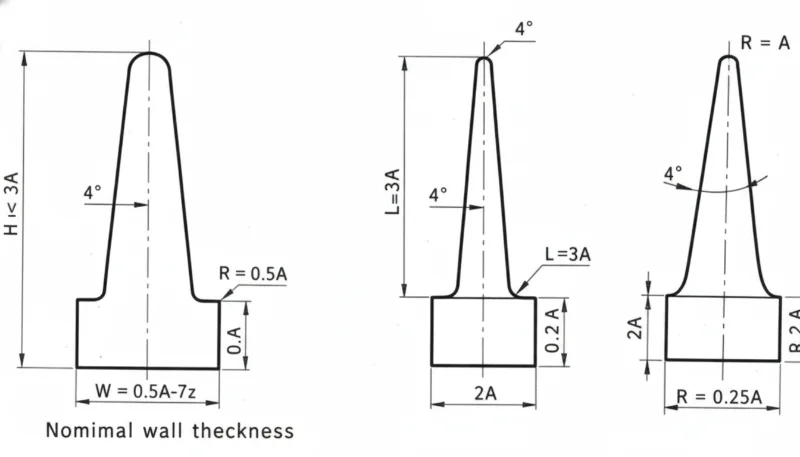
Antes de iniciar qualquer projeto de molde, a equipe de engenharia realiza uma análise completa de Projeto para Manufaturabilidade (DFM)2 da peça. Essa análise examina a uniformidade da espessura das paredes — idealmente 2–4 mm para a maioria dos plásticos de engenharia —, os ângulos de desmolde — mínimo de 0,5° por lado, com 1–2° recomendados —, as proporções das nervuras — cuja espessura não deve ultrapassar 60% da parede nominal para evitar marcas de afundamento — e os rebaixos que exigirão ações laterais. Em nossa experiência, cerca de 30% dos projetos de peças recebidos precisam de pelo menos pequenas alterações antes de poderem ser ferramentados com eficiência. Identificar esses problemas durante a DFM evita semanas de retrabalho posteriormente.
Passo 2: Simulação do fluxo no molde
Utilizando o MOLDFLOW ou software de simulação semelhante, a equipa de projeto prevê como o plástico fundido encherá a cavidade, onde se formarão as linhas de soldadura, como a peça contrairá e empenará e se a disposição do arrefecimento proporcionará uma distribuição uniforme da temperatura. A simulação não é opcional para moldes de produção — é a diferença entre um molde que funciona corretamente no primeiro ensaio e outro que necessita de três ciclos de modificações do aço. Os nossos 8 engenheiros seniores executam simulações em todos os moldes que fabricamos e utilizam os resultados para otimizar a localização dos pontos de injeção, a disposição dos canais de arrefecimento e os parâmetros de processamento antes de se retirar a primeira apara de aço.
Etapa 3: seleção do aço e disposição do molde
A seleção do aço depende do volume de produção previsto, do material plástico e dos requisitos de acabamento superficial. O P20 é o aço de referência para moldes — adequado a 100,000–500,000 ciclos com a maioria dos plásticos de engenharia. O H13 é um aço para trabalho a quente que suporta resinas de alta temperatura (PC, PEEK) e materiais abrasivos reforçados com fibra de vidro. O S136 é um aço inoxidável para ferramentas utilizado quando é necessária resistência à corrosão ou quando a peça exige um acabamento superficial polido a espelho SPI A-1. A configuração do molde determina a disposição das cavidades, o percurso dos canais, as posições dos canais de refrigeração e as dimensões globais da base do molde — e tudo isto tem de caber nas dimensões dos pratos da máquina de moldação por injeção pretendida.
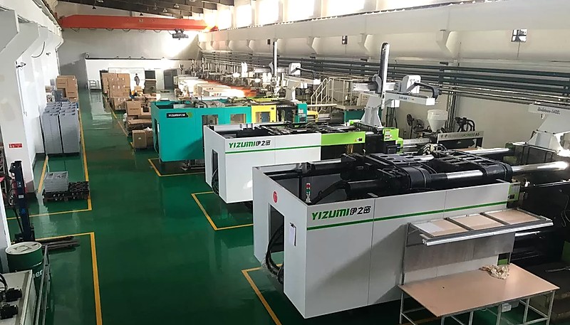
Os nossos 8 engenheiros seniores utilizam UG, SOLIDWORKS e MOLDFLOW para projetar moldes otimizados para as nossas 47 máquinas de moldação por injeção, assegurando que cada molde é concebido especificamente para o ambiente de produção exato onde irá funcionar.
Etapa 4: projeto detalhado e emissão do desenho 2D
A fase final de conceção produz um conjunto completo de desenhos 2D para todos os componentes do molde — insertos da cavidade, insertos do macho, corrediças, levantadores, pinos extratores, tampões de refrigeração e a própria base do molde. Cada componente recebe tolerâncias adequadas à sua função: as dimensões da cavidade são mantidas em ±0.01 mm ou menos para peças de precisão, enquanto os componentes estruturais têm tolerâncias mais amplas. O pacote de conceção completo é revisto e aprovado antes do início da maquinação.
"A simulação do fluxo do molde pode prever a localização das linhas de soldadura e o empeno da peça antes de cortar qualquer aço."True
As ferramentas modernas de simulação, como o MOLDFLOW, utilizam a análise por elementos finitos para modelar com elevada exatidão o fluxo, o arrefecimento e a contração dos polímeros. Prever linhas de soldadura, bolsas de ar e padrões de empeno durante a fase de projeto é uma prática normal nos fabricantes profissionais de moldes — e evita modificações dispendiosas do aço após a amostragem T1.
"Os moldes de alumínio podem produzir peças com a mesma qualidade dos moldes de aço endurecido em produção de grande volume."False
Os moldes de alumínio são excelentes para prototipagem e séries de baixo volume (menos de 10.000 peças), mas não têm a resistência ao desgaste nem a estabilidade térmica do aço temperado. Em séries de produção superiores a 50.000 peças, os moldes de aço (P20, H13, S136) mantêm muito melhor a precisão dimensional e o acabamento superficial ao longo do tempo.
Como é Fabricado um Molde de Injeção Passo a Passo?
Depois de finalizado e aprovado o projeto, o molde entra na fase de fabrico. É aqui que a maquinação de precisão transforma blocos de aço em bruto na ferramenta complexa que produzirá as suas peças. O prazo normal para um molde de produção é de 4–8 semanas, consoante a complexidade.
Fase 1: aquisição de material e desbaste
A base do molde e os blocos da cavidade e do núcleo são encomendados a fornecedores de aço. As bases de molde padrão (LKM, DME, HASCO) estão disponíveis de imediato, enquanto os insertos da cavidade são maquinados à medida a partir de blocos maciços de aço-ferramenta. O desbaste remove a maior parte do material com fresas de topo de grande diâmetro e elevadas taxas de remoção de material. Após o desbaste, o aço é submetido a alívio de tensões (tratamento térmico) para eliminar tensões internas que poderiam causar desvios dimensionais posteriores. Esta etapa é frequentemente omitida pelas empresas de moldes de baixo custo — e manifesta-se sempre como instabilidade dimensional após alguns milhares de ciclos.
Fase 2: Maquinagem CNC de precisão e EDM
Após o desbaste e o tratamento térmico, os insertos da cavidade e do núcleo recebem usinagem de acabamento em centros de fresamento CNC de alta velocidade capazes de manter precisão posicional de ±0,005 mm. Recursos inacessíveis às ferramentas de corte CNC — nervuras profundas, cantos internos vivos e superfícies 3D complexas — são usinados por Eletroerosão (EDM)3. A EDM por penetração cria formas complexas de cavidade 3D ao erodir o aço com faíscas elétricas controladas. A EDM a fio corta perfis e furos passantes precisos por meio de um eletrodo de fio fino. Ambos os processos são essenciais para moldes de produção.
Fase 3: acabamento superficial e polimento
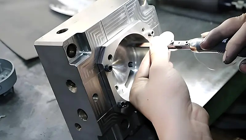
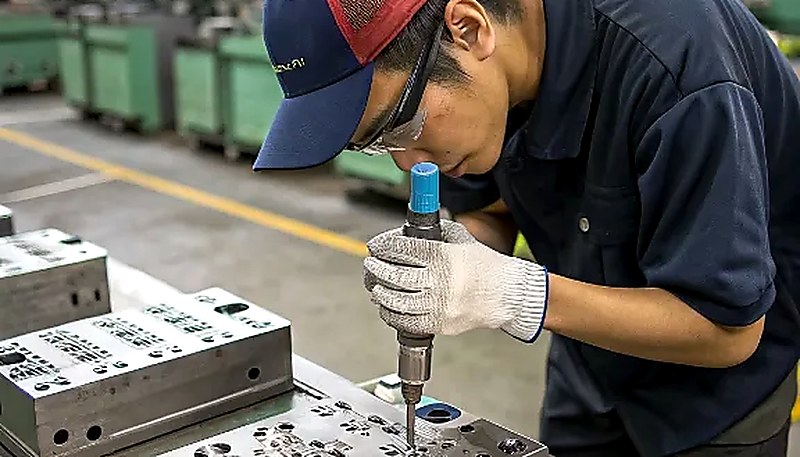
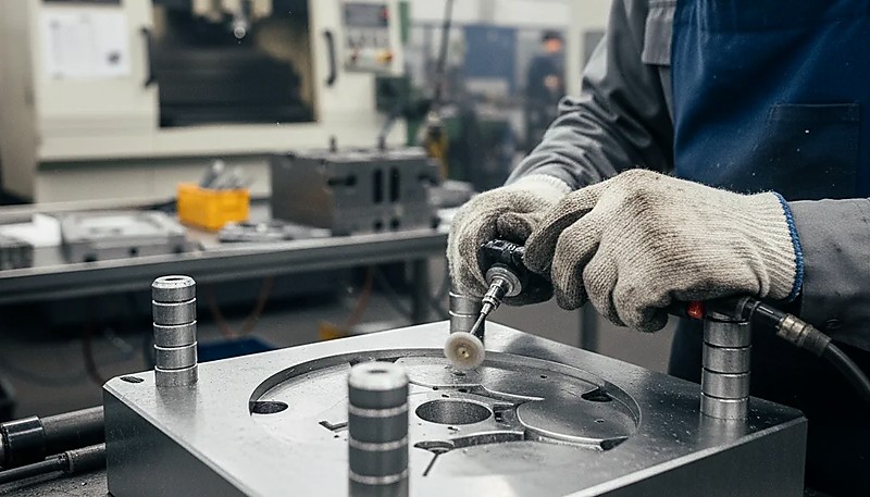
O acabamento da superfície da cavidade determina diretamente o acabamento superficial da peça. As normas de acabamento SPI variam entre A-1 (polimento espelhado, polimento com diamante #3) e D-3 (jateamento a seco, pedra de grão 240). Os moldes para lentes óticas podem exigir uma rugosidade superficial inferior a Ra 0.01 μm, enquanto as peças estruturais normalmente apenas necessitam de um acabamento SPI B-2 (papel de grão 320). O polimento é um trabalho manual realizado por profissionais qualificados — exige muito tempo e representa uma parte significativa do custo total do molde em aplicações que requerem um acabamento de elevada qualidade.
Fase 4: montagem, ensaios e amostragem T1
Todos os componentes maquinados são montados na base do molde. O sistema de refrigeração é submetido a um ensaio de pressão para detetar fugas. Os pinos-guia, as corrediças, os extratores inclinados e os pinos extratores são montados e verificados quanto à suavidade do funcionamento. Em seguida, o molde é instalado na máquina de moldação por injeção para a amostragem T1 (primeira peça). A amostragem T1 é um marco crítico — é a primeira vez que o plástico fundido enche o molde de produção real. As amostras são medidas com base no desenho da peça e todos os desvios dimensionais são registados para ajustar o molde.
A nossa unidade interna de moldes produz mais de 100 conjuntos por mês e dispõe de capacidades completas de inspeção CNC, EDM e CMM — o que significa que controlamos todo o processo de fabrico do molde, desde a conceção até à amostragem T1, sem depender de fornecedores externos.
"O tempo de refrigeração do molde representa normalmente 50–70% do tempo total do ciclo de moldação por injeção."True
Na maioria das aplicações de moldagem por injeção, a fase de arrefecimento domina o ciclo. Otimizar o projeto dos canais de refrigeração — através de refrigeração conformada, sistemas de defletores ou comutação entre água quente e fria — é a forma mais eficaz de reduzir o tempo de ciclo e o custo por peça sem comprometer a qualidade.
"Um molde que produza peças de qualidade durante a amostragem T1 nunca precisará de modificações."False
As amostras T1 são produzidas em condições laboratoriais cuidadosamente controladas. À medida que os volumes de produção aumentam, as variações entre lotes de material, o desgaste da máquina, a temperatura ambiente e a técnica do operador podem revelar problemas que não eram evidentes durante a amostragem inicial. A maioria dos moldes de produção passa por 1–3 rondas de afinação após T1 para otimizar as condições reais de produção.
Porque é que a qualidade do molde determina a qualidade da peça final?
Esta secção explica como a qualidade do molde determina a qualidade final da peça e o seu impacto no custo, na qualidade, nos prazos ou no risco de abastecimento. Há um ditado na indústria da moldagem por injeção: “O molde é a qualidade.” Os parâmetros de processamento (temperatura, pressão, velocidade e tempo) podem ser ajustados dentro de um intervalo, mas não conseguem compensar problemas fundamentais no projeto do molde. Se o ponto de injeção estiver no local errado, nenhum ajuste da pressão eliminará a linha de soldadura resultante. Se o arrefecimento for irregular, nenhum tempo de compactação impedirá o empeno. Se os pinos extratores forem insuficientes ou estiverem mal posicionados, as peças deformar-se-ão durante a extração, por mais cuidadosa que seja a afinação da máquina.
A qualidade do molde afeta cinco aspectos críticos do resultado da produção. Precisão dimensional: a cavidade deve ser usinada para compensar a contração do plástico, normalmente de 0,5–2,5% conforme o material e a geometria da peça, e o molde deve manter essas dimensões por centenas de milhares de ciclos sem desgaste. Acabamento superficial: o polimento do aço da cavidade determina o acabamento da peça — nenhum processo secundário o melhora. Consistência: um molde de precisão mantém a variação entre peças abaixo de 0,05 mm; um molde mal construído pode desviar 0,2 mm ou mais à medida que se desgasta. Tempo de ciclo: um projeto de refrigeração eficiente economiza segundos em cada ciclo — e, em 500.000 peças, economizar 2 segundos por ciclo significa 278 horas a menos de máquina.
Vida útil do molde: um molde de produção corretamente endurecido e mantido pode operar por 500.000 a mais de 1.000.000 de ciclos antes de exigir uma reforma significativa.
Como escolher o fabricante de moldes de injeção certo?
Esta secção aborda a escolha do fabricante de moldes de injeção adequado e o respetivo impacto no custo, na qualidade, nos prazos ou no risco de aprovisionamento. Escolher um fornecedor de moldes é uma decisão de longo prazo — trabalhará com esta empresa durante toda a vida de produção do seu produto, que pode prolongar-se por anos. Eis os fatores que realmente importam, com base na nossa experiência de trabalho com centenas de clientes.
Capacidade interna de ferramentaria: uma empresa que projeta, usina, monta e testa moldes sob o mesmo teto sempre entregará resultados melhores que outra que terceiriza etapas individuais. Quando projetista, ferramenteiro e engenheiro de processos trabalham no mesmo prédio, os problemas são resolvidos em horas, não em semanas. Pergunte se a ferramentaria possui centros CNC, máquinas de EDM e equipamentos de inspeção CMM próprios ou se subcontrata essas operações.
Profundidade de engenharia: as melhores ferramentarias não apenas executam seu projeto — elas o aprimoram. Uma equipe de engenharia sólida identificará problemas de DFM que passaram despercebidos, sugerirá sistemas de alimentação melhores e otimizará a refrigeração para sua geometria específica. Pergunte sobre seus recursos de simulação — MOLDFLOW é o padrão do setor — e sobre a experiência dos engenheiros de projeto.
Conhecimento de materiais: diferentes plásticos se comportam de maneiras muito distintas no molde. Uma ferramentaria com experiência em mais de 400 materiais sabe como cada resina flui, contrai e se degrada — e projeta os moldes de acordo. Se a peça usa náilon reforçado com fibra de vidro, por exemplo, o molde precisa de aço endurecido, no mínimo H13, nas áreas de desgaste, pois as fibras de vidro são extremamente abrasivas para ferramentas P20 convencionais.
Comunicação e suporte: para compradores internacionais, uma comunicação clara em inglês não é luxo — é necessidade. Um único mal-entendido sobre uma tolerância dimensional pode resultar em um molde que produz peças incompatíveis com o conjunto. Procure fornecedores com gerentes de projeto dedicados que falem inglês e engenheiros capazes de compreender seus requisitos técnicos sem ciclos constantes de esclarecimento.
Se você está avaliando fornecedores de moldes para seu próximo projeto, nossa equipe da ZetarMold pode fornecer uma proposta detalhada de projeto de molde e um orçamento competitivo — incluindo feedback de DFM, análise de fluxo do molde e um cronograma claro desde a aprovação do projeto até a amostragem T1. Consulte nosso guia de seleção de fornecedores de moldagem por injeção para obter uma estrutura completa de avaliação e escolha de parceiros de fabricação.
Com experiência em mais de 400 materiais plásticos e certificação segundo as normas ISO 9001, ISO 13485, ISO 14001 e ISO 45001, a nossa equipa de engenharia fornece recomendações de projeto de moldes específicas para cada material e sustentadas por dados de produção reais.
Perguntas mais frequentes
Quanto tempo demora a fabricar um molde de injeção?
Um molde de produção padrão de cavidade única demora normalmente 4–6 semanas desde a aprovação do desenho até à amostragem T1. Os moldes complexos de múltiplas cavidades com corrediças, extratores inclinados ou sistemas de canais quentes podem demorar 8–12 semanas, consoante o número de ações laterais e os requisitos de acabamento superficial. Os moldes de protótipo fabricados em alumínio podem ficar concluídos em apenas 1–3 semanas. Os principais fatores que determinam o prazo são a complexidade da peça (contrassaídas, paredes finas, tolerâncias apertadas), o número de cavidades e a utilização, ou não, de um sistema de canais quentes.
Qual é o custo típico de um molde de injeção?
Sim — um molde família pode produzir várias peças diferentes no mesmo ciclo de moldação por injeção, o que é especialmente útil em conjuntos de produto que exigem vários componentes em quantidades correspondentes. Contudo, estes moldes exigem um equilíbrio rigoroso do fluxo para garantir o enchimento completo e consistente de cada cavidade em todos os ciclos. Funcionam melhor quando as peças têm volume, espessura de parede e requisitos de material semelhantes. Para geometrias ou dimensões muito diferentes, moldes dedicados separados podem evitar compromissos de qualidade.
Um molde de injeção pode produzir várias peças diferentes?
Um molde de canais quentes utiliza canais aquecidos para manter o plástico fundido no sistema de alimentação, eliminando totalmente os resíduos dos canais e reduzindo frequentemente o tempo de ciclo em 1–3 segundos por injeção. Em contrapartida, os sistemas de canais quentes aumentam em 30–50% o custo inicial de construção do molde e exigem manutenção adicional comparativamente aos canais frios. Um molde de canais frios utiliza canais não aquecidos, nos quais o material solidifica juntamente com as peças e tem de ser separado e novamente triturado. Os canais frios são mais simples, mais económicos e preferíveis para séries de produção de menor volume ou aplicações de prototipagem.
Qual é a diferença entre um molde de canal quente e um molde de canal frio?
Um molde de canal quente utiliza canais aquecidos para manter o plástico fundido no interior do sistema de canais, eliminando totalmente os resíduos dos canais e reduzindo frequentemente o tempo de ciclo em 1–3 segundos por injeção. Em contrapartida, os sistemas de canal quente acrescentam 30–50% ao custo inicial do molde e exigem mais manutenção. Um molde de canal frio utiliza canais não aquecidos, nos quais o canal solidifica juntamente com as peças e tem de ser separado e novamente granulado. Os canais frios são mais simples, mais baratos e preferíveis para produções de menor volume ou protótipos.
Quantas peças pode um molde de injeção produzir antes de se desgastar?
A moldagem por injeção padrão atinge consistentemente tolerâncias de mais ou menos 0,05 a 0,10 mm para dimensões inferiores a 25 mm com moldes devidamente projetados e condições de processamento estáveis. A moldagem de precisão com design de entrada otimizado, arrefecimento controlado e monitorização apertada do processo pode atingir mais ou menos 0,025 mm para características dimensionais críticas em peças bem projetadas. As tolerâncias para dimensões maiores escalam aproximadamente proporcionalmente — tipicamente mais ou menos 0,1 a 0,3 mm para dimensões superiores a 100 mm. O molde deve ser projetado com compensação de contração específica do material apropriada para atingir de forma fiável estes alvos de tolerância consistentemente ao longo de toda a produção.
Que tolerâncias pode a moldagem por injeção alcançar?
A simulação de fluxo do molde prevê exatamente como o plástico fundido preencherá a cavidade, onde as linhas de solda se formarão e como a peça irá contrair e empenar — tudo antes de qualquer corte no aço. Isto elimina a dispendiosa abordagem de tentativa e erro de construir um molde e depois modificá-lo após os primeiros testes (T1) revelarem problemas. As modificações no aço normalmente acrescentam 2–4 semanas e $2.000–$10.000+ por ronda de modificação. Oficinas de moldes profissionais executam simulação em cada molde de produção como um passo padrão de design porque o custo de uma simulação é uma fração minúscula do custo de uma única modificação no aço.
Por que é importante a simulação de fluxo do molde antes de construir um molde?
A simulação de fluxo do molde prevê exatamente como o plástico fundido preencherá a cavidade, onde as linhas de solda se formarão e como a peça irá contrair e empenar — tudo antes de qualquer corte no aço. Isto elimina a dispendiosa abordagem de tentativa e erro de construir um molde e depois modificá-lo após os primeiros testes (T1) revelarem problemas. As modificações no aço normalmente acrescentam 2–4 semanas e $2.000–$10.000+ por ronda. Oficinas de moldes profissionais executam simulação em cada molde de produção como um passo padrão porque o custo de uma execução de simulação é uma fração do custo de uma modificação no aço.
Que manutenção necessita um molde de injeção?
Os moldes de produção requerem manutenção programada em intervalos regulares para manter a qualidade da peça e prolongar a vida útil da ferramenta. As principais tarefas de manutenção incluem limpeza e polimento da cavidade a cada 50.000–100.000 ciclos para restaurar o acabamento superficial, inspeção e lubrificação dos pinos ejetores, desincrustação dos canais de arrefecimento para manter o desempenho térmico, inspeção da área da entrada para danos por erosão (especialmente importante com materiais preenchidos com vidro) e inspeção dos mecanismos de corrediças e levantadores para desgaste. Um programa disciplinado de manutenção preventiva normalmente estende a vida útil do molde em 2–3 vezes e evita dispendiosas paragens de produção não planeadas.
Simulação MOLDFLOW: Moldflow é um software de simulação de moldagem por injeção de plástico desenvolvido pela Autodesk que utiliza análise de elementos finitos para prever o fluxo do polímero, a refrigeração e a contração durante o processo de injeção. ↩
Projeto para Manufaturabilidade (DFM): é a prática de projetar peças para que sejam fabricadas de forma fácil e econômica, considerando fatores como uniformidade da espessura das paredes, ângulos de desmolde, proporções das nervuras e minimização de rebaixos, a fim de garantir uma moldagem por injeção bem-sucedida. ↩
Eletroerosão (EDM): é um processo de usinagem de precisão que remove material por meio de faíscas elétricas controladas entre um eletrodo e a peça, sendo capaz de produzir geometrias complexas em aço endurecido que não podem ser obtidas com ferramentas de corte convencionais. ↩