Bir enjeksiyon kalıbı, plastik imalatındaki en pahalı ve en kritik araçtır. Doğru yapılırsa inçin binde biriyle ölçülen toleranslarda milyonlarca özdeş parça üretebilirsiniz. Yanlış yapılırsa makineden çıkan her parça hurdaya dönüşür. Şanghay fabrikamızda 20 yılı aşkın süredir enjeksiyon kalıplama takımları üretiyoruz; bu süre boyunca karşılaşılabilecek hemen her kalıp imalat hatasını gördük. Bu kılavuz, öğrendiklerimizi doğrudan kullanabileceğiniz, mühendisten mühendise pratik önerilere dönüştürüyor.
- Enjeksiyon kalıbı, erimiş plastiğe tekrarlanabilir, üretim kalitesinde parça şekli veren hassas bir takımdır
- Kalıp tasarımı 7 temel alt sistem içerir: yolluk, soğutma, çıkarma, hava tahliyesi, konumlandırma, kalıp gözü ve çerçeve
- Çelik seçimi (P20, H13, S136), kalıp ömrünü ve parça yüzey kalitesini doğrudan belirler
- Tipik bir üretim kalıbının imalatı 4–8 hafta sürer ve karmaşıklığa bağlı olarak $10,000–$100,000 üzeri tutar
- Şirket içi bir kalıp atölyesiyle çalışmak, dış kaynak kullanımına kıyasla teslim süresini %30–50 azaltır
Enjeksiyon Kalıbı Nedir ve Neden Önemlidir?
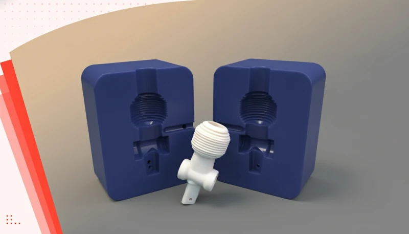
Bir enjeksiyon kalıbının ne olduğu ve neden önemli olduğu, bu bölümde açıklanan işlev, kısıtlar ve ödünleşimlerle tanımlanır. Enjeksiyon kalıbı, enjeksiyon kalıplama prosesiyle üretilen her plastik parçanın şeklini, yüzey kalitesini ve boyutsal doğruluğunu belirleyen, özel işlenmiş çelik veya alüminyum bir takımdır. Basitçe ifade etmek gerekirse kalıp, içine bir kalıp gözü açılmış içi boş bir metal bloktur. Erimiş plastik yüksek basınç altında bu göze enjekte edilir, soğur, katılaşır ve kalıp bitmiş parçayı çıkarmak için açılır.
Bu neden bu kadar önemlidir? Çünkü kalite kalıpta başlar. Kavite ölçüleri yalnızca 0.05 mm saparsa üretim serisinin tamamındaki her parça bu hatayı taşır; bu da 100,000 veya daha fazla parça anlamına gelebilir. Kalıp ayrıca yüzey finisajını (parlak, mat, dokulu), ayırma çizgilerinin, yolluk izlerinin ve kaynak çizgilerinin konumunu belirler. Fabrikamızda, kalıp yeterli çıkma açısı olmadan tasarlandığı veya yolluk yüksek gerilimli bir alana yerleştirildiği için “neredeyse çalışan” parçalarla sıkça karşılaşıyoruz. Doğru kalıp tasarımı bu pahalı dersleri en baştan önler.
20 yılı aşkın deneyim ve şirket içi kalıp imalat tesisimizle ekibimiz, basit tek gözlü kalıplardan eğik iticiler, sürgüler ve sıcak yolluk sistemlerine sahip karmaşık çok gözlü kalıplara kadar binlerce üretim kalıbı yapmıştır.
Bir Enjeksiyon Kalıbının Temel Bileşenleri Nelerdir?
Üretim sınıfı bir enjeksiyon kalıbı, bir metal bloğun iki yarısından çok daha fazlasıdır. Her biri belirli bir göreve sahip 7 ayrı alt sistemden oluşan hassas bir montajdır. Bir kalıp teklifini incelerken de üretim sorununu giderirken de bu bileşenleri anlamak şarttır.
Yolluk Sistemi (Yolluk ve Giriş)
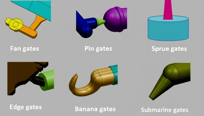
Yolluk sistemi, erimiş plastiği makine memesinden kalıp boşluğuna taşıyan kanal ağıdır. Sistem; ana dikey kanal olan yolluk burcundan, yatay dağıtım kanallarından ve boşluğa açılan son dar açıklık olan giriş yolluğundan oluşur. Yolluk tasarımı, kalıp mühendisliğindeki en kritik kararlardan biridir: yolluk türü (kenar, denizaltı, nokta, fan, diyafram) ve konumu; parça görünümünü, boyutsal doğruluğu ve dolum desenini doğrudan etkiler. Kötü konumlandırılmış bir yolluk; jet oluşumuna, hava ceplerine veya aşırı kaynak çizgilerine yol açabilir. Bunlar, proses parametrelerinin hiçbir şekilde ayarlanmasıyla tamamen giderilemeyecek kusurlardır.
Soğutma Sistemi
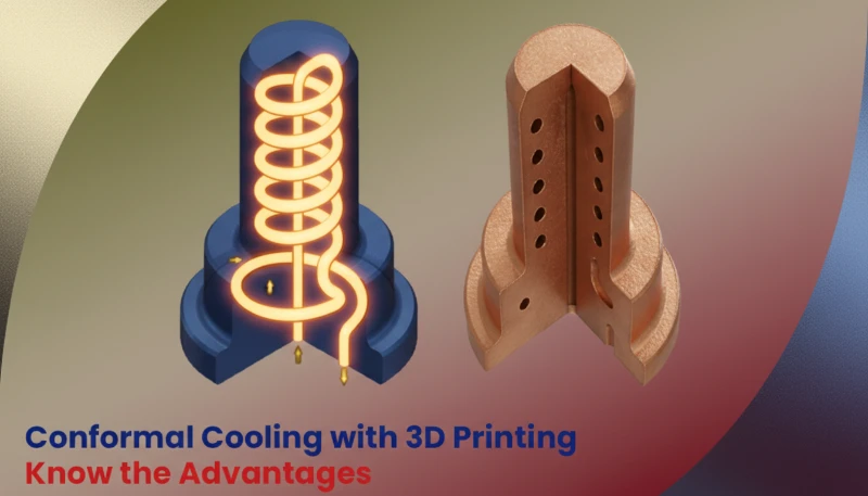
Soğutma sistemi, kalıp plakalarına açılan su kanalları ağıyla kalıp sıcaklığını kontrol eder. Verimli soğutma, parça başı maliyeti doğrudan belirleyen çevrim süresindeki en önemli etkendir. İyi tasarlanmış konformal soğutma kanallarına sahip bir kalıp, geleneksel düz delikli kanallara kıyasla çevrim süresini %20–40 azaltabilir. Uygulamada soğutma dengeli olmalıdır: eşit olmayan soğutma farklı oranlarda çekmeye, çarpılmaya ve çökme izlerine yol açar. Mühendislik ekibimiz, çelik kesilmeden önce soğutma düzenini optimize etmek için MOLDFLOW simülasyonu1 kullanır.
Fırlatma Sistemi
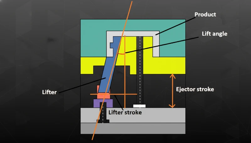
Parça şeklini koruyacak kadar soğuduğunda kalıp açılır ve çıkarma sistemi parçayı maça tarafından iter. En yaygın çıkarma yöntemleri; itici pimler (kritik olmayan yüzeylere basan yuvarlak pimler), sıyırıcı plakalar (silindirik veya kutu biçimli parçalar için) ve hava üflemeli çıkarmadır (ince duvarlı parçalar için). Çıkarma sistemi, parçanın çıkarma sırasında çarpılmaması, yapışmaması veya hasar görmemesi için tasarlanmalıdır. İtici pim yerleşimi ustalık gerektirir: pimleri görünmeyen yüzeylere koyun ve parça deformasyonunu önlemek için çıkarma kuvvetinin dengeli olmasını sağlayın.
Havalandırma Sistemi
Erimiş plastik, 100 mm/s değerini aşabilen enjeksiyon hızlarında gözü doldururken gözün içindeki havanın bir yere çıkması gerekir. Havalandırma sistemi, havanın kaçmasına izin veren ancak plastiğin çapak yaparak geçemeyeceği kadar küçük olan dar kanallar (genellikle 0.01–0.03 mm derinliğinde) sağlar. Yetersiz havalandırma; yanık izlerine (dizel etkisi — hapsolmuş hava kelimenin tam anlamıyla tutuşur), eksik baskılara (hava cepleri tam dolumu engeller) ve kalıba zarar verebilecek yüksek iç basınca neden olur. Deneyimlerimize göre havalandırma sorunları, T1 numune alma sırasında karşılaştığımız kalıpla ilgili tüm kalite sorunlarının yaklaşık %15–20’sini oluşturur.
Konumlandırma ve Hizalama Sistemi
Kalıpta üç konumlandırma hassasiyeti seviyesi vardır. Kılavuz kolonlar kalıp kapanırken kaba hizalama sağlar. Konik kilitler (yan kilitler de denir) kalıp plakalarının ara hassasiyette hizalanmasını sağlar. Son olarak, maça ve kavite insertleri nihai ve hassas hizalama için son derece dar toleranslarla işlenir. Her seviye konumlandırmayı daha da hassaslaştırır — kılavuz kolonlar aşınmışsa veya kilitler hasarlıysa çapak, boyutsal kaymalar ve hızlanan takım aşınması görülür.
Enjeksiyon kalıpları nasıl sınıflandırılır?
Bu bölüm, enjeksiyon kalıplarının sınıflandırılması ve bunun maliyet, kalite, zamanlama veya tedarik riski üzerindeki etkisi hakkındadır. Enjeksiyon kalıpları çeşitli boyutlara göre kategorize edilir ve bu sınıflandırmaları anlamak, üretim ihtiyaçlarınız için doğru aracı belirlemenize yardımcı olur.
Yolluk sistemine göre: Sıcak yolluklu kalıplar, plastiği yolluk içinde eriyik halde tutmak için ısıtılmış kanallar kullanır; böylece yolluk atığını ortadan kaldırır ve çevrim süresini kısaltır. Bu kalıplar yüksek hacimli üretim için idealdir. Soğuk yolluklu kalıpların üretimi daha basit ve ucuzdur; düşük hacimler veya sıcak yollukta bozunan malzemeler için uygundur.
Kavite sayısına göre: Tek kaviteli kalıplar her çevrimde bir parça üretir. Çok kaviteli kalıplar her çevrimde birden fazla özdeş parça üretir; örneğin 4 kaviteli bir kalıp her atımda 4 parça çıkarır. Aile kalıpları aynı çevrimde farklı parçalar üretir; montajlar için kullanışlıdır ancak dengelenmeleri daha zordur.
Üretim amacına göre: Bazen yumuşak takım olarak da adlandırılan prototip kalıplar, 100–1.000 parçalık kısa seriler için alüminyumdan veya yumuşak çelikten yapılır; hızlı ve ucuzdur ancak ömürleri sınırlıdır. Üretim kalıpları, yani sert takımlar, 100.000 parçadan milyonlarca parçaya uzanan seriler için sertleştirilmiş çelikten yapılır.
Kalıp yapısına göre: İki plakalı kalıplar en basit ve en yaygın türdür; kalıp, ayırma çizgisinde iki yarıya ayrılır. Üç plakalı kalıplara, yolluğu parçalardan otomatik olarak ayıran bir sıyırıcı plaka eklenir. Yandan hareketli kalıplarda, ters açıya veya dış dişe sahip parçalar için kızaklar ya da eğik iticiler bulunur.
Enjeksiyon Kalıbı Tasarım Süreci Neleri İçerir?
Üretim başarısı veya başarısızlığı kalıp tasarımında belirlenir. İyi tasarlanmış kalıp yüz binlerce çevrim boyunca güvenilir biçimde çalışır. Kötü tasarlanmış kalıp, ömrü boyunca kalite sorunları, duruşlar ve pahalı değişikliklerle sizi uğraştırır. Tasarım prosesi, deneyimli kalıp ustalarının asla atlamadığı yapılandırılmış bir sıra izler.
Adım 1: Parça Analizi ve DFM İncelemesi
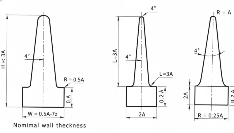
Herhangi bir kalıp tasarımına başlamadan önce mühendislik ekibi, parça üzerinde kapsamlı bir Üretilebilirlik için Tasarım (DFM)2 incelemesi yapar. Bu analiz; duvar kalınlığının eşitliğini (çoğu mühendislik plastiği için ideal değer 2–4 mm), kalıp çıkış açılarını (her yüz için en az 0,5°, önerilen 1–2°), nervür oranlarını (çökme izlerini önlemek için nervür kalınlığı nominal duvarın %60’ını geçmemelidir) ve yandan hareket gerektirecek ters açıları inceler. Deneyimlerimize göre aldığımız parça tasarımlarının yaklaşık %30’u verimli biçimde kalıplanmadan önce en azından küçük değişikliklere ihtiyaç duyuyor. Bu sorunları DFM aşamasında yakalamak, ileride haftalar sürecek yeniden çalışmaları önler.
Adım 2: Kalıp Akış Simülasyonu
Tasarım ekibi MOLDFLOW veya benzer bir simülasyon yazılımı kullanarak erimiş plastiğin kaviteyi nasıl dolduracağını, kaynak çizgilerinin nerede oluşacağını, parçanın nasıl çekilip çarpılacağını ve soğutma düzeninin eşit sıcaklık dağılımı sağlayıp sağlamayacağını öngörür. Üretim kalıplarında simülasyon isteğe bağlı değildir; ilk denemede doğru çalışan kalıpla üç tur çelik değişikliği gerektiren kalıp arasındaki farktır. Sekiz kıdemli mühendisimiz imal ettiğimiz her kalıpta simülasyon çalıştırır ve ilk çelik talaşı kaldırılmadan önce sonuçları giriş yerleşimini, soğutma kanalı düzenini ve işleme parametrelerini optimize etmek için kullanır.
Adım 3: Çelik Seçimi ve Kalıp Yerleşimi
Çelik seçimi beklenen üretim hacmine, plastik malzemeye ve yüzey kalitesi gereksinimlerine bağlıdır. P20 temel kalıp çeliğidir — çoğu mühendislik plastiğiyle 100,000–500,000 çevrim için uygundur. H13, yüksek sıcaklık reçinelerini (PC, PEEK) ve aşındırıcı cam elyaf dolgulu malzemeleri işleyebilen bir sıcak iş çeliğidir. S136, korozyon direnci gerektiğinde veya parça ayna polisajlı SPI A-1 yüzey kalitesi gerektirdiğinde kullanılan paslanmaz takım çeliğidir. Kalıp düzeni; kavite yerleşimini, yolluk güzergâhını, soğutma kanalı konumlarını ve genel kalıp tabanı boyutunu belirler — bunların tümü hedef enjeksiyon kalıplama makinesinin tabla ölçülerine sığmalıdır.
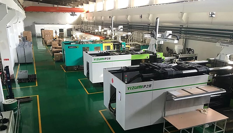
Sekiz kıdemli mühendisimiz, 47 enjeksiyon kalıplama makinemize göre optimize edilmiş kalıplar tasarlamak için UG, SOLIDWORKS ve MOLDFLOW kullanır; böylece her kalıp çalışacağı gerçek üretim ortamına özel olarak üretilir.
Adım 4: Ayrıntılı Tasarım ve 2D Teknik Resimlerin Yayımlanması
Son tasarım aşamasında her kalıp bileşeni için eksiksiz 2D teknik resim seti hazırlanır: kavite insertleri, maça insertleri, sürgüler, eğik iticiler, itici pimler, soğutma tapaları ve kalıp tabanının kendisi. Her bileşene işlevine göre tolerans verilir: hassas parçalarda kavite boyutları ±0.01 mm veya daha dar tutulurken yapısal bileşenlerin toleransları daha geniştir. Eksiksiz tasarım paketi işleme başlamadan önce incelenip onaylanır.
"Kalıp akış simülasyonu, herhangi bir çelik kesilmeden önce birleşme çizgisinin konumunu ve parçadaki çarpılmayı öngörebilir."True
MOLDFLOW gibi modern simülasyon araçları; polimer akışını, soğumayı ve çekmeyi yüksek doğrulukla modellemek için sonlu elemanlar analizini kullanır. Tasarım aşamasında birleşme çizgilerini, hava kapanlarını ve çarpılma biçimlerini öngörmek, profesyonel kalıphanelerde standart uygulamadır — ve T1 numune alımından sonra maliyetli çelik değişikliklerini önler.
"Alüminyum kalıplar, yüksek hacimli üretimde sertleştirilmiş çelik kalıplarla aynı parça kalitesini sağlayabilir."False
Sıcak kanallı kalıp, plastiği kanal sistemi içinde erimiş halde tutmak için ısıtılmış kanallar kullanır, böylece kanal atığını tamamen ortadan kaldırır ve genellikle her enjeksiyonda döngü süresini 1-3 saniye azaltır. Karşılığında, sıcak kanal sistemleri başlangıç kalıp maliyetine 30-50% ekler ve daha fazla bakım gerektirir. Soğuk kanallı kalıp, kanalların parçalarla birlikte katılaştığı ve ayrılıp yeniden öğütülmesi gereken ısıtılmamış kanallar kullanır. Soğuk kanallar daha basit, daha ucuzdur ve düşük hacimli üretim veya prototipleme için tercih edilir.
Enjeksiyon Kalıbı Adım Adım Nasıl Üretilir?
Tasarım tamamlanıp onaylandıktan sonra kalıp üretim aşamasına geçer. Bu aşamada hassas işleme, ham çelik blokları parçalarınızı üretecek karmaşık takıma dönüştürür. Bir üretim kalıbının tipik süresi, karmaşıklığa bağlı olarak 4–8 haftadır.
Aşama 1: Malzeme Tedariki ve Kaba İşleme
Kalıp tabanı ve kavite/maça blokları çelik tedarikçilerinden sipariş edilir. Standart kalıp tabanları (LKM, DME, HASCO) rafta hazır bulunurken kavite insertleri masif takım çeliği bloklarından özel olarak işlenir. Kaba işleme, yüksek malzeme kaldırma hızlarında büyük çaplı parmak frezeler kullanarak malzemenin büyük bölümünü kaldırır. Kaba işlemeden sonra çelik, ileride boyutsal sapmaya neden olabilecek iç gerilimleri gidermek için gerilim giderme işlemine (ısıl işlem) tabi tutulur. Bu adım düşük maliyetli kalıp atölyeleri tarafından sıklıkla atlanır ve birkaç bin çevrimden sonra her zaman boyutsal kararsızlık olarak ortaya çıkar.
Aşama 2: Hassas CNC İşleme ve EDM
Kaba işleme ve ısıl işlemin ardından kavite ve çekirdek insertleri, ±0,005 mm konum hassasiyetini koruyabilen yüksek hızlı CNC freze merkezlerinde son ölçülerine işlenir. CNC kesici takımlarının erişemediği derin nervürler, keskin iç köşeler ve karmaşık 3D yüzeyler, Elektro Erozyonla İşleme (EDM)3 yöntemiyle işlenir. Dalma erozyon, kontrollü elektrik kıvılcımlarıyla biçimi çeliğe aşındırarak karmaşık 3D kavite şekilleri oluşturur. Tel erozyon ise ince bir tel elektrotla hassas boydan boya delikler ve profiller keser. Her iki süreç de üretim kalıpları için vazgeçilmezdir.
Aşama 3: Yüzey Bitirme ve Parlatma
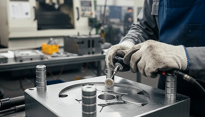
Boşluk yüzeyinin kalitesi doğrudan parçanın yüzeyinin kalitesini belirler. SPI bitirme standartları A-1’den (ayna cilası, #3 elmas cilası) D-3’e (kuru kumlama, 240 kumlu taş) kadar değişir. Optik mercek kalıpları Ra 0,01 μm’nin altında yüzey pürüzlülüğü gerektirebilirken yapısal parçalar genellikle yalnızca SPI B-2 (320 kumlu kağıt) kaplamaya ihtiyaç duyar. Parlatma, vasıflı ustalar tarafından yapılan manuel bir iştir; zaman alıcıdır ve yüksek kaliteli uygulamalar için toplam kalıp maliyetinin önemli bir bölümünü temsil eder.
Aşama 4: Montaj, Test ve T1 Numune Alma
İşlenmiş tüm bileşenler kalıp tabanına monte edilir. Soğutma sistemine sızıntı için basınç testi uygulanır. Kılavuz pimler, sürgüler, eğik iticiler ve itici pimler takılır ve sorunsuz çalıştıkları kontrol edilir. Ardından kalıp, T1 (ilk parça) numunesi için enjeksiyon kalıplama makinesine bağlanır. T1 numune alımı kritik bir kilometre taşıdır — erimiş plastiğin gerçek üretim kalıbını ilk kez doldurduğu aşamadır. Numuneler parça çizimine göre ölçülür ve boyutsal sapmalar kalıp ayarı için kaydedilir.
Şirket içi kalıp atölyemiz tam CNC, EDM ve CMM muayene kabiliyetleriyle ayda 100+ kalıp seti üretir — bu, dış tedarikçilere bağımlı olmadan tasarımdan T1 numune alımına kadar tüm kalıp üretim sürecini kontrol ettiğimiz anlamına gelir.
"Kalıp soğutma süresi genellikle toplam enjeksiyon kalıplama çevrim süresinin 50–70% kadarını oluşturur."True
Çoğu enjeksiyon kalıplama uygulamasında çevrime soğutma aşaması hâkimdir. Konformal soğutma, bölme sistemleri veya sıcaktan soğuk suya geçiş kullanarak soğutma kanalı tasarımını optimize etmek, kaliteden ödün vermeden çevrim süresini ve parça başı maliyeti azaltmanın en etkili yoludur.
"T1 numune alımında iyi parçalar üreten bir kalıbın asla değiştirilmesi gerekmez."False
T1 numuneleri dikkatle kontrol edilen laboratuvar koşullarında üretilir. Üretim hacmi arttıkça malzeme partilerindeki farklılıklar, makine aşınması, ortam sıcaklığı ve operatör tekniği, ilk numune üretiminde görünmeyen sorunları ortaya çıkarabilir. Çoğu üretim kalıbı, gerçek üretim koşullarına uyarlanmak üzere T1 sonrasında 1–3 tur ince ayardan geçer.
Kalıp Kalitesi Nihai Parça Kalitenizi Neden Belirler?
Bu bölüm, kalıp kalitesinin nihai parça kalitenizi nasıl belirlediği ve maliyet, kalite, zamanlama veya tedarik riski üzerindeki etkisi hakkındadır. Enjeksiyon kalıplama sektöründe bir söz vardır: “Kalıp kalitedir.” Proses parametreleri (sıcaklık, basınç, hız, süre) belirli bir aralıkta ayarlanabilir, ancak temel kalıp tasarımı sorunlarını telafi edemez. Giriş yanlış yerdeyse hiçbir basınç ayarı oluşan birleşme çizgisini ortadan kaldıramaz. Soğutma eşit değilse hiçbir tutma süresi çarpılmayı önleyemez. İtici pimler çok az veya kötü yerleştirilmişse makineyi ne kadar dikkatli ayarlarsanız ayarlayın parçalar itme sırasında deforme olur.
Kalıp kalitesi, üretim sonucunuzun beş kritik yönünü etkiler. Boyutsal hassasiyet: Kavite, plastiğin çekmesini telafi edecek şekilde işlenmeli (malzemeye ve parça geometrisine bağlı olarak genellikle %0,5–2,5) ve kalıp bu ölçüleri yüz binlerce çevrim boyunca aşınmadan korumalıdır. Yüzey kalitesi: Kavite çeliğinin polisajı doğrudan parçanızın yüzeyidir; bunu iyileştirecek ikincil bir işlem yoktur. Tutarlılık: Hassas bir kalıp, parçalar arası değişimi 0,05 mm’nin altında tutar; kötü yapılmış bir kalıpta aşınmayla birlikte sapma 0,2 mm veya daha fazlasına çıkar. Çevrim süresi: Verimli bir soğutma tasarımı her çevrimden saniyeler kazandırır; 500.000 parçada çevrim başına 2 saniyelik tasarruf, 278 saat daha az makine süresi demektir.
Kalıp ömrü: Uygun biçimde sertleştirilmiş ve bakımı yapılmış bir üretim kalıbı, büyük bir yenileme gerektirmeden önce 500.000 ile 1.000.000’dan fazla çevrim çalışabilir.
Doğru Enjeksiyon Kalıbı Üreticisi Nasıl Seçilir?
Bu bölüm, doğru enjeksiyon kalıbı üreticini seçme ve bunun maliyet, kalite, zamanlama veya tedarik riski üzerindeki etkisi hakkındadır. Kalıp tedarikçisi seçmek uzun vadeli bir karardır; bu şirketle ürününüzün yıllar sürebilecek tüm üretim ömrü boyunca çalışacaksınız. Yüzlerce müşteriyle çalışma deneyimimize göre gerçekten önemli olan etkenler aşağıdadır.
Şirket içi kalıp üretim yetkinliği: Kalıpları aynı tesiste tasarlayan, işleyen, monte eden ve test eden bir şirket, ayrı aşamaları dışarıya yaptıran bir şirketten daima daha iyi sonuç verir. Tasarımcı, talaşlı imalat uzmanı ve proses mühendisi aynı binada olduğunda sorunlar haftalar yerine saatler içinde çözülür. Kalıp atölyesinin kendi CNC merkezleri, EDM makineleri ve CMM ölçüm ekipmanı olup olmadığını ya da bu işlemleri taşerona verip vermediğini sorun.
Mühendislik derinliği: En iyi kalıp atölyeleri yalnızca tasarımınızı uygulamakla kalmaz, onu geliştirir. Güçlü bir mühendislik ekibi gözden kaçırdığınız DFM sorunlarını yakalar, daha iyi yolluk giriş düzenleri önerir ve soğutmayı parçanızın geometrisine göre optimize eder. Simülasyon yetkinliklerini (MOLDFLOW sektör standardıdır) ve tasarım mühendislerinin deneyim düzeyini sorun.
Malzeme uzmanlığı: Farklı plastikler kalıp içinde çok farklı davranır. 400’den fazla malzemeyle deneyimi olan bir atölye, her reçinenin nasıl aktığını, çektiğini ve bozunduğunu görmüştür; kalıpları da buna göre tasarlar. Örneğin parçanız cam elyaf takviyeli naylondan üretilecekse cam elyaflar standart P20 takım çeliğini son derece hızlı aşındırdığından, kalıbın aşınan bölgelerinde en az H13 sertleştirilmiş çelik kullanılmalıdır.
İletişim ve destek: Uluslararası alıcılar için açık İngilizce iletişim bir lüks değil, zorunluluktur. Tek bir boyutsal toleransın yanlış anlaşılması, montajınıza uymayan parçalar üreten bir kalıpla sonuçlanabilir. Sürekli açıklama döngülerine ihtiyaç duymadan teknik gereksinimlerinizi anlayan, İngilizce konuşabilen özel proje yöneticileri ve mühendisleri bulunan tedarikçileri tercih edin.
Bir sonraki projeniz için kalıp tedarikçilerini değerlendiriyorsanız ZetarMold ekibimiz, DFM geri bildirimi, kalıp akış analizi ve tasarım onayından T1 numunesine kadar net bir takvim içeren ayrıntılı bir kalıp tasarım teklifi ve rekabetçi fiyat sunabilir. Üretim ortaklarını değerlendirmeye ve seçmeye yönelik eksiksiz bir çerçeve için enjeksiyon kalıplama tedarik kılavuzu belgemizi inceleyin.
400'den fazla plastik malzemede deneyime sahip ve ISO 9001, ISO 13485, ISO 14001 ile ISO 45001 kapsamında sertifikalı mühendislik ekibimiz, gerçek üretim verileriyle desteklenen malzemeye özgü kalıp tasarımı önerileri sunar.
Sıkça Sorulan Sorular
Bir enjeksiyon kalıbının yapımı ne kadar sürer?
Standart tek kaviteli bir üretim kalıbı, tasarım onayından T1 numunesine kadar genellikle 4–6 hafta sürer. Sürgüler, eğik iticiler veya sıcak yolluk sistemleri içeren karmaşık çok kaviteli kalıplar; yan hareket sayısına ve yüzey kalitesi gereksinimlerine bağlı olarak 8–12 hafta sürebilir. Alüminyumdan yapılan prototip kalıplar 1–3 hafta gibi kısa bir sürede tamamlanabilir. Zaman çizelgesini belirleyen temel etkenler parça karmaşıklığı (ters açılar, ince duvarlar, dar toleranslar), kavite sayısı ve kalıbın sıcak yolluk sistemi kullanıp kullanmamasıdır.
Bir enjeksiyon kalıbının tipik maliyeti nedir?
Evet — aile kalıbı, aynı enjeksiyon kalıplama çevriminde birden fazla farklı parça üretebilir; bu, eşleşen miktarlarda birkaç bileşen gerektiren ürün montajları için özellikle kullanışlıdır. Ancak aile kalıpları, her kalıp gözünün her çevrimde tamamen ve tutarlı biçimde dolmasını sağlamak için dikkatli akış dengelemesi gerektirir. Tek tek parçaların hacim, et kalınlığı ve malzeme gereksinimleri benzer olduğunda en iyi sonucu verirler. Geometrileri veya boyutları çok farklı parçalar, kalite ödünlerini önlemek için ayrı özel kalıplarla daha iyi üretilebilir.
Bir enjeksiyon kalıbı birden fazla farklı parça üretebilir mi?
Sıcak yolluklu kalıp, plastiği yolluk sistemi içinde erimiş hâlde tutmak için ısıtılmış kanallar kullanır; yolluk atığını tamamen ortadan kaldırır ve çoğu zaman atım başına çevrim süresini 1–3 saniye azaltır. Bunun karşılığında sıcak yolluk sistemleri ilk kalıp yapım maliyetine %30–50 ekler ve soğuk yolluklara göre daha fazla bakım gerektirir. Soğuk yolluklu kalıp, yolluk malzemesinin parçalarla birlikte katılaştığı, ardından ayrılıp yeniden öğütülmesi gereken ısıtılmamış kanallar kullanır. Soğuk yolluklar daha basit, daha uygun maliyetlidir ve düşük hacimli üretim serileri veya prototipleme uygulamalarında tercih edilir.
Sıcak yolluklu ve soğuk yolluklu kalıp arasındaki fark nedir?
Sıcak yolluklu kalıp, plastiği yolluk sistemi içinde erimiş hâlde tutmak için ısıtılmış kanallar kullanır; böylece yolluk atığını tamamen ortadan kaldırır ve çoğu zaman çevrim süresini atış başına 1–3 saniye azaltır. Ödünleşim, sıcak yolluk sistemlerinin ilk kalıp maliyetine 30–50% eklemesi ve daha fazla bakım gerektirmesidir. Soğuk yolluklu kalıp, yolluğun parçalarla birlikte katılaştığı ve ayrılıp yeniden öğütülmesi gerektiği ısıtılmamış kanallar kullanır. Soğuk yolluklar daha basit ve ucuzdur; düşük hacimli üretim veya prototipleme için tercih edilir.
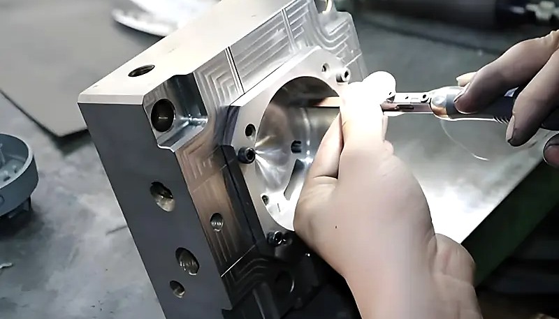
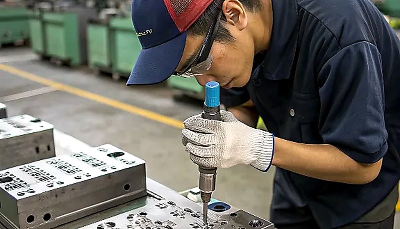
Kalıp üretimi için hassas CNC ekipmanlarını kullanan kalıp ustası
Standart enjeksiyon kalıplama, doğru tasarlanmış kalıplar ve kararlı proses koşullarıyla 25 mm’nin altındaki ölçülerde sürekli olarak artı veya eksi 0,05 ila 0,10 mm tolerans sağlar. Optimize edilmiş giriş tasarımı, kontrollü soğutma ve sıkı proses izleme kullanılan hassas kalıplama, iyi tasarlanmış parçalardaki kritik boyutsal özelliklerde artı veya eksi 0,025 mm’ye ulaşabilir. Daha büyük ölçülerin toleransları yaklaşık olarak orantılı biçimde artar; 100 mm’nin üzerindeki ölçülerde tipik değer artı veya eksi 0,1 ila 0,3 mm’dir. Tüm üretim serisi boyunca bu tolerans hedeflerinin güvenilir ve tutarlı biçimde karşılanması için kalıp, malzemeye özgü uygun çekme telafisiyle tasarlanmalıdır.
Enjeksiyon kalıplama hangi toleranslara ulaşabilir?
Kalıp akış simülasyonu, herhangi bir çelik kesilmeden önce erimiş plastiğin kalıp gözünü tam olarak nasıl dolduracağını, kaynak çizgilerinin nerede oluşacağını ve parçanın nasıl çekip çarpılacağını öngörür. Böylece kalıp üretip T1 numunesinde sorunlar görüldükten sonra değiştirmeye dayalı pahalı deneme-yanılma yaklaşımı ortadan kalkar. Çelik değişiklikleri genellikle her değişiklik turuna 2–4 hafta ve $2,000–$10,000+ ekler. Profesyonel kalıp atölyeleri her üretim kalıbında standart tasarım adımı olarak simülasyon çalıştırır; çünkü tek bir simülasyonun maliyeti, tek bir çelik değişikliğinin bile çok küçük bir kısmıdır.
Kalıp üretilmeden önce kalıp akış simülasyonu neden önemlidir?
Kalıp akış simülasyonu, çelik işlenmeden önce eriyik plastiğin gözü nasıl dolduracağını, kaynak çizgilerinin yerini ve parçanın nasıl çekip çarpılacağını öngörür. Bu, kalıp üretip T1 numunesinde sorun görülünce değiştiren pahalı deneme-yanılmayı kaldırır. Çelik değişiklikleri tur başına genellikle 2–4 hafta ve $2,000–$10,000+ ekler. Profesyonel kalıpçılar her üretim kalıbında standart olarak simülasyon yapar; bir simülasyonun maliyeti tek çelik değişikliğinin küçük bir bölümüdür.
Bir enjeksiyon kalıbı hangi bakımları gerektirir?
Üretim kalıpları, parça kalitesini korumak ve takımın faydalı ömrünü uzatmak için düzenli aralıklarla planlı bakım gerektirir. Temel bakım görevleri; yüzey kalitesini geri kazandırmak için her 50,000–100,000 çevrimde kavite temizliği ve polisajı, itici pim denetimi ve yağlaması, termal performansı korumak için soğutma kanallarındaki kirecin giderilmesi, erozyon hasarı açısından yolluk girişi bölgesinin denetimi (özellikle cam elyaf dolgulu malzemelerde önemlidir) ve sürgü ile eğik itici mekanizmalarının aşınma açısından kontrolüdür. Disiplinli bir önleyici bakım programı kalıp hizmet ömrünü genellikle 2–3 kat uzatır ve pahalı plansız üretim duruşlarını önler.
MOLDFLOW simülasyonu: Moldflow, Autodesk tarafından geliştirilen; enjeksiyon kalıplama sürecindeki polimer akışını, soğumayı ve çekme davranışını öngörmek için sonlu elemanlar analizinden yararlanan bir plastik enjeksiyon kalıplama simülasyon yazılımıdır. ↩
Üretilebilirlik için Tasarım (DFM): DFM; başarılı enjeksiyon kalıplama sağlamak amacıyla duvar kalınlığının eşitliği, kalıp çıkış açıları, nervür oranları ve ters açıların azaltılması gibi unsurları dikkate alarak parçaları kolay ve uygun maliyetli üretilecek biçimde tasarlama uygulamasıdır. ↩
Elektro Erozyonla İşleme (EDM): EDM, elektrot ile iş parçası arasındaki kontrollü elektrik kıvılcımlarıyla malzeme kaldıran ve sertleştirilmiş çelikte geleneksel kesici takımlarla elde edilemeyen karmaşık geometriler üretebilen hassas bir işleme yöntemidir. ↩