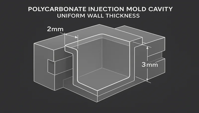
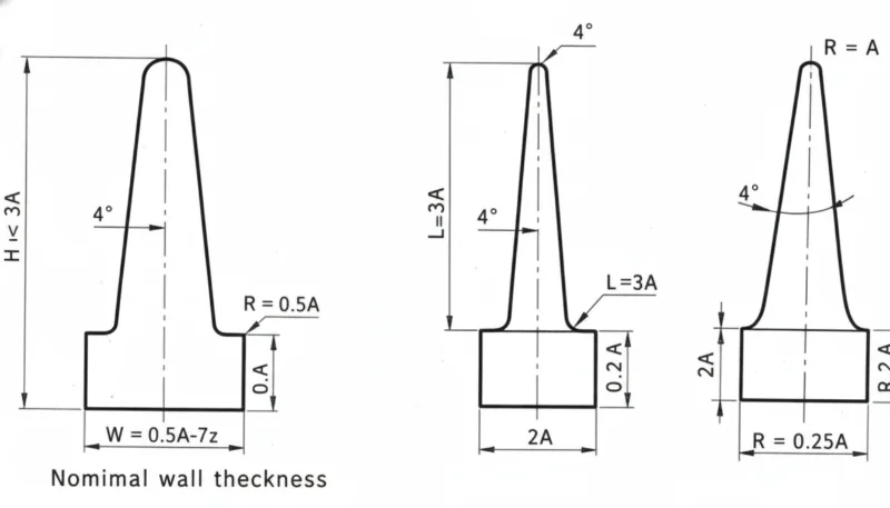
- Eşit cidar kalınlığı en etkili DFM parametresidir; dolumu, soğutmayı, çevrim süresini ve parça mukavemetini aynı anda kontrol eder.
- Malzemeye özgü minimum değerler: ABS 1.0–3.5mm, PC 1.0–4.0mm, PA6 0.8–3.0mm, PP 0.8–3.8mm, PEEK 0.4–6.5mm.
- Çökme izlerini ve çarpılmayı önlemek için nervürler nominal cidar kalınlığının %50–60'ı kadar olmalı ve yükseklikleri cidar kalınlığının 3×'ini aşmamalıdır.
- Her cidar kalınlığı geçişinde gerilme yığılmalarını ve birleşme çizgilerini önlemek için en az 3:1 (uzunluk:kalınlık değişimi) koniklik gerekir.
- ZetarMold'un DFM denetimi, duvar kalınlığı ihlallerinin ilk numune hatalarının %40+'ından sorumlu olduğunu gösteriyor — bunları çelik işlenmeden önce yakalamak kalıp başına $5,000–$25,000 tasarruf sağlar.
Enjeksiyon Kalıplamada Cidar Kalınlığı Neden Her Şeyi Kontrol Eder?
Bir tasarım mühendisi bir keresinde bize aynı kısımda duvarları 0,8 mm’den 6,2 mm’ye kadar değişen bir PC muhafazası getirmişti. Tutarlı bir döngü süresi elde edene kadar araç üç hafta çalıştı. Sorunun tamamı duvar kalınlığının değişmesiydi. Duvarlar düzgün olmadığında, önce ince bölümler donar ve akışı daha kalın alanlara kısıtlar; bu da kısa çekimlere, batma izlerine ve öngörülemeyen çarpıklıklara neden olur. Enjeksiyon kalıplama prosesinin tam içeriği için bkz. Enjeksiyon Kalıplama Komple Kılavuzu.
Düzgün duvar kalınlığı kozmetik bir tercih değildir. Doldurma basıncını, soğutma homojenliğini, çevrim süresini ve yapısal performansı yönetir. termoplastikler1 soğudukça küçülürler ve düzgün olmayan soğutma farklılık yaratır büzülme2 — çarpıklığın temel nedeni. CAD’de iyi görünen parçalar, tasarım aşamasından itibaren duvar kalınlığı kontrol edilmezse yapısal olarak sağlam ve boyutsal olarak dengesiz olabilir. Kalıp tasarımı spesifikasyonları ve takım kararları için, bkz. Enjeksiyon Kalıbı Komple Kılavuz.
ZetarMold'da duvar kalınlığı ihlalleri, inceleme kuyruğumuzdaki ilk parça DFM başarısızlıklarının 40%+'sını oluşturur. En yaygın hata, nervürlerin önerilen 50–60% yerine nominal duvarın 100%'ü kalınlığında tasarlanmasıdır; bu durum ilk 500 baskı içinde Class-A yüzeylerde çökme izlerine yol açar. Bunu DFM incelemesinde yakalamak 4 saat sürer; T1 sonrasında düzeltmek ise 2–4 hafta ve çelik işlemede $3,000–$8,000 maliyet gerektirir.
Yaygın Enjeksiyon Kalıplama Malzemelerinde Duvar Kalınlığı Aralıkları Nelerdir?
Her termoplastiğin eriyik viskozitesi, ısıl iletkenliği ve büzülme oranıyla belirlenen işlenebilir bir et kalınlığı aralığı vardır. Bu aralığın dışında ya eksik dolum (çok ince) ya da aşırı çöküntü izi ve çevrim süresi (çok kalın) oluşur. Bu aralıklar standart işleme koşullarını varsayar; yüksek enjeksiyon hızına ve optimize edilmiş takımlara sahip ince cidar uygulamaları minimum değerlerin altına inebilir.
| Malzeme | En az (mm) | Tipik (mm) | Maks. (mm) | Notlar |
|---|---|---|---|---|
| ABS | 1.0 | 1.5–3.0 | 3.5 | İyi akış; kozmetik sınıflar çöküntü kontrolü için eşit cidar gerektirir |
| PC | 1.0 | 2.0–3.5 | 4.0 | Yüksek viskozite; keskin köşelerden kaçının, geniş kalıp çıkış açısı gerektirir |
| PA6 (Naylon) | 0.8 | 1.5–3.0 | 3.0 | Higroskopik; işlemeden önce kurutun; eşit kalınlıkta düşük çarpılma |
| PP | 0.8 | 1.5–3.5 | 3.8 | Yüksek büzülme (1.5–2.0%); düzensiz cidarlarda çarpılmaya yatkın |
| PEEK | 0.4 | 1.0–4.5 | 6.5 | Yüksek işlem sıcaklığı (380°C+); mükemmel boyutsal kararlılık |
| PC/ABS | 1.0 | 1.5–3.0 | 3.5 | Dengeli akış/dayanım; muhafazalar için tercih edilir |
| PA66-GF30 | 1.0 | 1.5–3.5 | 4.0 | Dolgusuz malzemeye kıyasla daha az çekme; anizotropik çarpılma riski |
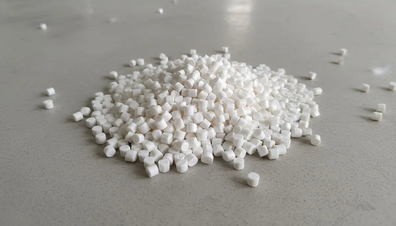
Çöküntü İzlerine Neden Olmadan Nervürler ve Bosslar Nasıl Tasarlanır?
Nervürler, Class-A yüzeylerdeki çökme izlerinin başlıca nedenidir. Kural basit olsa da sıkça ihlal edilir: nervür kalınlığı, nominal cidar kalınlığının 50–60%‘i olmalıdır. 100% cidar kalınlığında nervür tabanı, daha uzun sürede soğuyan yerel bir kalın kesit oluşturur — dış yüzeyden malzeme çekerek görünür bir çöküntü yaratır. 40% veya altında ise nervür yetersiz dolar ve yapısal dayanımı düşük kalır.
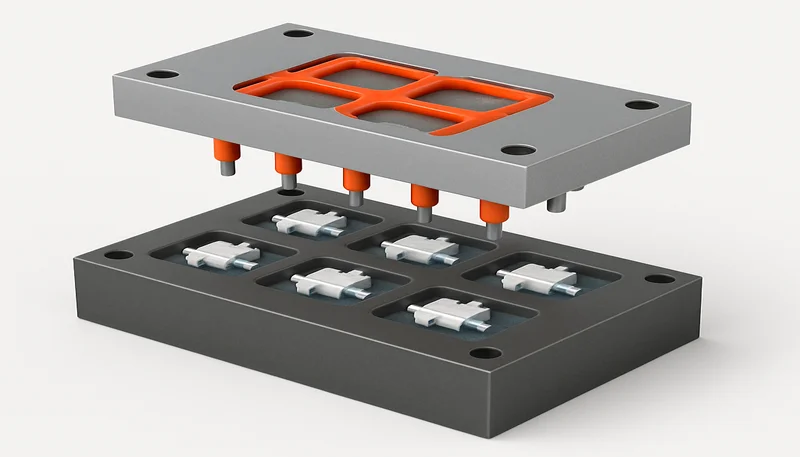
Nervür yüksekliği ikinci bir kısıt getirir: nominal et kalınlığının 3× değerinden yüksek olmamalıdır. Daha yüksek nervürler püskürmeye, yetersiz doluma ve yüksek çıkarma gerilimine yol açar. Kozmetik yüzeylerde nervür yüksekliğini et kalınlığının 2× değeriyle sınırlayın ve çıkarma sırasında çizilmeyi önlemek için draft açısının her yanda en az 0.5° — tercihen 1° — olmasını sağlayın.
Vida yuvalarının dış duvar kalınlığı için de nominal parça duvarına göre aynı 50–60% kuralı geçerlidir. Yuva maçasının çapı vida dişi boyutunu belirler; çöküntü riskini oluşturan dış duvardır. Yuva yüksekliği dış çapının 2× değerini aşıyorsa yuvadan yakındaki bir yapısal duvara feder ekleyin; desteklenmeyen yuvalar montaj sırasında tork yükü altında çatlar.
Duvar Kalınlığı Geçişleri Fazla Keskin Olursa Ne Olur?
Ani cidar geçişleri aynı anda iki sorun oluşturur: akış duraksaması ve gerilim yoğunlaşması. Eriyik, ince bir kesitten sonra aniden kalın bir kesite ulaştığında duraksayarak birleşme izi veya soğuk tapa oluşturabilir. Kalın bir kesitten sonra ince bir kesit geldiğinde ise ince kesit önce donar ve hâlâ soğuyan kalın kesiti kısıtlar; bu da parça itildikten sonra çarpılmasına yol açan artık gerilim oluşturur.
Tasarım kuralı en az 3:1 oranında koniktir; her 1 mm kalınlık değişikliği için 3 mm konik uzunluğuna izin verin. Kritik yapısal parçalar veya optik bileşenler için 5:1 veya daha fazlasını kullanın. kalıp akış analizi3 çelik kesilmeden önce ani geçişleri güvenilir bir şekilde tanımlar; Bitişik duvar bölümleri arasında 2:1’in üzerindeki herhangi bir kalınlık oranı, bir akış simülasyonu incelemesini tetiklemelidir.
Et Kalınlığı Çevrim Süresini ve Maliyeti Nasıl Etkiler?
Çevrim süresinde soğutma süresi belirleyicidir ve soğutma süresi et kalınlığının karesiyle ölçeklenir. 3mm et kalınlığına sahip bir parçanın soğuması, 1.5mm et kalınlığındaki parçaya göre yaklaşık 4× daha uzun sürer; 2× değil. Enjeksiyon kalıplama ekonomisindeki en önemli formül budur: et kalınlığının iki katına çıkarılması soğutma süresini dört katına çıkarır ve bu da yüksek hacimde birim maliyeti doğrudan katlar.
Kalın cidarların gerekli göründüğü yapısal muhafazalarda bunun yerine nervürlerle güçlendirilmiş ince cidarları değerlendirin. Doğru tasarlanmış nervürlere sahip 1.5mm cidar, yarı çevrim süresinde 3.0mm dolu cidarın yapısal performansına ulaşabilir. Nervürlü tasarımın takım maliyetindeki artış genellikle $2,000–$5,000’dir; yılda 500,000 parçada yalnızca çevrim süresindeki azalmadan sağlanan tasarruf çoğu zaman yıllık $80,000’i aşar.
Parçanız İçin Optimum Et Kalınlığı Nasıl Hesaplanır?
Fabrikamızda bir PC/ABS muhafaza programında et kalınlığını 3.0mm'den 1.8mm'ye düşürmek, çevrim süresini 48 saniyeden 31 saniyeye indirerek 35% azalma sağladı. 4 gözlü bir kalıpta yılda 400,000 parça üretiminde bu değişiklik müşteriye makine süresinden yılda $62,000 tasarruf sağlarken, nervürlerle güçlendirilmiş 1.8mm et, orijinal 3.0mm tasarımla aynı yapısal düşürme testi gerekliliklerini karşıladı.
Aşırı kalın duvarların maliyet cezası üretim hacminde katlanır. Duvar kalınlığının 2.5mm’den 2.0mm’ye 0.5mm azaltılması soğutma süresini 36% düşürür. Yılda 2 milyon parça üreten 16 kaviteli bir takımda çevrim süresindeki bu 36% azalma, makine süresinde yılda $40,000–$80,000 tasarruf sağlayabilir. Duvar kalınlığı ayarı için takım değişikliği maliyeti genellikle $500–$2,000’dır; T1 öncesinde yapılabilecek en yüksek ROI’li değişikliklerden biridir.
Kalın kesitlere göre yolluk girişi konumu, et kalınlığı eşitliğinden sonraki ikinci kritik parametredir. Yolluk girişini en kalın kesite yerleştirmek, kalın kesit donmadan önce dolum basıncının ince alanlara ulaşmasını sağlar. İnce bir kesitten giriş yapmak, kalın bölgelerde duraksama izlerine ve eksik doluma neden olur. Kalıp akış analizi, yolluk girişine yakın ve uzak kesitler arasındaki et oranının 1.5:1’i aştığı her tasarımda giriş konumunu doğrular.
“Homojen cidar kalınlığı, kalıp imalatı onayından önce uygulanabilecek en yüksek yatırım getirili DFM değişikliğidir.”True
Cidar kalınlığının tekdüzeliği dolumu, soğutmayı, çekmeyi, çevrim süresini ve yapısal performansı aynı anda etkiler. Tekdüze cidarı zorunlu kılan bir DFM denetimi — genellikle 4 saatlik bir mühendislik incelemesi — ilk parça başarısızlığının en yaygın nedenlerini önler. Fabrikamızda DFM incelemesinde tespit edilen cidar kalınlığı düzeltmeleri, kalıp başına ortalama 2.3 revizyon turunu önler; bu da $6,000–$20,000 değerinde çelik yeniden işleme maliyetinden kaçınılmasını sağlar.
“Daha kalın duvarlar her zaman daha güçlü enjeksiyonla kalıplanmış parçalar üretir.”False
Malzemeye özgü optimum kalınlık aralıklarının ötesinde, ek duvar kalınlığı orantılı bir dayanım artışı sağlamadan ağırlığı ve çevrim süresini artırır. Çoğu mühendislik termoplastiğinde yapısal verim 1.5–3.0mm aralığında en yüksektir. Bu aralığın üzerinde baskın arıza biçimleri malzeme dayanımından artık gerilime, çarpılmaya ve çökme izlerine kayar; bunların tümü etkin yük taşıma performansını düşürür. Federli ince duvar tasarımları, hem dayanım/ağırlık oranında hem de boyutsal kararlılıkta masif kalın duvarlı eşdeğerlerden sürekli daha iyi performans gösterir.
Et kalınlığı kararları tüm imalat prosesi boyunca zincirleme etki yaratır. 1.5mm yeterliyken 3.0mm et kalınlığıyla tasarlanan bir parça, 4× soğutma süresi cezası taşır ve bu ceza her üretim çalışmasında birikir. Kalıp akış analizi bu ödünleşimleri takım onayından önce nicelendirerek mühendislik ekiplerine ihtiyatlı aşırı tahminler yerine bilinçli kalınlık kararları almaları için veri sağlar. Bu dinamikleri T0 sonrasında değil, konsept tasarım aşamasında erkenden hesaba katmak; programa uygun ilerleyen bir programla ölçü kararlılığı peşinde aylarca revizyon çevrimi harcayan bir program arasındaki farktır.
“Kalıp akış analizi, T1 numuneleri kesilmeden önce et kalınlığıyla ilgili kusurları öngörebilir.”True
Modern kalıp akış simülasyonu; et kalınlığı değişiminin yol açtığı dolum basıncını, kaynak çizgisi konumunu, çökme izi derinliğini ve çarpılma miktarını doğru biçimde öngörür. Kalıp akış analizi, çelik kesilmeden önce kalınlık kaynaklı kusurların 80%+ bölümünü simülasyon çalışması başına $500–$2,000 maliyetle yakalar. Yılda 100,000 parçanın üzerindeki üretim programlarında kalıp akış analizi, en az bir T1 revizyon çevrimini ortadan kaldırarak her programda pozitif ROI sağlar.
"Nominal duvar kalınlığına eşit nervür kalınlığı, kozmetik olmayan yüzeyler için kabul edilebilir."False
Aşırı kalın nervürlerden kaynaklanan çökme izleri sadece yüzey görünümüyle sınırlı değildir — iç gerilim yaratan ve yorulma ömrünü azaltan lokalize büzülme farklılıklarına işaret ederler. Kozmetik olmayan yüzeylerde bile, 0% duvar kalınlığındaki nervürler, montaj uyumunu etkileyen boyutsal varyasyona neden olur. –60% nervür kalınlığı kuralı, kozmetik sınıflandırmasından bağımsız olarak geçerlidir; tek istisna, Sonlu Elemanlar Analizi ile doğrulanan yük taşıyıcı uygulamalardaki yapısal nervürlerdir.
Enjeksiyon Kalıp Duvar Kalınlığı Hakkında Sıkça Sorulan Sorular
Enjeksiyon kalıplama için minimum duvar kalınlığı nedir?
Minimum duvar kalınlığı malzemeye ve parça geometrisine bağlıdır. Standart ABS ve PC için geleneksel takımla pratik minimum 1.0mm’dir. Naylon (PA6/PA66) ve PP için, optimize edilmiş geçit tasarımı ve yüksek enjeksiyon hızıyla 0.8mm elde edilebilir. PEEK ve LCP, özel ince duvarlı takımlarda 0.4mm’ye ulaşabilir. Minimum kalınlığın altında, eriyik boşluğu tamamen doldurmadan donar ve kısa dolum oluşturur. Fabrikamızda, % üzerinde dolum güvenini doğrulamak için takım yetkilendirmesinden önce 1.2mm altındaki her duvar kalınlığını kalıp akış analiziyle doğrularız.
Duvar kalınlığı büzülme ve eğrilmeyi nasıl etkiler?
Düzgün olmayan duvar kalınlığı, farklı büzülmeye neden olur — kalın kesitler daha yavaş soğur ve ince kesitlerden daha fazla büzülür. Bu farklı büzülme, çıkarma sonrası parçayı eğen iç gerilim üretir. PP ve PA6 gibi yarı kristal malzemelerde, büzülme kalın kesitlerde 1.5–2.5%‘ye ulaşabilirken ince kesitlerde 0.5–1.0%‘dir — bu 3 kat fark, karışık duvar kalınlıklarına sahip parçalarda önemli eğrilme yaratır. Çözüm, –15% varyasyon içinde düzgün duvar kalınlığı ve dengeli soğutmayı doğrulamak için kalıp akış analizi ile desteklenmesidir. Eğrilme simülasyonu, kalıp yapılmadan önce sapma büyüklüğünü doğru şekilde tahmin eder.
Değişken duvar kalınlığına sahip parçaları enjeksiyonla kalıplayabilir misiniz?
Evet, ancak varyasyon kademeli geçişlerle yönetilmelidir. Tasarım kuralı 3:1 koniklik oranıdır — her 1mm kalınlık değişimi için 3mm koniklik uzunluğu. Ani geçişler akış tereddüdü, kaynak çizgileri ve kalıntı gerilim yaratır. Kritik optik veya yapısal parçalar için 5:1 veya daha yüksek oran kullanın. Tek bir parça içinde duvar kalınlığı 50%‘den fazla değiştiğinde kalıp akış analizi şarttır. Fabrikamızda, DFM onayından önce zorunlu akış simülasyonu için duvar oranı 2:1’in üzerinde olan her tasarımı işaretleriz.
Enjeksiyonla kalıplanmış parçalar için ideal kaburga-duvar kalınlığı oranı nedir?
Standart oran nominal duvar kalınlığının –60%‘sidir. 2.0mm nominal duvar için, nervürler tabanda 1.0–1.2mm kalınlığında olmalıdır. % veya üzerinde, ilk 100–500 üretim atışı içinde karşı yüzeyde çökme izleri görünür hale gelir. % veya altında, nervürler zayıf dolar ve yeterli yapısal yük taşımaz. Nervür yüksekliği nominal duvarın 3 katını geçmemelidir; eğim açısı yan başına en az 0.5° olmalıdır. Bu kurallar malzemeden bağımsız olarak geçerlidir — büzülme kaynaklı çökme izi oluşumunun fiziği ABS, PC, naylon ve PP için aynıdır.
Et kalınlığı enjeksiyon kalıplama maliyetini ne ölçüde etkiler?
Duvar kalınlığı, döngü süresi aracılığıyla maliyet üzerinde doğrudan ve önemli bir etkiye sahiptir. Soğuma süresi — enjeksiyon kalıplama döngü süresinin baskın bileşeni — duvar kalınlığının karesiyle ölçeklenir. 3.0mm duvarlı bir parça, 1.5mm’deki aynı parçadan yaklaşık 4 kat daha uzun sürede soğur, bu da üretim hacminde birim maliyeti doğrudan çarpar. Yılda 500.000 parçada, bu fark yıllık üretim maliyetinde $60.000–$120.000’yi temsil edebilir. Ayrıca, 1.0mm altı veya 4.0mm üstü duvarlar özel takım ve işlem gerektirir, bu da başlangıç takım maliyetine $5.000–$20.000 ekler.
Duvar kalınlığı soğuma süresini ve döngü maliyetini nasıl etkiler?
Soğuma süresi yaklaşık olarak duvar kalınlığının karesiyle ölçeklenir — duvar kalınlığını ikiye katlamak soğuma süresini kabaca dört katına çıkarır, bu da döngü süresini ve parça başı maliyeti doğrudan artırır. Bu nedenle düzgün duvar kalınlığını korumak hem yapısal hem de üretim verimliliği gereğidir. Kalın kesitler sadece çökme izleri ve eğrilme riski taşımakla kalmaz, aynı zamanda kalıplama döngüsünü önemli ölçüde uzatarak pres çıktısını vardiya başına düşürür.
- Rosato, D.V. ve Rosato, M.G. Enjeksiyon Kalıplama El Kitabı, 3. baskı. Springer, 2000 — Termoplastikler için duvar kalınlığı tasarım ilkeleri.
- Harper, CA (ed.) Plastik Teknolojileri El Kitabı. McGraw-Hill, 2006 — malzemeye özgü işleme aralıkları ve büzülme verileri.
- Bryce, DM. Plastik Enjeksiyon Kalıplama: Kalıp Tasarımı ve Yapımının Temelleri. SME, 1998 — Diş ve göbek tasarım kuralları, koniklik oranları.
termoplastikler: Termoplastikler ısıtıldığında eriyen ve soğutulduğunda katılaşarak tekrar tekrar işlenmeye olanak sağlayan polimerlerdir. ABS, PC, PA6, PP ve yüzlerce mühendislik sınıfını kapsayan enjeksiyon kalıplama için baskın malzeme sınıfıdırlar. ↩
büzülme: Büzülme, kalıplanmış bir parçanın erime sıcaklığından oda sıcaklığına soğurken maruz kaldığı hacimsel azalmayı ifade eder. Eşit olmayan duvar kalınlığından kaynaklanan eşit olmayan büzülme, çarpıklık ve çökme izlerinin ana nedenidir. ↩
kalıp akış analizi: Kalıp akışı analizi, çelik kesilmeden önce plastik eriyik akışını, soğumayı ve kalıp boşluğu içindeki büzülmeyi modelleyen bir bilgisayar simülasyonudur. Duvar kalınlığı değişiminden kaynaklanan dolgu dengesizliklerini, kaynak hatlarını ve termal sıcak noktaları tanımlar. ↩