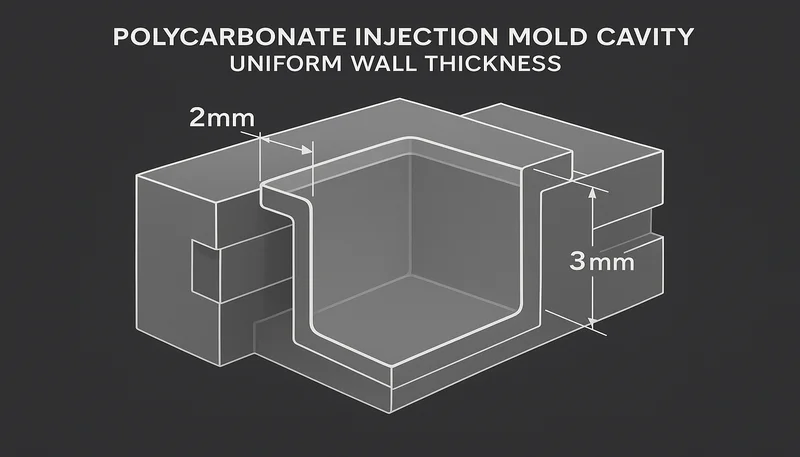
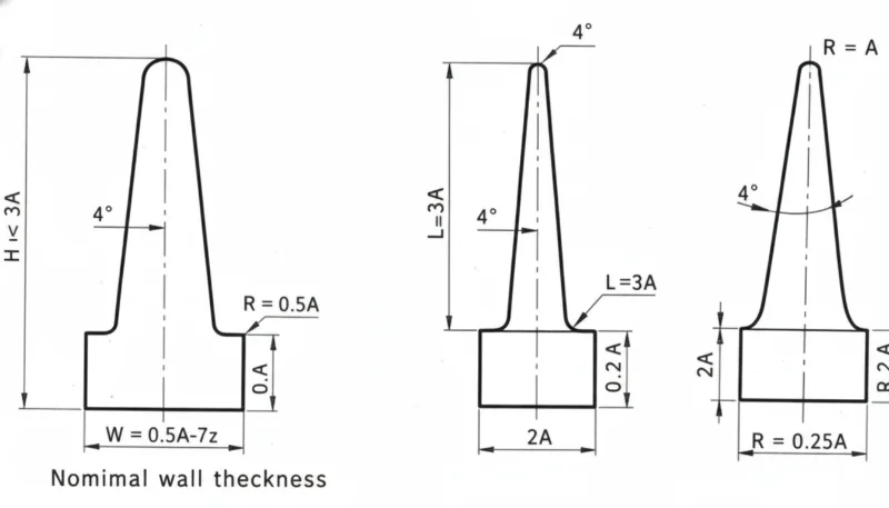
- Uniforme wanddikte is de single meest impactful DFM parameter — het controleert fill, cooling, cyclustijd, en deel sterkte simultaneously.
- Materiaal-specifieke minimums: ABS 1.0–3.5mm, PC 1.0–4.0mm, PA6 0.8–3.0mm, PP 0.8–3.8mm, PEEK 0.4–6.5mm.
- Ribben moeten 50–60% van de nominale wanddikte zijn en niet hoger dan 3× de wand om zinkmarkeringen en vervorming te voorkomen.
- Elke wanddikte-overgang vereist een tapsheid van minimaal 3:1 (lengte:dikteverandering) om spanningsconcentraties en naadlijnen te vermijden.
- ZetarMold’s DFM audit shows wanddikte violations account voor 40%+ van first-article failures — catching them voor steel cuts saves $5,000–$25,000 per mold.
Waarom Controleert Wanddikte Alles in Spuitgieten?
Een ontwerpingenieur bracht ons ooit een pc-behuizing met wanden variërend van 0,8 mm tot 6,2 mm in hetzelfde onderdeel. De tool draaide drie weken voordat we een consistente cyclustijd konden aanhouden. Variatie in de wanddikte was het hele probleem. Wanneer muren oneffen zijn, bevriezen dunnere delen het eerst en beperken ze de stroming naar dikkere gebieden, wat korte schoten, zinksporen en onvoorspelbare kromtrekking veroorzaakt. Voor de volledige context van het spuitgietproces, zie onze Injection Moulding Complete Guide.
Een uniforme wanddikte is geen cosmetische voorkeur. Het regelt de vuldruk, uniformiteit van de koeling, cyclustijd en structurele prestaties. thermoplasten1 trekken samen terwijl ze afkoelen, en niet-uniforme koeling zorgt voor differentiële krimp2 — de hoofdoorzaak van kromtrekken. Onderdelen die er goed uitzien in CAD kunnen structureel ondeugdelijk en dimensionaal onstabiel zijn als de wanddikte niet vanaf de ontwerpfase wordt gecontroleerd. Voor matrijsontwerpspecificaties en gereedschapsbeslissingen, zie onze Injection Mould Complete Guide.
Bij ZetarMold vormen wanddikte-overtredingen 40%+ van de eerste DFM-fouten in onze reviewwachtrij. De meest voorkomende fout: ribben ontworpen op 100% van de nominale wand — niet de aanbevolen 50–60% — wat zinkmarkeringen veroorzaakt op Klasse-A oppervlakken binnen de eerste 500 shots. Dit opvangen in DFM-review kost 4 uur; repareren na T1 kost 2–4 weken en $3,000–$8,000 in staalrework.
Wat zijn de Wanddikte Ranges voor Gemeenschappelijke Spuitgietmaterialen?
Elke thermoplast heeft een procesbare wanddikte range bepaald door melt viscositeit, thermische conductiviteit en shrinkage rate. Buiten deze range krijg je short shots (too thin) of excessive sink marks en cyclusduur (too thick). Deze ranges assumeren standaard processing condities; thin-wall applicaties met hoog injectie snelheid en optimized gereedschap kunnen push onder de minimums.
| Materiaal | Min. (mm) | Typisch (mm) | Maximum (mm) | Opmerkingen |
|---|---|---|---|---|
| ABS | 1.0 | 1.5–3.0 | 3.5 | Goede stroming; cosmetische kwaliteiten vereisen uniforme wand voor sink controle |
| PC | 1.0 | 2.0–3.5 | 4.0 | Hoge viscositeit; vermijd scherpe hoeken, vereist ruim draft |
| PA6 (nylon) | 0.8 | 1.5–3.0 | 3.0 | Hygroscopisch; droog voor verwerking; lage vervorming bij uniforme dikte |
| PP | 0.8 | 1.5–3.5 | 3.8 | Hoog shrinkage (1.5–2.0%); vervorming-prone met non-uniform wanden |
| PEEK | 0.4 | 1.0–4.5 | 6.5 | Hoog processing temp (380°C+); excellent dimensional stability |
| PC/ABS | 1.0 | 1.5–3.0 | 3.5 | Balanced flow/strength; voorkeur voor enclosures |
| PA66-GF30 | 1.0 | 1.5–3.5 | 4.0 | Verminderde krimp versus ongevuld; risico op anisotrope vervorming |
Hoe Ontwerp Ribben en Bosses Zonder Sink Marks te Creëren?
Ribben zijn de leading cause van sink marks op Class-A surfaces. De regel is simple maar frequent violated: rib thickness moet 50–60% van nominale wanddikte zijn. Bij 100% wanddikte, de rib base creëert een localized dik sectie die longer neemt om te coolen — pulling materiaal van de outer surface en creëert een visible depression. Bij 40% of minder, de rib vult poorly en heeft insufficient structurele strength.
Rib hoogte voegt een tweede beperking toe: niet hoger dan 3× de nominale wanddikte. Hoger ribben veroorzaken jetting, slechte vulling en hoog ejectie stress. Voor cosmetische oppervlakken, beperk rib hoogte tot 2× wand en zorg dat de draft hoek minimaal 0.5° per zijde is — 1° voorkeur — om scoring tijdens ejectie te voorkomen.
Bosses follow dezelfde 50–60% rule voor outer wanddikte relative to de nominale deel wand. De boss core diameter bepaalt de screw thread size; de outer wand is wat sink risk creëert. Add een rib van de boss naar een nearby structurele wand if de boss height exceeds 2× zijn outer diameter — unsupported bosses crack onder torque loading in assembly.
Wat gebeurt er als wanddikte-overgangen te abrupt zijn?
Abrupt wand transitions creëren twee problems simultaneously: flow hesitation en stress concentration. Wanneer melt hits een sudden thick section na een thin one, kan het hesitate en een weld line of cold slug creëren. Wanneer een thin section follows een thick one, de thin section freezes eerst en constrains de still-cooling thick section — generating residual stress dat warps het deel na ejection.
De ontwerpregel is een tapsheid van minimaal 3:1; voor elke dikteverandering van 1 mm moet u rekening houden met een tapsheid van 3 mm. Gebruik voor kritische structurele onderdelen of optische componenten een verhouding van 5:1 of hoger. vormstroomanalyse3 identificeert op betrouwbare wijze abrupte overgangen voordat staal wordt gesneden; elke dikteverhouding boven 2:1 tussen aangrenzende muursecties zou aanleiding moeten geven tot een beoordeling van de stromingssimulatie.
Hoe Beïnvloedt Wanddikte de Cyclusduur en Kosten?
Cyclustijd wordt gedomineerd door koeltijd, en koeltijd schaalt met het kwadraat van wanddikte. Een deel met 3mm wanden kost ongeveer 4× meer tijd om te koelen dan een 1.5mm wanddeel — niet 2×. Dit is de belangrijkste formule in spuitgiet-economie: verdubbeling van wanddikte verviervoudigt koeltijd, wat direct de unitkost vermenigvuldigt bij grote volumes.
Voor structurele behuizingen waar dikke wanden nodig lijken, overweeg rib-versterkte dunne wanden. Een wand van 1,5 mm met goed ontworpen ribben kan de structurele prestaties van een massieve wand van 3,0 mm evenaren bij de helft van de cyclusduur. De gereedschapskostenstijging voor een geribbeld ontwerp is typisch $2.000–$5.000; de besparingen bij 500.000 onderdelen/jaar overschrijden vaak $80.000 per jaar alleen al in cyclusduurreductie.
Hoe Bereken Optimal Wanddikte voor Je Deel
Bij onze fabriek, switching van 3.0mm naar 1.8mm wanddikte op een PC/ABS enclosure programma reduceerde cyclustijd van 48 seconden naar 31 seconden — een 35% reductie. Bij 400,000 delen/jaar op een 4-cavity tool, dit saved de klant $62,000 annually in machine tijd, terwijl de rib-versterkte 1.8mm wand dezelfde structurele drop-test vereisten als de originele 3.0mm design.
De kost penalty van over-dikke wanden componeert bij productievolume. Een 0.5mm reductie in wanddikte — van 2.5mm naar 2.0mm — reduceert koeltijd door 36%. Op een 16-cavity tool running 2 miljoen delen per jaar, die 36% cyclustijd reductie kan $40,000–$80,000 annually in machine tijd besparen. De tooling modificatie kost voor een wanddikte adjustatie is typisch $500–$2,000 — een van de hoogste ROI changes available voor T1.
Gate locatie relatief tot dikke secties is de tweede kritische parameter na wanddikte uniformiteit. Plaatsing van gate bij de dikste sectie zorgt dat vullingsdruk dunne areas bereikt voor de dik sectie bevriest. Gating in een dun sectie veroorzaakt hesitation marks en incomplete vulling in dik zones. Mold flow analyse verifieert gate positie voor elk ontwerp waar wand ratio meer dan 1.5:1 tussen gate-proximale en gate-distale secties.
“Uniforme wanddikte is de hoogste ROI DFM-verandering die beschikbaar is voor de autorisatie van gereedschap.”True
Wanddikte-uniformiteit beïnvloedt vulling, koeling, krimp, cyclusduur en structurele prestaties gelijktijdig. Een DFM-audit die uniforme wanddikte afdwingt – typisch een technische beoordeling van 4 uur – voorkomt de meest voorkomende oorzaken van eerste-artikelfalen. In onze fabriek besparen wanddiktecorrecties die in DFM-beoordelingen worden opgemerkt gemiddeld 2,3 revisieronden per matrijs, wat $6.000–$20.000 aan staalbewerkingskosten scheelt.
“Dikker wanden produceren altijd sterker spuitgietdeel.”False
Beyond materiaal-specifieke optimal thickness ranges, additional wanddikte voegt weight en cyclusduur zonder proportional strength gain. Structurele efficiency peaks bij 1.5–3.0mm voor meeste engineering thermoplastics. Above deze range, de dominant failure modes shift van materiaal strength naar residual stress, vervorming en sink marks — alle welke reduce effective load-bearing performance. Ribbed thin-wall ontwerpen consistently outperform solid thick-wall equivalents in beide strength-to-weight ratio en dimensional stability.
Wanddikte beslissingen cascade door het hele productieproces. Een deel ontworpen met 3.0mm wanden waar 1.5mm voldoende zou zijn, draagt 4× de koeltijd penalty — en die penalty componeert over elke productierun. Moldflow analyse quantificeert deze tradeoffs voor tooling autorisatie, geeft engineering teams de data om geïnformeerde dikte beslissingen te maken, niet conservatieve overestimates. Accounting voor deze dynamiek vroeg — in het concept design fase, niet na T0 — is het verschil tussen een programma dat op schema loopt en een dat maanden in revision cycles spendeert chasing dimensionale stabiliteit.
“Mold flow-analyse kan wanddikte-gerelateerde defecten voorspellen voordat T1-monsters worden gesneden.”True
Moderne moldflow simulatie accurately predicts fill druk, weld line locatie, sink mark depth, en warpage magnitude caused door wanddikte variatie. Moldflow analyse catches 80%+ van thickness-related defects voor steel is cut, at een kost van $500–$2,000 per simulatie run. Voor productie programma boven 100,000 delen/jaar, moldflow analyse delivers positive ROI op elke programma door eliminating at least één T1 revision cycle.
“Rib dikte gelijk aan nominale wanddikte is acceptabel voor niet-cosmetische oppervlakken.”False
Zinkmarkeringen door overmatig dikke ribben zijn niet beperkt tot oppervlakteverschijning — ze duiden op lokale verschillen in krimp die interne spanning veroorzaken en de levensduur onder vermoeiing verminderen. Zelfs op niet-cosmetische oppervlakken veroorzaken 100% wanddikte ribben dimensionale variatie die de montagefit beïnvloedt. De 50–60% ribdikte regel geldt ongeacht de cosmetische classificatie; de enige uitzondering zijn structurele ribben in draagtoepassingen die door FEA-analyse zijn bevestigd.
Veelgestelde Vragen Over Wanddikte van Spuitgietmatrijzen

Wat is de minimale wanddikte voor spuitgieten?
Minimale wanddikte hangt af van het materiaal en de onderdeelgeometrie. Voor standaard ABS en PC is het praktische minimum 1,0 mm met conventioneel gereedschap. Voor nylon (PA6/PA66) en PP is 0,8 mm haalbaar met geoptimaliseerd poortontwerp en hoge inspuitsnelheid. PEEK en LCP kunnen 0,4 mm bereiken in gespecialiseerd dunwandig gereedschap. Onder de minimale dikte bevriest het smeltmateriaal voordat de holte volledig gevuld is, wat leidt tot onvolledige aanvoer. In onze fabriek valideren we elke wanddikte onder 1,2 mm met spuitgietanalyse vóór gereedschapsautorisatie om een vulzekerheid boven 95% te bevestigen.
Hoe beïnvloedt wanddikte krimp en vervorming?
Niet-uniforme wanddikte veroorzaakt differentiële krimp — dikkere secties koelen langzamer af en krimpen meer dan dunne secties. Deze differentiële krimp genereert interne spanning die het onderdeel na uitwerping vervormt. Voor semicrystallijne materialen zoals PP en PA6 kan de krimp oplopen tot 1,5–2,5% in dikke secties versus 0,5–1,0% in dunne secties — een 3× verschil dat aanzienlijke vervorming veroorzaakt in onderdelen met gemengde wanddiktes. De oplossing is een uniforme wanddikte binnen 10–15% variatie, aangevuld met spuitgietanalyse om een gebalanceerde koeling te bevestigen. Vervormingssimulatie voorspelt nauwkeurig de doorbuigingsgrootte voordat de matrijs wordt gebouwd.
Kun je onderdelen met variërende wanddikte spuitgieten?
Ja, maar variatie moet worden beheerd via geleidelijke overgangen. De ontwerpregel is een 3:1 taper ratio — 3mm taper lengte voor elke 1mm dikteverandering. Abrupte overgangen veroorzaken stromingsweerstand, laslijnen en restspanning. Voor kritische optische of structurele onderdelen gebruik 5:1 of meer. Moldflow analyse is essentieel wanneer wanddikte meer dan 50% varieert binnen één onderdeel. In onze fabriek markeren we elk ontwerp met een wandratio boven 2:1 voor verplichte stromingssimulatie voor DFM-afkeuring.
Wat is de ideale rib-tot-wand dikteverhouding voor spuitgietonderdelen?
De standaard ratio is 50–60% van nominale wanddikte. Voor een 2,0mm nominale wand, ribben moeten 1,0–1,2mm dik zijn aan de basis. Bij 70% of boven, zinkmarkeringen worden zichtbaar op het tegenoverliggende oppervlak binnen de eerste 100–500 productie shots. Bij 40% of onder, ribben vullen slecht en dragen onvoldoende structurele last. Rib hoogte mag niet meer dan 3× de nominale wand zijn; draft hoek moet minimaal 0,5° per zijde zijn. Deze regels gelden ongeacht materiaal — de fysica van krimpgedreven zinkmarkering vorming is hetzelfde voor ABS, PC, nylon, en PP.
Hoe sterk beïnvloedt de wanddikte de spuitgietkosten?
Wanddikte heeft een directe en significante impact op kosten via cyclus tijd. Koeltijd — de dominante component van spuitgietcyclus tijd — schaalt met het kwadraat van wanddikte. Een onderdeel met 3,0mm wanden koelt ongeveer 4× langzamer dan hetzelfde onderdeel bij 1,5mm, wat de stukprijs direct vermenigvuldigt bij productievolume. Bij 500.000 onderdelen/jaar kan dit verschil $60.000–$120.000 in jaarlijkse productiekosten vertegenwoordigen. Bovendien vereisen wanden onder 1,0mm of boven 4,0mm gespecialiseerde gereedschappen en processen, wat $5.000–$20.000 toevoegt aan de initiële gereedschapskosten.
Hoe beïnvloedt wanddikte koeltijd en cyclus kosten?
Koeltijd schaalt ongeveer met het kwadraat van wanddikte — verdubbeling van wanddikte quadrupleert ongeveer de koeltijd, wat direct cyclus tijd en per-onderdeel kosten verhoogt. Uniform wanddikte behouden is dus zowel een structurele als een productie efficiëntie vereiste. Dikke secties riskeren niet alleen zinkmarkeringen en vervorming maar verlengen significant de gietcyclus, verminderen pers output per shift.
- Rosato, D.V. & Rosato, M.G. Handboek voor spuitgieten, 3e druk. Springer, 2000 – ontwerpprincipes voor wanddikte voor thermoplasten.
- Harper, CA (red.) Handboek van kunststoftechnologieën. McGraw-Hill, 2006 – materiaalspecifieke verwerkingsbereiken en krimpgegevens.
- Bryce, D.M. Kunststof spuitgieten: basisprincipes van matrijsontwerp en constructie. SME, 1998 – ontwerpregels voor ribben en naven, conische verhoudingen.
thermoplastische kunststoffen: Thermoplastische kunststoffen zijn polymeren die smelten bij verhitting en stollen bij afkoelen, waardoor herhaalde verwerking mogelijk is. Ze zijn de dominante materiaalklasse voor spuitgieten en omvatten ABS, PC, PA6, PP en honderden technische kwaliteiten. ↩
krimp: Krimp verwijst naar de volumetrische reductie die een gegoten onderdeel ondergaat als het afkoelt van smelttemperatuur naar kamertemperatuur. Niet-uniforme krimp – veroorzaakt door een ongelijkmatige wanddikte – is de belangrijkste oorzaak van kromtrekking en zinksporen. ↩
Mold Flow Analysis: Mold Flow Analysis is een computersimulatie die de smeltstroom, koeling en krimp van plastic in een matrijsholte modelleert voordat staal wordt gesneden. Het identificeert vulonevenwichtigheden, laslijnen en thermische hotspots veroorzaakt door variaties in de wanddikte. ↩