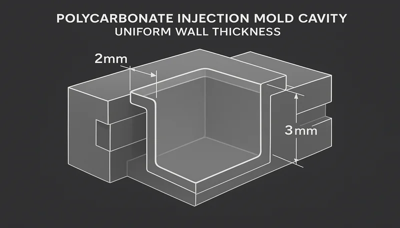
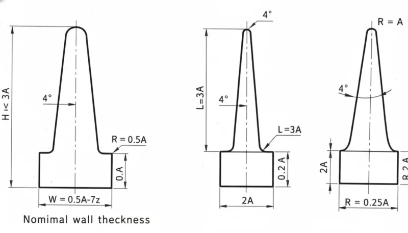
- Jednolita grubość ścianki to najbardziej wpływowy parametr DFM — jednocześnie kontroluje wypełnianie, chłodzenie, czas cyklu i wytrzymałość detalu.
- Minimalne wartości zależne od materiału: ABS 1.0–3.5mm, PC 1.0–4.0mm, PA6 0.8–3.0mm, PP 0.8–3.8mm, PEEK 0.4–6.5mm.
- Żebra muszą mieć 50–60% nominalnej grubości ścianki i wysokość nie większą niż 3× grubość ścianki, aby zapobiec zapadnięciom i wypaczeniom.
- Każde przejście grubości ścianki wymaga stopniowej zmiany o proporcji co najmniej 3:1 (długość:zmiana grubości), aby uniknąć koncentracji naprężeń i linii łączenia.
- Audyty DFM firmy ZetarMold wykazują, że nieprawidłowa grubość ścianek odpowiada za ponad 40% niezgodności pierwszych sztuk — wykrycie tych błędów przed rozpoczęciem obróbki stali pozwala zaoszczędzić 5000–25 000 USD na każdej formie.
Dlaczego grubość ścianki decyduje o wszystkim w formowaniu wtryskowym?
Pewien konstruktor przyniósł nam kiedyś obudowę z PC, której ścianki w tym samym detalu miały od 0.8mm do 6.2mm. Forma pracowała przez trzy tygodnie, zanim uzyskaliśmy stały czas cyklu. Całym problemem była zmienna grubość ścianek. Przy nierównych ściankach cieńsze obszary zestalają się pierwsze i ograniczają dopływ do grubszych — powodując niedolewy, zapadnięcia i nieprzewidywalne odkształcenia. Pełny kontekst procesu zawiera nasz Kompletny przewodnik po formowaniu wtryskowym.
Jednolita grubość ścianek nie jest preferencją estetyczną. Określa ciśnienie wypełniania, równomierność chłodzenia, czas cyklu i właściwości konstrukcyjne. Tworzywa termoplastyczne1 kurczą się podczas chłodzenia, a nierównomierne chłodzenie powoduje różnicowy skurcz2 — główną przyczynę odkształceń. Detale dobrze wyglądające w CAD mogą być konstrukcyjnie wadliwe i niestabilne wymiarowo, jeśli grubość ścianek nie jest kontrolowana od etapu projektowania. Specyfikacje projektowe i decyzje narzędziowe zawiera nasz Kompletny przewodnik po formach wtryskowych.
W ZetarMold nieprawidłowa grubość ścianek odpowiada za ponad 40% negatywnych wyników analizy DFM pierwszych wyprasek trafiających do naszego zespołu. Najczęstszy błąd to żebra zaprojektowane na 100% nominalnej grubości ścianki zamiast zalecanych 50–60%, co powoduje zapadnięcia na powierzchniach klasy A już w ciągu pierwszych 500 cykli. Wykrycie problemu podczas analizy DFM wymaga 4 godzin; jego usunięcie po próbie T1 zajmuje 2–4 tygodnie i kosztuje $3,000–$8,000 za poprawki w stali.
Jakie zakresy grubości ścianek stosuje się w przypadku popularnych materiałów do formowania wtryskowego?
Każde tworzywo termoplastyczne ma określony zakres przetwarzalnej grubości ścianek, wynikający z lepkości stopu, przewodności cieplnej i skurczu. Poza tym zakresem pojawiają się niedolewy (gdy ścianka jest zbyt cienka) albo nadmierne zapadnięcia i wydłużony czas cyklu (gdy jest zbyt gruba). Zakresy te zakładają standardowe warunki przetwórstwa; zastosowania cienkościenne z dużą prędkością wtrysku i zoptymalizowanym oprzyrządowaniem mogą zejść poniżej wartości minimalnych.
| Materiał | Min. (mm) | Typowo (mm) | Maks. (mm) | Uwagi |
|---|---|---|---|---|
| ABS | 1.0 | 1.5–3.0 | 3.5 | Dobra płynność; gatunki do zastosowań estetycznych wymagają równomiernej grubości ścianek, aby ograniczyć zapadnięcia |
| PC | 1.0 | 2.0–3.5 | 4.0 | Wysoka lepkość; unikać ostrych naroży, wymagane duże kąty pochylenia |
| PA6 (nylon) | 0.8 | 1.5–3.0 | 3.0 | Higroskopijny; wymaga suszenia przed przetwarzaniem; małe odkształcenie przy równomiernej grubości |
| PP | 0.8 | 1.5–3.5 | 3.8 | Wysoki skurcz (1.5–2.0%); podatność na odkształcenia przy niejednorodnej grubości ścianek |
| PEEK | 0.4 | 1.0–4.5 | 6.5 | Wysoka temperatura przetwórstwa (380°C+); doskonała stabilność wymiarowa |
| PC/ABS | 1.0 | 1.5–3.0 | 3.5 | Równowaga przepływu i wytrzymałości; preferowane do obudów |
| PA66-GF30 | 1.0 | 1.5–3.5 | 4.0 | Mniejszy skurcz niż w materiale niewzmocnionym; ryzyko anizotropowego paczenia |
Jak projektować żebra i słupki bez powodowania zapadnięć?
Żebra są główną przyczyną zapadnięć na powierzchniach klasy A. Zasada jest prosta, lecz często naruszana: grubość żebra musi wynosić 50–60% nominalnej grubości ścianki. Przy grubości równej 100% grubości ścianki podstawa żebra tworzy miejscowe pogrubienie, które chłodzi się dłużej — odciąga materiał od powierzchni zewnętrznej i powoduje widoczne wgłębienie. Przy grubości 40% lub mniejszej żebro wypełnia się nieprawidłowo i nie zapewnia wystarczającej wytrzymałości konstrukcyjnej.
Wysokość żebra stanowi drugie ograniczenie: nie powinna przekraczać 3× nominalnej grubości ścianki. Wyższe żebra powodują smugi strumieniowe, niedolewy i duże naprężenia podczas wypychania. W przypadku powierzchni estetycznych ogranicz wysokość żebra do 2× grubości ścianki i zapewnij kąt pochylenia wynoszący co najmniej 0.5° na stronę — preferowany jest 1° — aby zapobiec zarysowaniu podczas wypychania.
Gniazda pod wkręty również powinny spełniać zasadę 50–60%: grubość ich ścianki zewnętrznej powinna odpowiadać takiej części nominalnej grubości ścianki wypraski. Średnica rdzenia gniazda określa rozmiar gwintu wkrętu, natomiast ścianka zewnętrzna decyduje o ryzyku powstawania zapadnięć. Jeżeli wysokość gniazda przekracza dwukrotność jego średnicy zewnętrznej, należy połączyć je żebrem z pobliską ścianką konstrukcyjną — niepodparte gniazda pękają pod wpływem momentu dokręcania podczas montażu.
Co się dzieje, gdy zmiany grubości ścianki są zbyt gwałtowne?
Nagłe zmiany grubości ścianek powodują jednocześnie dwa problemy: zahamowanie przepływu i koncentrację naprężeń. Gdy stopione tworzywo po cienkim przekroju trafia nagle do grubego, może zwolnić i utworzyć linię łączenia lub zimny czop. Gdy po grubym przekroju następuje cienki, cienka część zamarza wcześniej i ogranicza nadal stygnącą grubą część, wytwarzając naprężenia szczątkowe, które po wypchnięciu powodują paczenie.
Reguła projektowa wymaga pochylenia co najmniej 3:1 — na każdy 1mm zmiany grubości należy zapewnić 3mm długości przejścia. Dla krytycznych detali konstrukcyjnych lub elementów optycznych stosuj 5:1 lub więcej. Analiza przepływu tworzywa w formie3 niezawodnie wykrywa gwałtowne przejścia przed obróbką stali; każdy stosunek grubości powyżej 2:1 między sąsiednimi ściankami powinien uruchomić analizę symulacji przepływu.
Jak grubość ścianki wpływa na czas cyklu i koszt?
Czas cyklu zależy przede wszystkim od czasu chłodzenia, który rośnie proporcjonalnie do kwadratu grubości ścianki. Część o ściankach grubości 3mm chłodzi się około 4× dłużej niż część o ściankach grubości 1.5mm — a nie 2×. To najważniejsza zależność w ekonomice formowania wtryskowego: podwojenie grubości ścianki czterokrotnie wydłuża czas chłodzenia, co przy produkcji wielkoseryjnej bezpośrednio zwiększa koszt jednostkowy.
W przypadku obudów konstrukcyjnych, w których grube ścianki wydają się konieczne, warto zamiast nich rozważyć cienkie ścianki wzmocnione żebrami. Ścianka o grubości 1.5mm z prawidłowo zaprojektowanymi żebrami może dorównać pod względem wytrzymałości pełnej ściance o grubości 3.0mm, a czas cyklu jest o połowę krótszy. Zwiększenie kosztu oprzyrządowania wskutek zastosowania żeber wynosi zazwyczaj $2,000–$5,000; przy produkcji 500,000 części rocznie oszczędności wynikające wyłącznie ze skrócenia czasu cyklu często przekraczają $80,000 rocznie.
Jak obliczyć optymalną grubość ścianki części
W naszym zakładzie zmiana grubości ścianki obudowy PC/ABS z 3.0mm na 1.8mm skróciła cykl z 48 do 31 sekund — o 35%. Przy 400,000 części rocznie i formie 4-gniazdowej klient oszczędził $62,000 rocznie czasu maszynowego, a ścianka 1.8mm wzmocniona żebrami spełniła te same wymagania próby upadku co pierwotna konstrukcja 3.0mm.
Przy dużej skali produkcji koszt zbyt grubych ścianek szybko narasta. Zmniejszenie grubości ścianki o 0.5mm — z 2.5mm do 2.0mm — skraca czas chłodzenia o 36%. W 16-gniazdowej formie wytwarzającej 2 miliony części rocznie takie skrócenie cyklu o 36% może przynieść roczne oszczędności czasu maszynowego rzędu $40,000–$80,000. Modyfikacja oprzyrządowania w celu zmiany grubości ścianki kosztuje zwykle $500–$2,000 — to jedna ze zmian o najwyższym ROI dostępnych przed T1.
Po równomierności grubości ścianek drugim krytycznym parametrem jest położenie przewężki względem grubych przekrojów. Umieszczenie przewężki w najgrubszym przekroju zapewnia dotarcie ciśnienia napełniania do cienkich obszarów przed zestaleniem grubego przekroju. Doprowadzenie tworzywa do cienkiego przekroju powoduje ślady zawahania przepływu i niepełne wypełnienie grubych stref. Analiza płynięcia w formie weryfikuje położenie przewężki w każdym projekcie, w którym stosunek grubości ścianek między przekrojami położonymi blisko i daleko od przewężki przekracza 1.5:1.
„Jednolita grubość ścianek to zmiana DFM o najwyższej stopie zwrotu, jaką można wprowadzić przed zatwierdzeniem wykonania oprzyrządowania.”True
Jednorodność grubości ścianki wpływa jednocześnie na wypełnianie, chłodzenie, skurcz, czas cyklu i właściwości konstrukcyjne. Audyt DFM zapewniający jednolitą grubość ścianki — zwykle 4-godzinny przegląd inżynierski — zapobiega najczęstszym przyczynom niepowodzenia kontroli pierwszej sztuki. W naszej fabryce korekty grubości ścianek wykryte podczas przeglądu DFM pozwalają zaoszczędzić średnio 2.3 rundy zmian na formę, co odpowiada uniknięciu przeróbek stali o wartości $6,000–$20,000.
„Grubsze ścianki zawsze zwiększają wytrzymałość części formowanych wtryskowo.”False
Poza optymalnym zakresem grubości dla danego materiału dodatkowa grubość ścianki zwiększa masę i czas cyklu bez proporcjonalnego wzrostu wytrzymałości. Dla większości termoplastów konstrukcyjnych najwyższa efektywność występuje przy 1.5–3.0mm. Powyżej tego zakresu dominują naprężenia szczątkowe, odkształcenia i zapadnięcia, które obniżają rzeczywistą nośność. Cienkościenne konstrukcje żebrowane przewyższają pełne grubościenne odpowiedniki pod względem stosunku wytrzymałości do masy i stabilności wymiarowej.
Decyzje dotyczące grubości ścianek wpływają na cały proces produkcyjny. Część zaprojektowana ze ściankami 3.0mm, gdy wystarczyłoby 1.5mm, wymaga 4× dłuższego chłodzenia — a obciążenie to kumuluje się w każdej serii produkcyjnej. Analiza płynięcia w formie określa ilościowo te kompromisy przed zatwierdzeniem oprzyrządowania, zapewniając zespołom inżynieryjnym dane potrzebne do podejmowania świadomych decyzji o grubości zamiast stosowania nadmiernie zachowawczych wartości. Uwzględnienie tej dynamiki na wczesnym etapie — w fazie projektu koncepcyjnego, a nie po T0 — odróżnia program realizowany zgodnie z harmonogramem od programu, który spędza miesiące na kolejnych zmianach w pogoni za stabilnością wymiarową.
„Analiza płynięcia tworzywa może przewidzieć wady związane z grubością ścianek przed wykonaniem próbek T1.”True
Nowoczesna symulacja przepływu dokładnie przewiduje ciśnienie napełniania, położenie linii łączenia, głębokość zapadnięć i wielkość paczenia wynikającego ze zmiennej grubości ścianek. Analiza przepływu wykrywa ponad 80% wad związanych z grubością przed obróbką stali, przy koszcie $500–$2,000 za symulację. Dla programów powyżej 100,000 części/rok zapewnia dodatni ROI, eliminując co najmniej jedną rundę poprawek T1.
„Grubość żebra równa nominalnej grubości ścianki jest dopuszczalna na powierzchniach niedekoracyjnych.”False
Zapadnięcia spowodowane nadmierną grubością żeber nie są wyłącznie wadą powierzchni — świadczą o miejscowych różnicach skurczu, które wywołują naprężenia wewnętrzne i skracają trwałość zmęczeniową. Nawet na powierzchniach niewymagających walorów estetycznych żebra o grubości równej 100% grubości ścianki powodują odchyłki wymiarowe wpływające na pasowanie podczas montażu. Zasada, zgodnie z którą grubość żebra powinna wynosić 50–60% grubości ścianki, obowiązuje niezależnie od wymagań estetycznych. Jedynym wyjątkiem są żebra konstrukcyjne w zastosowaniach przenoszących obciążenia, zweryfikowane za pomocą analizy MES.
Najczęściej zadawane pytania dotyczące grubości ścianki w formowaniu wtryskowym

Jaka jest minimalna grubość ścianki dla formowania wtryskowego?
Minimalna grubość ścianki zależy od materiału i geometrii części. Dla standardowego ABS i PC, praktyczne minimum jest 1.0mm z konwencjonalnym oprzyrządowaniem. Dla nylonu (PA6/PA66) i PP, 0.8mm jest osiągalne z optymalizowanym projektem wlotu i wysoką prędkością wtrysku. PEEK i LCP mogą osiągnąć 0.4mm w specjalistycznych narzędziach cienkościenkowych. Poniżej minimalnej grubości, stop zamarza przed pełnym wypełnieniem wnęki, produkując niedopełnienia. W naszej fabryce, walidujemy każdą grubość ścianki poniżej 1.2mm z analizą przepływu w formie przed autoryzacją oprzyrządowania dla potwierdzenia pewności wypełnienia powyżej 95%.
Jak grubość ścianki wpływa na skurcz i odkształcenia?
Niejednolita grubość ścianki powoduje różnicowy skurcz — grubsze sekcje schładzają się wolniej i kurczą się bardziej niż cienkie sekcje. Ten różnicowy skurcz generuje naprężenia wewnętrzne, które wypaczają część po wyjęciu z formy. Dla materiałów półkrystalicznych jak PP i PA6, skurcz może osiągnąć 1.5–2.5% w grubych sekcjach versus 0.5–1.0% w cienkich sekcjach — 3× różnica, która tworzy znaczące wypaczenie w częściach z mieszanymi grubościami ścianek. Rozwiązaniem jest jednolita grubość ścianki w zakresie zmienności 10–15%, uzupełniona analizą przepływu w formie dla potwierdzenia zrównoważonego chłodzenia. Symulacja wypaczenia dokładnie przewiduje wielkość odkształcenia przed budową formy.
Czy można wtryskiwać części o zmiennej grubości ścianki?
Tak, ale zmiany muszą być kontrolowane poprzez stopniowe przejścia. Reguła projektowa jest stosunek stożkowania 3:1 — 3mm długości stożkowania na każdy 1mm zmiany grubości. Nagłe przejścia powodują zahamowanie przepływu, linie złączeń i naprężenia szczątkowe. Dla krytycznych części optycznych lub strukturalnych stosuj stosunek 5:1 lub większy. Analiza przepływu w formie jest niezbędna, gdy grubość ścianki zmienia się więcej niż 50% w jednej części. W naszej fabryce oznaczamy każdy projekt ze stosunkiem grubości ścianki powyżej 2:1 dla obowiązkowej symulacji przepływu przed zatwierdzeniem DFM.
Jaki jest idealny stosunek grubości żeber do ścianek dla części formowanych wtryskowo?
Standardowy stosunek jest 50–60% nominalnej grubości ścianki. Dla nominalnej ścianki 2.0mm, żebra powinny być grube 1.0–1.2mm na bazie. Przy 70% lub więcej, ślady wciągania stają się widoczne na przeciwległej powierzchni w pierwszych 100–500 produkcji. Przy 40% lub mniej, żebra wypełniają się źle i przenoszą niewystarczające obciążenie strukturalne. Wysokość żebra nie powinna przekraczać 3× nominalnej ścianki; kąt stożkowania musi być minimum 0.5° na stronę. Te reguły stosują się niezależnie od materiału — fizyka tworzenia śladów wciągania napędzana skurczem jest taka sama dla ABS, PC, nylonu i PP.
Jak grubość ścianki wpływa na koszt wtryskiwania?
Grubość ścianki ma bezpośredni i znaczący wpływ na koszt poprzez czas cyklu. Czas chłodzenia — dominujący składnik czasu cyklu wtrysku — skaluje się z kwadratem grubości ścianki. Część z ściankami 3.0mm potrzebuje około 4× więcej czasu na schłodzenie niż ta sama część przy 1.5mm, bezpośrednio mnożąc koszt jednostkowy przy produkcji masowej. Przy 500,000 części/rok, ta różnica może reprezentować $60,000–$120,000 w rocznych kosztach produkcji. Dodatkowo, ścianki poniżej 1.0mm lub powyżej 4.0mm wymagają specjalistycznego oprzyrządowania i procesowania, dodając $5,000–$20,000 do początkowego kosztu oprzyrządowania.
Jak grubość ścianki wpływa na czas chłodzenia i koszt cyklu?
Czas chłodzenia skaluje się około z kwadratem grubości ścianki — podwajając grubość ścianki w przybliżeniu czterokrotnie zwiększa czas chłodzenia, który bezpośrednio zwiększa czas cyklu i koszt na część. Utrzymywanie jednolitej grubości ścianki jest więc wymaganiem zarówno strukturalnym jak i efektywności produkcji. Grube sekcje nie tylko ryzykują ślady wciągania i wypaczenie, ale znacząco wydłużają cykl formowania, redukując wydajność prasy na zmianę.
- Rosato, D.V. i Rosato, M.G. Injection Molding Handbook, wyd. 3. Springer, 2000 — zasady projektowania grubości ścianek dla termoplastów.
- Harper, C.A. (red.) Handbook of Plastics Technologies. McGraw-Hill, 2006 — zakresy przetwarzania i dane o skurczu właściwe dla poszczególnych materiałów.
- Bryce, D.M. Plastic Injection Molding: Mold Design and Construction Fundamentals. SME, 1998 — zasady projektowania żeber i występów oraz proporcje pochyleń.
tworzywa termoplastyczne: Termoplasty to polimery, które topią się po podgrzaniu i zestalają podczas chłodzenia, co umożliwia wielokrotne przetwarzanie. Są dominującą klasą materiałów do formowania wtryskowego i obejmują ABS, PC, PA6, PP oraz setki gatunków konstrukcyjnych. ↩
skurcz: Skurcz to objętościowe zmniejszenie detalu formowanego podczas chłodzenia od temperatury stopu do temperatury pokojowej. Nierównomierny skurcz — spowodowany różną grubością ścianek — jest główną przyczyną odkształceń i zapadnięć. ↩
analiza przepływu tworzywa w formie: Jest to symulacja komputerowa modelująca przepływ stopionego tworzywa, chłodzenie i skurcz wewnątrz gniazda przed rozpoczęciem obróbki stali. Wykrywa nierównowagę wypełnienia, linie łączenia i gorące punkty cieplne wynikające ze zmiennej grubości ścianek. ↩