 Saltar para o conteúdo

- A localização da entrada é a decisão mais impactante da ferramenta após a geometria da peça — controla o equilíbrio do enchimento, a posição da linha de solda e a aparência da superfície.
- O tamanho da porta deve ser 50–80% da espessura da parede na zona da porta; portas subdimensionadas causam jateamento e degradação por cisalhamento.
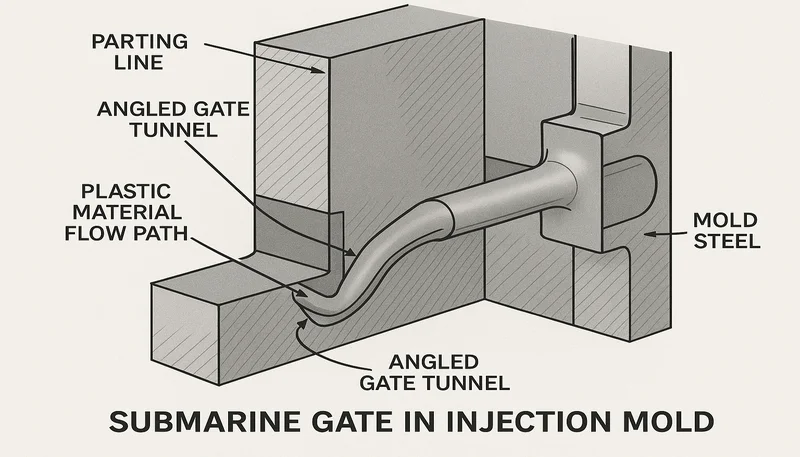
- Entradas submarinas e túneis degradam-se automaticamente na ejectação, eliminando cortes secundários em escala.
- Os sistemas de canais quentes com válvula deixam vestígios de porta de apenas 0,1–0,3 mm — essencialmente invisíveis nas peças acabadas.
- Colocar sempre a entrada na secção de parede mais grossa e fluir para secções mais finas para minimizar marcas de retração.
- Na nossa fábrica, a simulação de fluxo do molde antes da finalização da porta reduz as falhas no primeiro artigo em mais de 40%.
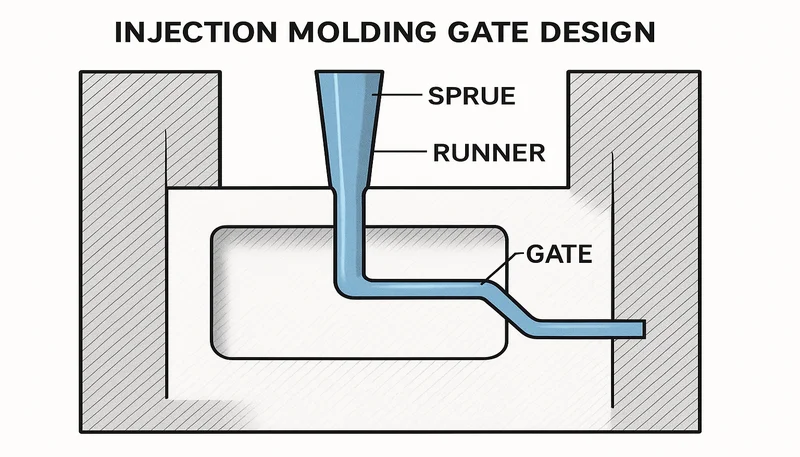
O que é o Design da Porta de Injeção e Porque é Importante?
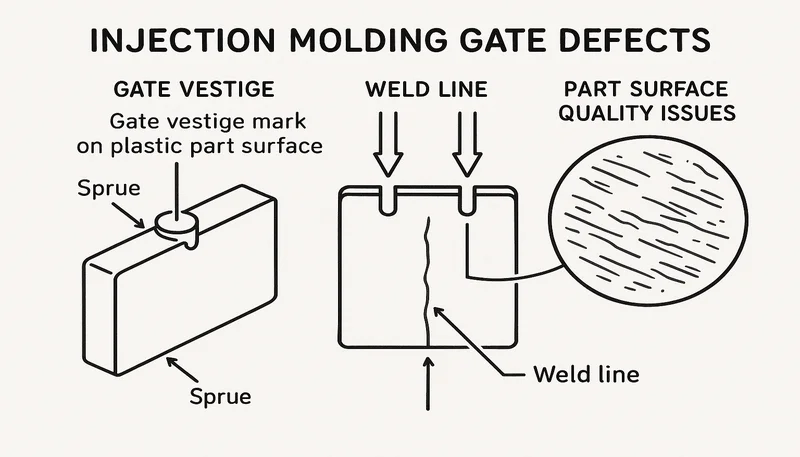
Moldagem por injeção gate design1 é a disciplina de engenharia de especificar o ponto de entrada — geometria, tamanho e posição — através do qual o plástico fundido transita do sistema de canais para a cavidade do molde. Uma porta bem projetada controla a pressão de enchimento (tipicamente 50–150 MPa na porta), a densidade de compactação e a sequência de solidificação. Errar aqui tem como consequências o jateamento, weld line3s, deformação, marcas de retração e ciclos de retrabalho custosos que podem desviar o lançamento de um produto.
A porta é o ponto mais estreito e de maior cisalhamento em todo o percurso de fluxo. As taxas de cisalhamento numa porta de borda padrão atingem tipicamente 10.000–100.000 s⁻¹, comparadas com 1.000–10.000 s⁻¹ no canal. Este cisalhamento aquece localmente o material fundido — útil para materiais semicristalinos que precisam de uma redução de viscosidade, mas destrutivo para resinas sensíveis ao calor, como PVC ou POM, se a porta for demasiado pequena. Cada decisão sobre a porta é um compromisso entre fluxo, estética, integridade estrutural e tempo de ciclo.
| Variável da Porta | Efeito na Peça | Risco se Incorreto |
|---|---|---|
| Gate location | Posição da linha de solda, área de retração | Marcas de retração, linhas de solda estruturais |
| Gate type | Tamanho do vestígio, custo de remoção da porta | Rejeições cosméticas, custo de corte |
| Tamanho da porta | Taxa de cisalhamento, pressão de enchimento, compactação | Jetting, blush, sobre-compactação |
| Longitude do terreno da entrada | Redução de pressão, erosão | Listras, erosão da porta ao longo do tempo |
| Número de portas | Equilíbrio de enchimento, número de linhas de solda | Empenamento, múltiplas marcas de vestígio |
“A colocação da entrada é a decisão mais impactante da ferramenta após a geometria da peça.”Verdadeiro
A localização da entrada controla a distribuição da pressão de enchimento, a posição da linha de solda, a formação de marcas de retração e a qualidade da superfície. Os dados da nossa fábrica mostram que mais de 65% dos defeitos do primeiro artigo em novos moldes de injecção são atribuídos a uma localização suboptimal da entrada — tornando a revisão da entrada um passo obrigatório no nosso processo de design para fabricação antes de qualquer corte de aço.
“Qualquer localização da entrada que permita que a cavidade se encha completamente é aceitável.”Falso
O enchimento completo é necessário, mas não suficiente para um bom design de entrada. Uma entrada na linha de separação colocada para conveniência da ferramenta pode criar linhas de solda em zonas estruturais, marcas de retração em secções grossas e manchas na superfície em faces cosméticas — tudo isso passa uma verificação de enchimento, mas falha na inspeção funcional e estética. A localização da entrada deve ser projetada baseada na geometria da peça e na reologia da resina, não padronizada para a posição de conveniência da ferramenta.
A nossa equipa de engenharia revisa a configuração da entrada em cada nova ferramenta antes do corte do aço. Tratamos a colocação da entrada como uma variável de design de primeira classe junto com ângulo de inclinação e linha de separação. Esta abordagem reduz as falhas relacionadas com a porta no primeiro artigo em mais de 40%. Relocalizar uma porta em CAD custa menos de €200; relocalizá-la após o corte do aço custa €800–€2.500 — um argumento poderoso para antecipar a revisão da porta no processo de design antes de qualquer maquinagem começar.
| Defeito | Correção de Engenharia da Porta | Correção apenas de Processo (Ineficaz) |
|---|---|---|
| Jato | Porta mais larga ou reposicionamento | Reduzir velocidade de injecção |
| Blush da entrada | Porta mais larga, zona de porta mais longa | Temperatura de fusão mais baixa |
| reduza o desperdício de corredores mantendo o plástico fundido, mas eles adicionam $5.000–$15.000 ao custo do molde. Saiba mais no nosso guia de moldes de corredor quente. | Porta de entrada na secção mais espessa | Aumentar a pressão de compactação |
| Weld line | Relocalizar ou adicionar porta de injeção | Aumentar a temperatura de fusão |
| Página de guerra | Centralizar ou adicionar segundo ponto de injeção | Extend cooling time |
Compreender a função da porta começa com a física do fluxo. O plástico fundido entra na porta a alta velocidade (1–5 m/s) e desacelera à medida que se espalha na cavidade. A geometria da porta controla a rapidez com que esta desaceleração ocorre. Uma porta demasiado estreita mantém uma velocidade elevada demasiado longe na cavidade, causando jato. Uma porta demasiado larga atrasa o congelamento, prolongando o tempo de ciclo e permitindo o fluxo contínuo após a libertação da pressão de enchimento, levando a rebarbas. Otimizar o tamanho da porta significa encontrar a janela entre estes dois modos de falha para a combinação específica de resina e secção da parede.
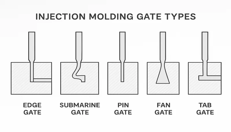
Quais são os Principais Tipos de Portas de Moldagem por Injeção?
A seleção do tipo de porta depende da geometria da peça, da resina, do volume de produção e de se a remoção da porta é manual ou automática. Os seis tipos de porta mais comuns resolvem cada um uma combinação diferente destas restrições, com o custo e a qualidade cosmética como os principais diferenciadores.
| Tipo de porta | Desgatação Automática | Best Application | Comprimento Típico do Terreno |
|---|---|---|---|
| Edge (Side) Gate | Não | Peças planas/de paredes finas, prototipagem | 0.5–1.5 mm |
| Submarine (Tunnel) Gate | Yes | Peças cosméticas de alto volume | 1.0–3.0 mm |
| Porta de Pino (Porta de Ponto Exato) | Sim (3 placas) | Pequenas peças de precisão | 0.5–1.0 mm |
| Fan Gate | Não | Painéis planos largos, lentes | 0.5–1.0 mm |
| Tab Gate | Não | Resinas frágeis, peças sensíveis a tensões | 1.0–2.0 mm |
| Porta de Diafragma (Disco) | Não | Peças cilíndricas/tubulares | 0,3–0,8 mm |
O ponto de injeção lateral é o cavalo de batalha da prototipagem e de séries de baixo volume: fácil de maquinar, fácil de modificar e deixa um vestígio visível que pode ser aparado rente. Para superfícies cosméticas, o ponto de injeção submarino tunela sob a linha de separação e corta limpo na ejeção. Os pontos de injeção por pino em moldes de três placas permitem a injeção central em peças redondas com separação automática dos canais, embora o desperdício de canais frios aumente o custo de material por tiro em 8–15%. Os pontos de injeção diafragma envolvem todo o perímetro de uma peça cilíndrica, eliminando linhas de solda para componentes tubulares.
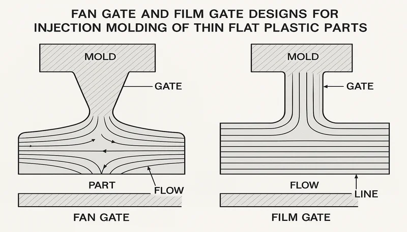
As portas em leque espalham o material fundido numa frente larga — ideal para lentes de policarbonato ou painéis de acrílico onde a birrefringência e a tensão residual devem ser minimizadas. As portas com aba adicionam um amortecedor sacrificial entre a porta e a peça, crucial para nylons com fibra de vidro, onde a concentração de tensão induzida pela porta racharia a peça em serviço. Escolher entre os tipos de porta é, em última análise, um compromisso entre qualidade cosmética, conveniência de corte, complexidade da ferramenta e compatibilidade do material.
“Os sistemas de distribuidor quente eliminam o desperdício do distribuidor e reduzem o custo do material por peça para produção de alto volume.”Verdadeiro
Os sistemas de canais frios geram desperdício de canais em cada tiro — um canal frio de 20 gramas numa ferramenta de 16 cavidades com ciclos de 30 segundos produz 9,6 kg de desperdício por hora. O investimento em canais quentes de $8.000–$25.000 recupera-se em 3–6 meses para volumes acima de 50.000 peças por ano apenas através da poupança de material, ao mesmo tempo que melhora a estética do ponto de injeção.
“O retalho da porta de injeção de sistemas de canal frio pode ser usado sem qualquer limitação na proporção da mistura.”Falso
O retalho do distribuidor frio é tipicamente misturado a 10–20% com resina virgem para aplicações não críticas. As resinas de engenharia (PC, PA66) perdem 5–15% das suas propriedades mecânicas por ciclo de retalho devido à redução do peso molecular e ao histórico térmico. Para aplicações críticas de cor ou estruturais, o uso de retalho é limitado ou totalmente proibido, exigindo um design de porta mais rigoroso e rastreamento do retalho.
Os tipos de corte automático (submarino, porta de pino, canal quente com válvula) eliminam a mão de obra de corte manual. Numa ferramenta de 24 cavidades com ciclos de 18 segundos, o corte manual da porta de injeção adiciona 0,8–1,5 segundos por peça — equivalente a 0,03–0,06 € por peça a taxas típicas de mão de obra de moldagem. Para um programa anual de 2 milhões de peças, isso representa 60.000–120.000 € em mão de obra de corte que as portas de corte automático eliminam. A nossa recomendação padrão: use portas submarinas para qualquer produção superior a 100.000 peças, quando a geometria da peça permitir a geometria do túnel angular e o tipo de resina permitir um corte limpo.
| Tipo de porta | Método de Degating | Tamanho do Vestígio | Melhor Volume |
|---|---|---|---|
| Submarino (túnel) | Corte automático na ejeção | 0,3–0,8 mm | > 100 mil peças |
| Pin gate (3-plate) | Separação da placa de canais | 0,2–0,5 mm | > 50 mil peças |
| Distribuidor quente com porta de válvula | Fecho por pino mecânico | 0.1–0.3 mm | > 50 mil peças |
| Porta de borda (distribuidor frio) | Aparagem manual necessária | 0,5–2,0 mm após aparar | < 100 mil peças |
| Porta de leque (distribuidor frio) | Aparagem manual necessária | 1,0–3,0 mm após o corte | Baixo volume / peças planas |
O tipo de porta também afeta a qualidade do retalho e a eficiência do material. As portas de borda de canal frio produzem um canal cortado, retalhado a 10–20% com resina virgem. As portas submarinas deixam um pequeno resíduo cónico no canal que alimenta limpo o sistema de retalho sem corte manual. Os sistemas de canal quente eliminam completamente o retalho — uma vantagem significativa para resinas de engenharia, onde o retalho degrada as propriedades mecânicas em 5–15% por ciclo de processamento, e para aplicações críticas de cor, onde o retalho introduz variação de cor entre lotes de produção.
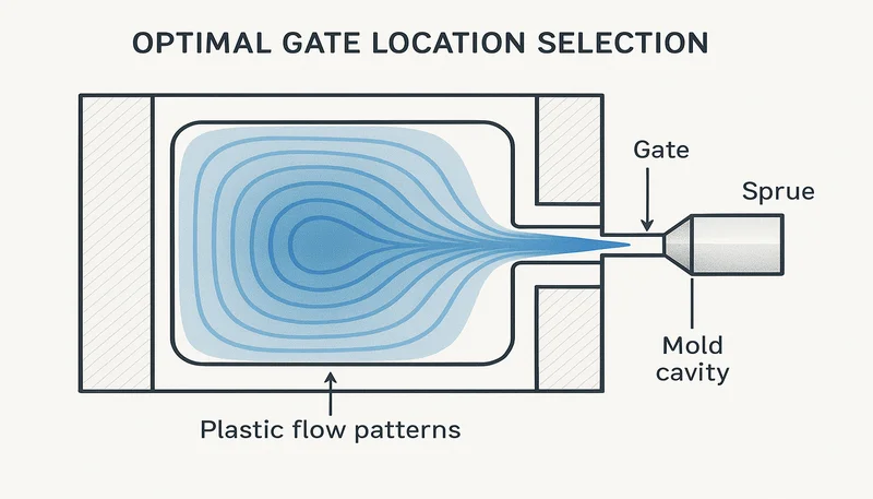
Como Deve Selecionar a Localização Ótima da Porta?
A localização ideal do orifício segue quatro regras de engenharia: orifício na secção mais espessa, evitar injetar sobre superfícies A visíveis, posicionar linhas de solda longe de concentrações de tensão e equilibrar o tempo de enchimento em todas as cavidades num molde multi-cavidade. Apenas a regra de equilíbrio de enchimento pode exigir que o orifício se desloque 15–25 mm da posição geometricamente ideal na peça para manter o enchimento equilibrado em todas as cavidades.
A entrada na parede mais espessa (ex.: 3,5 mm vs. uma nervura adjacente de 1,2 mm) permite que a pressão de enchimento mantenha a secção espessa enquanto as paredes finas solidificam primeiro. Se a entrada for numa secção fina, a secção espessa solidifica com pressão de enchimento insuficiente e afunda. Este é o erro de localização de entrada mais comum que vemos em peças transferidas de outros fornecedores — a entrada está na linha de separação por conveniência do molde, não no boss espesso onde a marca de afundamento aparece após a inspeção do primeiro artigo.
Para moldes multi-cavidade, sistemas de distribuição equilibrados (layout em H ou geometricamente equilibrado) igualam a queda de pressão em cada cavidade. No entanto, não conseguem compensar posições assimétricas do orifício dentro de cada cavidade. Usamos análise do fluxo do molde simular o equilíbrio de enchimento antes de definir a localização da entrada no aço — detetando desequilíbrios que o melhor desenho de distribuidor não consegue corrigir sozinho.
| Rule | Justificação | Consequência da Violação |
|---|---|---|
| Orifício na secção de parede mais espessa | A pressão de empacotamento atinge áreas espessas antes do congelamento | Marcas de afundamento em elementos espessos |
| Evitar superfícies cosméticas Classe-A | O vestígio da entrada é visível na peça acabada | Rejeições cosméticas, corte secundário |
| Linhas de solda longe de zonas de tensão | Linhas de solda reduzem a resistência em 10–30% | Falha estrutural na linha de solda |
| Equilibrar o tempo de enchimento entre as cavidades | Garante enchimento igual em todas as cavidades | Contração diferencial, variação dimensional |
| Escoamento de secções espessas para finas | Secções finas solidificam por último, sem afundamento | Injeções curtas em características finas |
Para peças com furos passantes ou bossas altas, cada obstáculo divide a frente de fluxo e cria uma linha de solda no lado a jusante. Ao colocar a entrada oposta ao furo crítico, a linha de solda é empurrada para além do furo para uma região menos tensionada. Os nossos engenheiros de ferramental mapeiam as posições esperadas das linhas de solda em cada revisão de projeto antes do molde chegar à oficina, prevenindo o cenário demasiado comum de descobrir uma linha de solda a atravessar um encaixe de pressão apenas após os testes do primeiro artigo e o envio do molde da fábrica.
A relação entre o comprimento de fluxo mais longo e o mais próximo é uma métrica útil de viabilidade para orifício único: se esta relação exceder 1,8:1 para uma peça, o empacotamento diferencial torna-se difícil de gerir com uma única localização de orifício. Além desta relação, é necessário um segundo orifício ou um redesenho do layout do canal de distribuição. As nossas diretrizes de projeto exigem uma análise de fluxo sempre que esta relação exceder 1,5:1 para confirmar que a adequação da pressão de empacotamento é mantida em todas as espessuras de parede e alturas de características antes de aprovar a localização do orifício para ferramentas de produção.
Quais são as Regras para Dimensionar uma Entrada de Moldagem por Injecção?
O dimensionamento da entrada segue uma regra de duas restrições: a entrada deve ser grande o suficiente para permitir o enchimento completo antes do congelamento, e pequena o suficiente para cortar limpo na ejeção para tipos de auto-remoção. Para a maioria das resinas amorfas (ABS, PC, PS), a espessura da entrada é definida em 50–80% da espessura da parede na zona da entrada. As resinas semicristalinas (PA66, POM, PP) toleram entradas ligeiramente menores — 40–60% — porque a sua transição de congelamento abrupta ajuda na vedação e na remoção limpa sem um vestígio irregular.
| Resin Type | Espessura do Orifício (1/3 da Parede) | Diâmetro da Ponta Quente | Comprimento da Terra |
|---|---|---|---|
| Amorfa (ABS, PS) | 50–80% | 1.0–2.0 mm | 0.5–1.0 mm |
| Amorfo (PC, PMMA) | 60–80% | 1.5–2.5 mm | 0.5–1.0 mm |
| Semicristalino (PP, PE) | 40–60% | 1,2–2,0 mm | 0,5–0,8 mm |
| Semicristalino (PA66, POM) | 40–60% | 0,8–1,5 mm | 0,3–0,7 mm |
| Elastómeros (TPU, TPE) | 70–100% | 1.5–2.5 mm | 0.5–1.0 mm |
| Com fibra de vidro (30% GF) | +40–60% vs. não preenchida | 2.0–3.0 mm | 0.5–1.0 mm |
O comprimento da zona da porta é frequentemente negligenciado. Uma zona demasiado longa (>1,5 mm para portas pequenas) aumenta a queda de pressão e atrasa o enchimento; demasiado curta (<0,3 mm) provoca erosão da porta e estrias cosméticas. A prática padrão é uma zona de 0,5–1,0 mm para portas com espessura inferior a 2 mm. Para portas de ponta quente em sistemas de canais quentes, o diâmetro do orifício é tipicamente de 0,8–2,5 mm — nylon a 0,8–1,2 mm, polipropileno a 1,2–2,0 mm e PC de alta viscosidade a 1,5–2,5 mm.
Um orifício de injeção subdimensionado cria elevado cisalhamento e degrada resinas sensíveis ao corte. Um orifício de injeção sobredimensionado deixa um grande vestígio, requer corte secundário e, em projetos de auto-remoção, pode não cortar limpo na ejeção. Para resinas sensíveis ao cisalhamento — PVC, acetal (POM), formulações retardantes de chama — a taxa máxima de cisalhamento no orifício deve ser explicitamente especificada: PVC rígido abaixo de 20.000 s⁻¹ para evitar geração de HCl, acetal abaixo de 50.000 s⁻¹ para evitar emissão de formaldeído. Os nossos projetistas de moldes calculam a área do orifício usando: Área do Orifício (mm²) = Taxa de Fluxo (cm³/s) ÷ Taxa de Cisalhamento Máxima Permitida (s⁻¹).
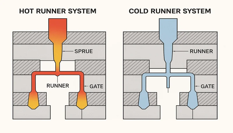
Como Difere o Design da Porta para Sistemas de Canal Quente vs. Canal Frio?
O projeto de entrada de canal quente elimina completamente o canal frio: a massa fundida permanece no estado fundido dentro de coletores aquecidos e entra na cavidade através de uma ponta quente com entrada térmica ou com válvula. O vestígio da entrada é tipicamente 0,1–0,3 mm — quase invisível — comparado com 0,5–2 mm para entradas de borda de canal frio. Esta diferença é enormemente importante para peças automotivas Classe A e de eletrónica de consumo, onde marcas de entrada em superfícies visíveis não são aceitáveis para os clientes finais.
Os distribuidores quentes com entrada térmica dependem de uma solidificação controlada no orifício da ponta. São mais simples e baratos (sem pino de válvula), mas deixam uma pequena depressão e são propensos a formação de fios se a temperatura da ponta variar mais de ±3°C. Os sistemas com válvula usam um pino acionado para fechar mecanicamente o orifício no final do enchimento, dando uma marca de entrada mais limpa e melhor repetibilidade do processo ao longo da produção.
Os sistemas de canal frio custam menos para construir, mas geram desperdício de canal em cada injeção. Para um molde de 16 cavidades com ciclos de 30 segundos, um canal frio de 20 gramas adiciona 9,6 kg de desperdício por hora. O investimento em canal quente (tipicamente um custo adicional de ferramental de €8.000–€25.000) é recuperado em 3–6 meses em volumes médios a altos. O conceção de moldes de injeção deve considerar a expansão térmica do coletor do canal quente — tipicamente 0,3–0,6 mm por 100 mm à temperatura de operação — para evitar rebarbas ou interferência da entrada na linha de separação.
“A entrada sequencial com válvula pode eliminar linhas de solda em painéis moldados por injeção grandes.”Verdadeiro
A abertura sequencial de válvulas (SVG) abre pinos de entrada individuais em sequência, guiando a frente de fluxo através de uma peça grande e impedindo que duas frentes de fluxo se encontrem em locais de alta tensão. Esta técnica elimina linhas de solda em painéis de instrumentos automotivos e interiores de portas traseiras, permitindo decisões de colocação de entrada baseadas puramente em requisitos estruturais, em vez de evitar linhas de solda cosméticas.
“Os moldes com distribuidor quente não requerem gestão térmica adicional em comparação com os moldes com distribuidor frio.”Falso
Os moldes de canal quente requerem controle de temperatura preciso zona por zona — as zonas do coletor geralmente operam a 200–330°C, enquanto o aço do molde circundante opera a 20–80°C. O gradiente térmico cria uma expansão diferencial que deve ser projetada na montagem do coletor, no alinhamento da ponta da porta e nas folgas da linha de separação. Sem esse gerenciamento térmico, ocorrem interferência na porta, rebarbas e tamanho inconsistente do vestígio.
A porta de válvula sequencial (SVG) é uma técnica de canal quente onde pinos de válvula individuais abrem sequencialmente ao longo de uma peça grande, guiando a frente de fluxo e eliminando linhas de solda. O SVG requer temporização precisa da válvula (tipicamente ±0,1 segundos por porta) e simulação de fluxo no molde para mapear a sequência ótima de abertura das portas. Em aplicações de painéis automotivos (painéis de instrumentos, painéis internos de porta-malas), o SVG reduz o número de linhas de solda de 3–5 para zero e permite total liberdade no posicionamento das portas para o desempenho estrutural da peça, em vez de um compromisso estético.
“Os sistemas de canais quentes com válvula produzem vestígios de canal de entrada mais pequenos do que os canais de borda de canais frios.”Verdadeiro
As pontas quentes com válvula fecham mecanicamente com um pino, produzindo uma marca de canal de 0,1–0,3 mm — em comparação com 0,5–2,0 mm para um canal de borda de distribuidor frio aparado. Isto torna-as a escolha preferida para superfícies cosméticas Classe A em aplicações automóveis e de eletrónica de consumo, onde marcas de canal em superfícies visíveis são esteticamente inaceitáveis.
“Uma porta maior sempre melhora o enchimento e elimina peças incompletas.”Falso
O tamanho do canal deve ser equilibrado com o tempo de congelamento, o tamanho do vestígio e a geração de calor por corte. Canais demasiado grandes prolongam o congelamento, causando rebarbas ou sobrecompactação em secções finas a jusante. Para projetos de auto-desgatação, canais demasiado grandes não cortam limpos na ejeção. A abordagem correta é dimensionar o canal para 50–80% da espessura da parede local e, em seguida, verificar com simulação de fluxo de moldação antes de usinar o aço.
Que Defeitos são Causados por um Mau Design da Porta?
Um projeto de porta deficiente produz seis categorias principais de defeitos: jato, linhas de solda em zonas estruturais, marcas de afundamento, mancha na porta, vestígio excessivo e empenamento. Compreender a causa raiz de cada defeito é o primeiro passo para a modificação correta da porta — tentar corrigir defeitos da porta com alterações nos parâmetros do processo (velocidade, temperatura, pressão) geralmente falha, a menos que o problema geométrico subjacente da porta seja resolvido primeiro.
O jato ocorre quando um fluxo fino de material fundido dispara através da cavidade antes de se espalhar, criando uma marca superficial semelhante a uma cobra. A causa é um canal de entrada demasiado pequeno em relação à secção transversal da cavidade. A solução é aumentar a largura do canal de entrada (não a espessura) para que o material fundido se espalhe imediatamente, ou reposicionar o canal de entrada para que incida numa parede oposta a 10–15 mm. O blush no canal de entrada — um anel nebuloso à volta do canal — resulta de uma elevada tensão de corte na zona de aterragem do canal; alargar o canal e aumentar o comprimento da aterragem de 0,3 para 0,8 mm reduz a taxa de corte em 30–50% e elimina o blush.
“Reposicionar a porta é mais eficaz do que aumentar a velocidade de injeção para eliminar o jato.”Verdadeiro
O jato é um problema de geometria da porta — o fluxo do fundido deve se espalhar imediatamente ao entrar na cavidade. Aumentar a velocidade de injeção piora o jato ao elevar a velocidade do fluxo. A correção correta é alargar a porta ou movê-la para que o fluxo atinja uma parede oposta, criando um espalhamento imediato e eliminando o padrão de fluxo serpentino na superfície da peça.
“A mancha na porta pode sempre ser corrigida reduzindo a temperatura do fundido.”Falso
A mancha na porta é causada por alta tensão de cisalhamento no comprimento da porta, não primariamente pela temperatura do fundido. Reduzir a temperatura aumenta a viscosidade e, portanto, a tensão de cisalhamento, piorando a mancha. A correção correta é aumentar a largura da porta e o comprimento do canal para reduzir a taxa de cisalhamento. A temperatura do fundido é uma variável secundária; alterações na geometria da porta são a solução primária e permanente para a eliminação da mancha na porta.
Marcas de encolhimento perto do canal indicam que o canal congelou antes de a pressão de compactação adequada atingir a secção espessa. Aumentar a espessura do canal estende a janela de compactação e resolve o encolhimento. Linhas de soldadura em zonas estruturais exigem a relocalização do canal para que as frentes de fluxo se encontrem em áreas de baixa tensão, ou a adição de um segundo canal para eliminar a linha de solda. A deformação por canal descentrado cria compactação diferencial; centralizar o canal ou usar dois canais colocados simetricamente corrige isto. Rebarbas no canal indicam um canal demasiado grande; reduzir a espessura do canal em 0,2–0,3 mm mantendo a largura é a primeira ação corretiva.
Injeções curtas que não podem ser resolvidas por alterações de parâmetros do processo (maior velocidade ou pressão de injeção) normalmente exigem mover o canal de injeção para mais perto da característica problemática de parede fina. Um reposicionamento do canal de 20–30 mm pode resolver a hesitação em características de parede fina longe da localização original do canal. O nosso protocolo de resolução de defeitos começa com uma revisão da geometria do canal antes de quaisquer alterações de parâmetros do processo — uma disciplina que reduz o tempo desde a identificação do defeito até à resolução da causa principal em média dois dias, em comparação com a resolução de problemas que prioriza o processo.
Como Projetar Portas para Materiais Específicos?
A reologia do material dita a geometria do canal de injeção. Resinas de alta viscosidade como policarbonato exigem canais maiores (1,5–2,5 mm para pontas quentes, 2,0–4,0 mm de largura para canais de borda) para evitar queda de pressão excessiva e degradação na zona do canal. O nylon 6/6 ou POM de baixa viscosidade pode usar canais menores (0,8–1,5 mm) porque a sua baixa viscosidade do fundido à temperatura de processamento (220–280°C) permite um enchimento adequado através de orifícios menores sem queda de pressão excessiva no canal.
As resinas sensíveis ao corte apresentam um desafio específico que o dimensionamento do canal controla diretamente. Para PVC rígido, a taxa de corte no canal deve permanecer abaixo de 20.000 s⁻¹ para evitar degradação térmica e geração de gás HCl. O acetal (POM) requer corte abaixo de 50.000 s⁻¹ para evitar a libertação de formaldeído, que cria vazios, odor pungente e corrosão da cavidade do molde. Para estas resinas, especificamos uma taxa de corte máxima permitida no canal na especificação de projeto do molde, e análise do fluxo do molde2 deve confirmar a conformidade do cisalhamento antes que as dimensões da porta sejam aprovadas para a ferramenta de produção.
| Resin | Taxa de Corte Máxima no Canal de Entrada | Risco se excedido | Resposta do Projeto da Porta |
|---|---|---|---|
| PVC rígido | < 20.000 s⁻¹ | Gás HCl, corrosão da cavidade | Canal de entrada em leque largo, aterragem de 0,3 mm |
| Acetal (POM) | < 50.000 s⁻¹ | Emissão de formaldeído, vazios | Canal de entrada maior, velocidade de injeção mais baixa |
| Graus FR | < 30.000 s⁻¹ | Decomposição de aditivos, corrosão | Canal de entrada largo, aterragem curta 0,3–0,5 mm |
| Estabilizado contra UV | < 40.000 s⁻¹ | Degradação de aditivos, estrias | Canal mais largo, verificar com simulação |
| LCP | < 100.000 s⁻¹ | Cristalização induzida por corte | Alargar o canal 10–15%, verificar Cpk |
O índice de fluidez (MFI) fornece uma referência inicial útil para o dimensionamento do canal de injeção. Resinas com MFI 20 g/10min (baixa viscosidade: homopolímero de PP, PA6) podem usar dimensões de canal no extremo inferior. As resinas cristalinas exigem consideração adicional para a cristalização induzida por corte na ponta do canal: para PP e LCP de alta cristalinidade, alargar o canal em 10–15% elimina a variação de peso entre injeções e atende consistentemente aos requisitos automóveis de Cpk > 1,67.
Os dados de MFI dos fornecedores de resina devem ser aplicados com cuidado. O MFI é medido a uma única temperatura e baixa taxa de cisalhamento sob uma carga padrão, mas em uma porta de molde de injeção real, a taxa de cisalhamento pode ser 100–1000× maior do que as condições de teste do MFI. Uma resina que parece processável pelo seu valor de MFI ainda pode exibir aquecimento por cisalhamento excessivo, degradação ou efeitos de orientação em uma porta pequena devido às taxas de cisalhamento extremamente altas presentes durante a fase de enchimento. Sempre confirmamos com um estudo de peça incompleta e simulação de taxa de cisalhamento antes de finalizar as dimensões da porta de produção para qualquer nova resina.
Os graus com carga de vidro (30–50% de carga de fibra) são fortemente afetados pela orientação por corte no canal. Um canal estreito cria um alinhamento radial das fibras que reduz a resistência à tração transversal em 20–40% vs. resina base para componentes sob carga estrutural. Para peças com carga de vidro, a largura do canal deve ser ≥4 mm (canal em leque ou canal de borda largo) para moderar a orientação das fibras — ou usar um canal de aba para amortecer a zona de concentração de tensões e separar a região do canal de alto corte da geometria da peça sujeita a carga, onde a resistência total à tração transversal é exigida pela especificação de desempenho estrutural.
“A orientação das fibras de vidro no canal de entrada reduz a resistência à tração transversal em 20–40%.”Verdadeiro
Num canal de injeção estreito, as elevadas taxas de corte alinham as fibras de vidro radialmente a partir do centro do canal. Estas fibras suportam a carga eficientemente na direção do fluxo, mas fornecem reforço mínimo transversalmente ao fluxo. Para peças estruturais com cargas perpendiculares à direção de enchimento, este efeito de orientação reduz a resistência à tração em 20–40% em comparação com o valor isotrópico da resina base. Canais de injeção em leque largos moderam este efeito, distribuindo a orientação das fibras de forma mais uniforme.
“Os graus retardantes de chama podem ser processados através das mesmas dimensões de canal de injeção que os graus padrão não preenchidos da mesma resina base.”Falso
Os aditivos FR são sensíveis ao cisalhamento em níveis muito abaixo do limiar de degradação da resina base. Mesmo dentro da janela de processamento normal da resina base, taxas de cisalhamento na entrada acima de 30 000 s⁻¹ podem decompor os aditivos FR, libertando gases corrosivos que atacam o aço do molde e reduzem a retardância de chama abaixo dos níveis de conformidade UL-94. Os graus FR requerem entradas mais largas com comprimentos de terra mais curtos, independentemente da especificação de viscosidade da resina base.
Os elastómeros (TPU, TPE) requerem entradas ≥2 mm de largura porque o seu alto alongamento os torna propensos a rasgar em pequenos vestígios durante a ejeção. Para sobremoldagem Nas aplicações, a localização da entrada deve evitar a injeção diretamente sobre o inserto do substrato, uma vez que a frente de fluxo de alta velocidade pode deslocar ou danificar a superfície do substrato durante a fase inicial de enchimento da cavidade e antes de o material de sobre-moldagem encapsular o substrato. Os compostos retardantes de chama são sensíveis ao cisalhamento; a decomposição do aditivo FR a elevadas taxas de cisalhamento liberta gases corrosivos que danificam o aço da cavidade do molde, pelo que são especificadas entradas mais largas com terras mais curtas (0,3–0,5 mm) para todos os graus FR no nosso padrão de desenho de entrada de fábrica.
Os compostos de fibra de carbono (30% CF) podem pontear e bloquear entradas subdimensionadas no arranque, criando inconsistência de enchimento entre peças. Aumentamos as dimensões da entrada em 40–60% para materiais CF em relação à especificação da resina base não preenchida, e orientamos a direção do fluxo da entrada paralelamente ao eixo de carga principal da peça para alinhar favoravelmente as fibras para o desempenho de suporte de carga. Estas duas medidas reduzem a taxa de defeitos da primeira peça de CF de 12–15% para menos de 3% na nossa experiência de lançamento de novo molde. As resinas cristalinas (LCP, PP de alta cristalinidade) requerem vigilância contra a cristalização induzida por cisalhamento na ponta da entrada; alargar a entrada em 10–15% elimina a variação de peso da peça e cumpre consistentemente os requisitos de capacidade de processo automóvel Cpk > 1,67 através de diferentes plataformas de máquina e variações de lote de resina.
Quais São as Melhores Práticas para Validar o Design da Porta Antes da Produção?
A validação do porta segue um processo em três etapas: simulação, subenchimentos T1 e inspeção dimensional do primeiro artigo. Omitir qualquer etapa aumenta o risco de descobrir um problema no porta após centenas de tiragens de produção — quando os custos de correção são 5 a 10 vezes superiores aos da fase de projeto. Na nossa fábrica, este processo em três etapas é obrigatório para cada ferramenta nova, independentemente da complexidade da peça ou do volume de produção.
A simulação de fluxo de moldação prevê o tempo de enchimento, localizações das linhas de solda, posições de aprisionamento de ar e distribuição de pressão no ponto de injeção. Uma simulação que mostre pressão de enchimento superior a 140 MPa no ponto de injeção é um aviso precoce: o ponto pode ser demasiado pequeno, o canal distribuidor demasiado restritivo, ou a secção de parede demasiado fina para a resina escolhida. A simulação também revela se o ponto de injeção congela antes de ser transmitida pressão de compactação adequada — uma verificação crítica para peças com bossos ou nervuras espessos que devem ser mantidos sob pressão de compactação para evitar a formação de marcas de afundamento.
| Estágio | Key Check | Pass Criterion |
|---|---|---|
| Simulação de Fluxo de Moldação | Pressão de enchimento no porta | < 140 MPa |
| Simulação de Fluxo de Moldação | Weld line location | Afastado de zonas estruturais |
| Simulação de Fluxo de Moldação | Momento de congelamento do ponto de injeção | Após o patamar de pressão de compactação |
| T1 Peças Incompletas | Frente de fluxo a 70% de enchimento | Sem hesitação em características finas |
| T1 Peças Incompletas | Estudo de solidificação do porta | Patamar de peso confirmado |
| Inspeção do Primeiro Artigo | Altura do vestígio do ponto de injeção | ≤ 0,5 mm acima da superfície |
| Inspeção do Primeiro Artigo | Profundidade do afundamento próximo ao ponto de injeção | ≤ 0,1 mm (superfície Classe-A) |
Os subenchimentos T1 (enchimento da cavidade a 70%, 85%, 95%) revelam a progressão real da frente de fluxo e identificam zonas de hesitação onde a frente de fluxo para em nervuras finas ou características afastadas do porta. Se ocorrer hesitação, o porta pode precisar de ser deslocado ou o diâmetro do canal pode precisar de aumentar. A inspeção dimensional final inclui a altura do vestígio do porta (alvo ≤0,5 mm acima da superfície da peça) e a profundidade de encolhimento perto da zona do porta (alvo ≤0,1 mm para superfícies Classe-A).
Na nossa fábrica, todas as ferramentas novas são submetidas a um estudo de solidificação do porta durante o T1: variamos o tempo de pressurização de 2 a 12 segundos em incrementos de 2 segundos e pesamos cada tiragem. O tempo de pressurização em que o peso da peça estabiliza identifica o tempo de selagem do porta — para uma espessura de parede típica de 3 mm, o tempo de selagem do porta é de 4 a 8 segundos, dependendo do tamanho do porta e da resina. Estes dados são bloqueados na folha de processo de produção antes do início da produção em volume, garantindo que a geometria validada do porta é mantida durante todo o ciclo de vida do produto e não é alterada inadvertidamente durante a otimização subsequente do processo.
About ZetarMold — Your Injection Molding Manufacturer
Looking for a reliable fabricante de moldagem por injeção? ZetarMold delivers 100+ precision molds monthly with expertise in 400+ materials. Request a free quote →
Perguntas Frequentes Sobre o Design de Portas de Moldagem por Injeção
Qual é o tamanho padrão do portão para moldagem por injeção?
Não existe um tamanho padrão único para o ponto de injeção — depende da espessura da parede, da viscosidade da resina e do tipo de ponto. A regra mais comummente aplicada é definir a espessura do ponto de injeção entre 50% e 80% da espessura nominal da parede na zona de entrada. Para uma parede de 2,5 mm, isto resulta numa espessura de ponto entre 1,25 mm e 2,0 mm. A largura do ponto é tipicamente 1,5 a 2 vezes a sua espessura para um ponto lateral. Os orifícios das pontas de distribuidor quente variam de 0,8 mm para nylon de baixa viscosidade a 2,5 mm para policarbonato de alta viscosidade. Verifique sempre o tamanho final do ponto através de simulação de fluxo de moldação, em vez de confiar apenas em regras práticas.
Onde deve ser colocada a porta numa parte moldada por injecção?
O ponto de injeção deve ser colocado na secção de parede mais espessa, longe das superfícies cosméticas Classe-A, e posicionado de modo que a frente de fluxo se mova das secções espessas para as finas. Esta abordagem de enchimento prioritário garante que as marcas de afundamento se formem em áreas menos visíveis e que a pressão de compactação seja adequadamente transmitida às secções espessas antes do congelamento do ponto de injeção. Para ferramentas multicavidade, a posição do ponto de injeção também deve ser escolhida para equilibrar o tempo de enchimento entre as cavidades. Pontos estruturalmente fracos, como braços de encaixe por pressão e nervuras de carga, devem ser localizados longe das linhas de solda, que se formam a jusante do ponto de injeção onde duas frentes de fluxo convergem.
Qual é a diferença entre um porta de corredor frio e um porta de corredor quente?
Um porta de distribuidor frio liga a cavidade a um sistema de canais solidificado que é ejetado com a peça e reciclado ou rejeitado. Tem um custo de construção mais baixo, mas gera desperdício de material em cada tiragem. Um porta de distribuidor quente liga-se a uma distribuição aquecida que mantém o plástico fundido entre tiragens, eliminando totalmente o desperdício dos canais. Os vestígios do porta de distribuidor quente são tipicamente de 0,1–0,3 mm para sistemas com válvula, versus 0,5–2,0 mm para portas de borda de distribuidor frio. A ferramenta de distribuidor quente acrescenta 8.000–25.000 € em custos iniciais, mas paga-se rapidamente em volumes de produção acima de 50.000 peças por ano apenas através da poupança de material.
Como elimina o vestígio de porta na moldagem por injeção?
O vestígio do porta é minimizado escolhendo um tipo de porta que se separa limpo automaticamente: portas submarinas (túnel) são cisalhadas na ejeção, portas de pino em moldes de três placas partem-se com a placa dos canais, e as pontas do distribuidor quente com válvula fecham mecanicamente, deixando apenas uma pequena covinha de 0,1–0,3 mm. Para portas de borda de distribuidor frio, o vestígio é minimizado mantendo o comprimento da zona do porta abaixo de 1,0 mm e aparando ao nível numa operação secundária. Mover o porta para uma superfície interior ou não cosmética é a forma mais fiável de tornar o vestígio invisível na peça acabada sem uma operação secundária.
O que causa linhas de solda na moldagem por injeção e como a colocação do gate ajuda?
Linhas de solda formam-se onde quer que duas frentes de fluxo separadas se encontrem e se fundam, tipicamente a jusante de portas, furos, pinos e insertos na cavidade do molde. A colocação do porta controla diretamente onde as linhas de solda aparecem: mover o porta altera o caminho do fluxo e desloca as posições da linha de solda. O objetivo é localizar as linhas de solda em áreas de baixa tensão, afastadas de encaixes por pressão, furos de montagem e superfícies visíveis. Quando um único porta não consegue evitar uma linha de solda estrutural, adiciona-se um segundo porta para fundir as frentes de fluxo antes de atingirem a característica crítica, eliminando completamente a linha de solda no local de alta tensão.
O design do portão pode afetar a deformação da peça na moldagem por injeção?
Sim — a localização e o tipo do porta de injeção afetam significativamente o empenamento porque controlam a orientação das fibras, a distribuição de tensões residuais e a retração diferencial na peça. Uma porta de injeção assimétrica numa peça simétrica cria um fluxo desequilibrado que produz tensões residuais assimétricas e deformação após a ejeção. Para painéis planos, uma porta central ou uma porta de leque ao longo da largura total produz uma retração mais uniforme do que uma única porta de borda. Os materiais com carga de vidro são particularmente sensíveis ao empenamento porque a orientação das fibras no porta cria uma zona de retração transversal reduzida. A simulação de fluxo de moldação prevê a magnitude do empenamento e orienta a relocalização do porta antes de qualquer ferramenta ser cortada.
-
design do gate: O projeto da porta refere-se à especificação técnica do ponto de entrada através do qual o plástico fundido flui do sistema de distribuição para a cavidade do molde, incluindo tipo, tamanho, localização e geometria da porta. ↩
-
mold flow analysis: Mold flow analysis is a computer simulation technique that predicts how molten plastic fills a mold cavity, identifying potential defects such as short shots, weld lines, and sink marks before tooling is cut. ↩
-
weld line: Uma linha de solda é uma costura visível ou zona estrutural fraca numa peça moldada que se forma onde duas frentes de fluxo separadas de plástico fundido se encontram e fundem, ocorrendo tipicamente a jusante de portas, furos ou obstáculos na cavidade. ↩


