 Saltar para o conteúdo

Calculando a área projetada1 é um dos primeiros e mais críticos passos em qualquer moldagem por injeção2 projeto. Se errar, corre o risco de flash3 defeito, danos na máquina ou incapacidade de encher o molde. Acertando neste cálculo, pode selecionar com confiança a prensa correta, estimar a força de fecho e produzir peças de qualidade desde o primeiro dia.
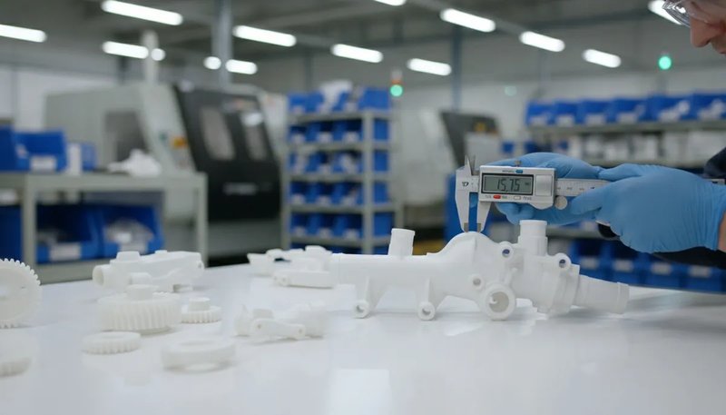
Na nossa fábrica de Xangai, operamos 47 máquinas de moldagem por injeção, desde 90T até 1850T. Cada projeto começa com a mesma pergunta: qual é a área projetada e o nosso equipamento tem força de fecho suficiente? Este guia conduz-o através do processo de cálculo com fórmulas reais, exemplos resolvidos e dicas práticas de duas décadas de experiência de produção.
- A área projetada é a silhueta 2D da sua peça ao longo da direção de fecho
- Força de Fecho = Área Projetada × Pressão na Cavidade × Fator de Segurança
- Inclua sempre as áreas do canal de alimentação e do ponto de injeção no seu cálculo
- Formas complexas podem ser decompostas em formas geométricas mais simples
- Uma margem de segurança de 10-20% previne rebarbas e injetadas curtas
O que é Área Projetada na Moldagem por Injeção?
A área projetada na moldagem por injeção é a sombra ou silhueta bidimensional da sua peça quando vista na direção de fecho do molde. Imagine segurar uma lanterna diretamente acima de um objeto — a sombra que este projeta na mesa é a sua área projetada. Esta medição, tipicamente expressa em centímetros quadrados (cm²) ou polegadas quadradas (in), determina diretamente a força de fecho necessária para manter o molde selado durante a injeção.
Para uma visão mais ampla, o nosso injection molding complete guide abrange os fundamentos do processo, o comportamento do material e as decisões de produção.
If you are comparing vendors or planning procurement, our injection molding supplier sourcing guide covers RFQ prep, qualification, and commercial risk checks.
Porque é tão importante? Quando o plástico fundido entra na cavidade do molde sob alta pressão, gera uma força para fora proporcional à área projetada. Se a força de fecho da máquina for inferior a esta força para fora, o molde abrirá ligeiramente na linha de separação, causando rebarbas — finas arestas indesejadas de plástico ao longo das bordas da sua peça. Em ambientes de produção, rebarbas significam retrabalho, sucata ou peças rejeitadas.
Na nossa fábrica em Xangai, operamos 47 máquinas de moldagem por injeção de 90T a 1850T. Cada novo projeto começa com o cálculo da área projetada para garantir que selecionamos uma prensa com capacidade de fecho adequada — este único cálculo evita tentativa e erro dispendiosa no chão de fábrica.
Como Calcular a Área Projetada Passo a Passo?
A área projetada é calculada decompondo a peça em formas geométricas básicas, medindo cada silhueta e somando os resultados. Aqui está o nosso método passo a passo.
Passo 1: Determinar a Direção de Fecho
Antes de medir qualquer coisa, identifique em que direção o molde abre e fecha. Esta é geralmente perpendicular à linha de separação. A área projetada é medida ao longo deste eixo. Para a maioria das peças padrão, esta é a direção em que as placas móveis se deslocam.
Passo 2: Dividir a Peça em Formas Geométricas Simples
Observe a peça a partir da direção de fecho. Divida o seu contorno em formas básicas — retângulos, círculos, triângulos e trapézios. Cada forma tem uma fórmula de área conhecida:
Aqui estão as fórmulas básicas de que irá precisar: Retângulo = Comprimento x Largura (ex.: 50 mm x 30 mm = 1.500 mm²); Círculo = pi x raio ao quadrado (ex.: pi x 20 ao quadrado = 1.257 mm²); Triângulo = 0,5 x Base x Altura (ex.: 0,5 x 40 x 25 = 500 mm²); Trapézio = 0,5 x (a + b) x h (ex.: 0,5 x (30 + 50) x 20 = 800 mm²).
Passo 3: Calcular Cada Forma e Somá-las
Aplique a fórmula apropriada a cada subforma e, em seguida, some todas as áreas. Para uma peça que se parece com um retângulo com uma aba semicircular, calcularia a área retangular, a área semicircular e somaria ambas.
Passo 4: Adicionar as Áreas do Canal de Alimentação e do Ponto de Injeção
Não se esqueça do sistema de canais. O plástico fundido viaja através dos canais e das entradas antes de entrar na cavidade. Estes canais também geram força para fora no molde. Inclua a área projetada dos canais no seu total. Em moldes multi-cavidade, multiplique a área de uma única cavidade pelo número de cavidades, depois some a área total dos canais.
Passo 5: Aplicar Correção do Ângulo de Saída (Se Necessário)
Para peças com ângulos de saída significativos, a área projetada pode diferir da medição da área plana. A maioria dos ângulos de saída (1-3 graus) tem um impacto negligenciável, mas para peças de grande profundidade com ângulos de saída de 5+ graus, recalcule a silhueta considerando as paredes inclinadas. Na prática, esta correção raramente excede 2-3% da área total.
Qual é a Fórmula para a Força de Fecho a partir da Área Projetada?
Assim que tiver a área projetada, a fórmula da força de fecho é a chave para selecionar a máquina certa. A equação fundamental é:
Força de Fecho (kgf) = Área Projetada (cm²) × Pressão da Cavidade (kgf/cm²)
Convertendo para toneladas (onde 1 tonelada = 1.000 kgf):
Força de fecho (Tonelagem) = [Área Projetada (cm²) × Pressão na Cavidade (kgf/cm²)] ÷ 1.000
A pressão na cavidade depende do material a ser moldado. Aqui estão os valores típicos de pressão na cavidade para materiais comuns:
| Material | Pressão na Cavidade (kgf/cm²) | Pressão na Cavidade (ton/pol²) |
|---|---|---|
| PS (Poliestireno) | 150–250 | 1.0–1.7 |
| PE (Polietileno) | 200–300 | 1.4–2.1 |
| PP (Polipropileno) | 200–350 | 1,4–2,5 |
| ABS | 300–500 | 2,1–3,5 |
| PA (Nylon) | 350–600 | 2,5–4,2 |
| PC (Policarbonato) | 400–700 | 2,8–4,9 |
| POM (Acetal) | 350–550 | 2,5–3,9 |
| PBT | 350–550 | 2,5–3,9 |
Aplique sempre um fator de segurança de 1,1 a 1,2 à força de fechamento calculada. Isto tem em conta variações de viscosidade, alterações da temperatura do molde e ajustes de processamento. Na nossa prática, usamos tipicamente uma margem de segurança de 15%.
Como Calcular a Área Projetada para Formas de Peças Comuns?
As formas comuns usam geometria padrão: comprimento vezes largura para retângulos, pi vezes raio ao quadrado para círculos, e decomposição para peças complexas.
Exemplo 1: Peça Retangular Plana
Uma placa de cobertura plana mede 120 mm × 80 mm. O molde fixa-se ao longo da dimensão fina (direcção da espessura), pelo que a área projectada é simplesmente a área da face:
Área Projectada = 120 mm × 80 mm = 9.600 mm² = 96 cm²
Se moldado em ABS (pressão da cavidade ≈ 400 kgf/cm²), a tonelagem necessária seria: Tonelagem = (96 cm² × 400 kgf/cm²) ÷ 1.000 = 38,4 toneladas. Com um fator de segurança de 1,15: 38,4 × 1,15 = 44,2 toneladas. Uma prensa de 50 toneladas lidaria com isto confortavelmente.
Exemplo 2: Peça Cilíndrica
Uma bucha cilíndrica com um diâmetro externo de 60 mm. A área projetada é um círculo:
Área Projectada = π × r = 3,14159 × 30 = 2.827 mm² = 28,3 cm²
Nota: se o cilindro for oco, NÃO subtraia o furo interno da área projetada. A força de fechamento atua sobre toda a silhueta circular, não apenas sobre a secção transversal da parede.
Exemplo 3: Suporte em Forma de L
Um suporte em forma de L pode ser dividido em dois retângulos: Retângulo A (60 × 40 mm) e Retângulo B (40 × 30 mm). Se os dois retângulos se sobrepõem numa área de 40 × 30 mm, o total é:
Área Projetada = (60 × 40) + (40 × 30) – (40 × 30) = 2.400 mm² = 24 cm²
O princípio fundamental: para qualquer forma complexa, decomponha-a em formas simples, calcule a área de cada uma e some-as, subtraindo quaisquer regiões sobrepostas.
Que Fatores Afetam o Cálculo da Área Projetada?
A precisão da área projetada é determinada por quatro fatores: geometria da peça, número de cavidades, desenho dos canais e características do molde como corrediças e elevadores.
Complexidade Geométrica da Peça
Peças complexas com nervuras, bossagens, reentrâncias e espessuras de parede variáveis criam projeções que não são simples retângulos ou círculos. Use software CAD para extrair a área projetada precisa do seu modelo 3D. A maioria dos pacotes CAD modernos (SolidWorks, Creo, NX) pode calcular automaticamente a área projetada ao longo de qualquer eixo.
Número de cavidades
Em moldes multicavidade, a área projetada total é a área projetada de uma cavidade multiplicada pelo número de cavidades, mais a área do sistema de distribuição. Um molde de quatro cavidades com uma área de cavidade única de 50 cm² e uma área de distribuição de 20 cm² tem uma área projetada total de (4 × 50) + 20 = 220 cm².
Conceção do sistema de corredores
Os canais frios adicionam uma área significativa. Um canal redondo completo com 8 mm de diâmetro, percorrendo 150 mm através do molde, adiciona 12 cm² à área projetada. Os sistemas de canais quentes, embora mais caros, reduzem a área projetada ao eliminar o canal frio — o que por vezes pode permitir o uso de uma prensa mais pequena e menos dispendiosa.
Características do Projeto do Molde
Carrinhos, levantadores e extrações de núcleos podem alterar a área projetada efetiva. Os carrinhos de ação lateral, em particular, podem introduzir área projetada adicional em ângulos que não é imediatamente óbvia na vista de cima. Reveja sempre o conceção do molde com o seu engenheiro de ferramentaria.

“A área dos canais deve ser incluída nos cálculos da área projetada para moldes multi-cavidade.”Verdadeiro
O sistema de distribuição contribui com 10-25% da área projectada total. A sua omissão leva a subestimar a tonelagem, causando rebarbas e separação do molde durante a injecção.
“Deve subtrair o furo interior da área projetada de uma peça cilíndrica oca.”Falso
A força de fecho atua sobre toda a silhueta circular da peça, incluindo o interior oco. A pressão da cavidade empurra para fora contra toda a área projetada, não apenas contra a secção transversal da parede.
Como É Que a Área Projetada Influencia a Seleção da Máquina?
A força da máquina necessária é diretamente proporcional à área projetada. A subdimensionação causa rebarbas, peças incompletas e defeitos dimensionais na produção.
Com a nossa frota de máquinas de 90T a 1850T, podemos adequar virtualmente qualquer projecto à prensa correcta. Eis como a matemática se traduz na selecção da máquina:
Ao selecionar uma máquina, considere também o tamanho da placa. O molde deve caber dentro da placa da máquina, e a área projetada não deve exceder aproximadamente dois terços da área total da placa. Se a sua área projetada cobrir mais de 70% da placa, a distribuição da força de fecho torna-se desigual, aumentando o risco de rebarbas nos cantos. Outro fator é o espaçamento entre as barras de guia: um molde demasiado largo para as barras não pode ser montado, independentemente da tonelagem. Consulte sempre as dimensões do seu molde e a área projetada com a folha de especificações da máquina antes de avançar para um protótipo ou produção.
| Área Projetada Total (cm²) | Material | Força de Fechamento Necessária (toneladas) | Gama Recomendada de Máquinas |
|---|---|---|---|
| < 100 | PP/PE | 15–35 | 90T |
| 100–300 | ABS/PA | 40–120 | 120T–200T |
| 300–800 | PC/POM | 120–350 | 200T–500T |
| 800–2,000 | PA/PC | 350–800 | 500T–1000T |
| > 2,000 | Diversos | 800+ | 1000T–1850T |
Our in-house mold manufacturing facility supports 100+ mold sets per month, meaning we can quickly validate projected area calculations during the DFM phase and adjust mold designs before steel is ever cut — saving time and preventing costly surprises during production trials.

Quais São os Erros Mais Comuns nos Cálculos da Área Projetada?
The top mistakes are omitting runner area, skipping safety factors, measuring the wrong axis, and ignoring undercuts. We have corrected all of these in production.
Forgetting the Runner Area
This is the number one mistake. Engineers calculate the part area perfectly but forget that the runner system also contributes to the clamping force requirement. In multi-cavity molds, the runner area can add 10-25% to the total. Always include it.
Ignoring the Safety Factor
Running a machine at exactly 100% of its rated tonnage leaves no margin for process variation. Material viscosity changes, mold temperature fluctuations, and injection speed adjustments all affect the actual force. A 10-20% safety factor is not optional — it is essential.
Measuring the Wrong Dimension
For non-symmetric parts, the projected area changes depending on which direction the mold opens. A part might have a small projected area in one orientation and a large one in another. Always measure along the actual clamp direction of the intended mold design.
Not Accounting for Undercuts
Parts with undercuts or side features can have additional projected area that is not visible from the primary clamp direction. Side-action slides transmit force at angles, creating vector components that add to the total clamping requirement.
Como Usar Software CAD para Calcular a Área Projetada?
The fastest way to get projected area is using CAD software. SolidWorks, Creo, and NX compute the silhouette along any axis in seconds.
“A safety factor of 10-20% above calculated tonnage is standard practice in injection molding.”Verdadeiro
This margin accounts for material viscosity changes, mold temperature fluctuations, and normal machine wear. Running at 100% rated capacity leaves no room for process adjustments.
“Using a machine with twice the required tonnage always produces better quality parts.”Falso
Oversized presses waste energy, increase cycle time due to larger platens, and can cause excessive compression on the mold, leading to premature wear on parting lines and ejector pins.
In SolidWorks, use the Measure tool with the projected area option, selecting the plane perpendicular to the clamp direction. In Creo (Pro/E), use the Analysis → Measure → Area tool with projection enabled. In Siemens NX, the Measure Faces command includes a projection direction option.
These tools give you the precise projected area in seconds, including complex organic shapes, fillets, and draft angles. We always cross-check CAD results with manual calculations for critical applications — it takes 30 extra seconds and catches potential errors.
Qual é a Relação Entre a Área Projetada e a Qualidade da Peça?
The projected area does not just affect machine selection — it has a direct impact on part quality and dimensional tolerance. Underestimating the projected area (and consequently the required tonnage) leads to several quality issues.
Flash is the most obvious symptom. When clamping force is insufficient, the mold separates at the parting line by even a few hundredths of a millimeter, and molten plastic escapes. Beyond flash, insufficient tonnage can cause dimensional instability — the part thickness varies because the mold is flexing under injection pressure. In severe cases, it leads to part weight variation and sink marks.
Conversely, grossly overestimating the projected area and using an oversized press wastes energy, increases cycle time (larger platens take longer to open and close), and can cause excessive compression on the mold, leading to premature wear on parting lines, ejector pins, and out-of-tolerance dimensions.
The sweet spot is 80-90% of the machine’s rated tonnage. This gives you adequate clamping force with some headroom for process adjustment while avoiding the inefficiencies of an oversized press.
Como Otimizar o Design da Peça para Reduzir a Área Projetada?
Sometimes the projected area is too large for the available machine. Before investing in a larger press, consider these design optimizations to reduce the projected area.
Redesign the parting line. Moving the parting line can change which features are projected along the clamp axis. A part oriented at a different angle in the mold may have a significantly smaller projected area.
Reduce the number of cavities. If a four-cavity mold requires too much tonnage, a two-cavity mold halves the part-related projected area. You sacrifice throughput, but it may be more economical than buying a larger machine.
Switch to a hot runner system. Eliminating cold runners removes their contribution to the projected area. In tight-margin calculations, this alone can make the difference between fitting on a 500T press versus needing a 650T machine.
Consider insert molding or overmolding. These techniques can reduce the size of each individual shot while still producing a complex finished part through multiple operations on smaller machines. Insert molding also lets you combine metal inserts with plastic features in a single operation, eliminating secondary assembly steps and reducing overall production costs while keeping the projected area manageable for standard tonnage machines.
Another effective strategy is to modify the gate location. Moving the gate closer to the center of the part can reduce the flow length, which in turn reduces the required injection pressure and clamping force. Symmetrical gate placement also distributes pressure more evenly across the cavity, further minimizing the risk of flash and ensuring consistent part quality across the entire projected area.
With 20+ years of experience across 400+ plastic materials, our engineering team routinely helps customers optimize part designs and mold layouts to minimize projected area — often reducing required machine tonnage by 20-30% without sacrificing part quality.
Quais São as Perguntas Mais Comuns Sobre a Área Projetada na Moldagem por Injeção?
Perguntas mais frequentes
What is the projected area in injection molding?
The projected area in injection molding is the two-dimensional silhouette of a part when viewed along the clamp direction. It represents the maximum cross-sectional area that the molten plastic pushes against during the injection process, and it directly determines the clamping force required to keep the mold closed during filling and packing. Engineers calculate it by measuring the outline of the part from the mold closing direction and converting the result to square centimeters or square inches. This measurement is essential for proper machine selection.
How do you calculate clamping force from projected area?
Clamping force equals the total projected area — including both the part cavity and the runner system — multiplied by the cavity pressure of the material being molded, divided by 1,000 to convert from kilograms-force to metric tons. For example, a part with 150 cm² of projected area molded in ABS at 400 kgf/cm² requires (150 × 400) ÷ 1,000 = 60 tons of clamping force. Engineers always add a safety factor of 10 to 20 percent to account for viscosity changes, temperature fluctuations, and normal process variation during production runs.
Does runner area affect projected area calculation?
Yes, the runner system absolutely affects the total projected area and must be included in every tonnage calculation. The clamping force must resist the injection pressure acting on both the cavity and the runner channels. In multi-cavity molds, the runner area can add 10 to 25 percent to the total projected area. For critical production applications, engineers must include the full runner layout in the calculation to avoid underestimating tonnage, which would cause flash and dimensional defects on the production floor.
What happens if the machine tonnage is too low for the projected area?
When the machine tonnage is insufficient for the projected area, the mold separates slightly at the parting line during the high-pressure injection phase. This separation causes flash — thin fins of plastic that escape along the part edges and require secondary trimming or cause part rejection. In more severe cases, insufficient clamping leads to dimensional variation across the parting line, short shots where the mold does not fill completely, and inconsistent part weight from shot to shot. Selecting a machine with at least 10 to 20 percent more tonnage than calculated prevents these costly production issues.
How do you calculate projected area for complex shapes?
For complex shapes, decompose the geometry into simple forms — rectangles, circles, and triangles — then calculate each area separately using standard geometric formulas. Sum all sub-areas while subtracting any overlapping regions to get the total. For organic or freeform surfaces, use CAD software with the projected area measurement tool, which computes the precise silhouette area along any specified direction in seconds. Most modern CAD packages such as SolidWorks, Creo, and NX include this functionality as a built-in measurement feature for injection mold designers.
Qual é o fator de segurança para a tonelagem de moldagem por injeção?
O fator de segurança padrão para a tonelagem de moldagem por injeção é de 1,1 a 1,2, o que significa que a máquina selecionada deve ter uma capacidade nominal 10 a 20 por cento acima da força de fecho calculada. Esta margem tem em conta as flutuações de viscosidade do material entre lotes, as alterações de temperatura do molde durante longas corridas de produção, os ajustes de velocidade de injeção durante a otimização do processo e o desgaste normal do sistema hidráulico ao longo do tempo. Operar uma máquina exatamente na sua capacidade nominal não deixa margem para os ajustes de processo que são rotineiramente necessários para manter uma qualidade consistente das peças ao longo de uma corrida de produção.
O cálculo da área projetada pode reduzir os custos de fabricação?
O cálculo preciso da área projetada reduz os custos de fabricação principalmente ao evitar a sobredimensionamento do tamanho da máquina, o que impacta diretamente as tarifas horárias e o consumo de energia. Produzir uma peça numa prensa de 200 toneladas em vez de numa máquina desnecessária de 350 toneladas poupa energia, reduz a tarifa horária da máquina cobrada ao trabalho e frequentemente encurta os tempos de ciclo porque placas menores abrem e fecham mais rapidamente. Otimizar a orientação da peça, o desenho do canal de alimentação ou o layout da cavidade para minimizar a área projetada é uma das estratégias mais rentáveis disponíveis durante a fase de desenho do molde.
A área projetada é a mesma que a área superficial da peça?
Não, a área projetada e a área superficial são medições fundamentalmente diferentes. A área superficial é a área total de todas as superfícies externas de uma peça tridimensional, incluindo cada contorno, nervura e boss. A área projetada é apenas a silhueta bidimensional vista de uma direção específica — a direção do fecho. Uma esfera com uma área superficial de 1.256 cm² tem uma área projetada de apenas cerca de 400 cm² quando vista de qualquer ângulo. A força de fecho necessária para a moldação por injeção depende da área projetada, não da área superficial total do componente moldado.
Como Pode Dominar os Cálculos da Área Projetada para Obter Melhores Resultados na Moldação por Injeção?
O cálculo da área projetada é a base da seleção adequada da máquina, do desenho do molde e da qualidade da produção. A fórmula é simples: meça a área da silhueta ao longo da direção do fecho, adicione a área do canal de alimentação, multiplique pela pressão da cavidade e aplique um fator de segurança de 1,1–1,2.
Quer esteja a desenhar um suporte simples ou um molde multi-cavidade complexo molde de injeção, acertar neste cálculo poupa tempo, previne defeitos e mantém os seus custos de produção sob controlo.
Na ZetarMold, a nossa equipa de engenharia traz mais de 20 anos de experiência prática para cada projeto. Desde a revisão de DFM à otimização da produção, ajudamo-lo a acertar na área projetada à primeira — para que as suas peças saiam perfeitas desde o primeiro disparo.
Precisa de ajuda com o seu projeto de moldação por injeção? Obtenha feedback de DFM, cálculos precisos de tonelagem e preços competitivos da nossa equipa de engenharia.
-
área projetada: A área projetada refere-se à silhueta bidimensional de uma peça tridimensional quando vista ao longo da direção do fecho do molde, tipicamente medida em centímetros quadrados ou polegadas quadradas. ↩
-
moldagem por injeção: A moldação por injeção é um processo de fabrico para produzir peças através da injeção de material fundido num molde, comumente utilizado para a produção em massa de componentes plásticos. ↩
-
flash: rebarba refere-se, em moldação por injeção, ao excesso de material que escapa da cavidade do molde ao longo da linha de separação durante a injeção, formando finas barbas indesejadas na superfície da peça. ↩


