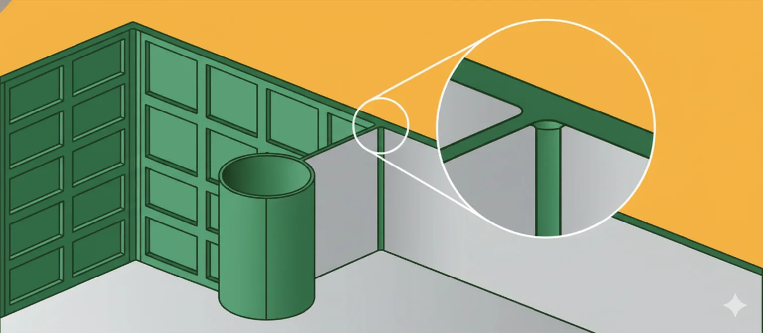
Po ponad 20 latach zmagań z przewężkami w formowaniu wtryskowym widziałem chyba każdy możliwy błąd przy ich usuwaniu — a jest ich naprawdę wiele. Przewężki to kanały doprowadzające stopione tworzywo do gniazda formy, lecz po uformowaniu detalu stają się zbędnym występem wymagającym precyzyjnego odcięcia. Błąd może spowodować ślady naprężeń1, problemy wymiarowe albo wygląd detalu przypominający efekt pracy rębaka. W tym artykule znajdziesz wszystko, co trzeba wiedzieć o usuwaniu przewężek: od podstawowych narzędzi ręcznych przydatnych w małych seriach po zaawansowane systemy automatyczne, których opłacalność zależy od wielkości produkcji.
- Rodzaj przewężki określa sposób jej usuwania — przewężki tunelowe oddzielają się samoczynnie, natomiast przewężki bezpośrednie wymagają ręcznego odcięcia
- Wielkość produkcji determinuje decyzję o automatyzacji — powyżej 50 000 części zrobotyzowane odcinanie wlewów zwraca poniesione nakłady
- Wymagania dotyczące śladu po przewężce determinują nakłady na oprzyrządowanie — części dekoracyjne wymagają czystszego rozwiązania przewężki
- Dobór materiału wpływa na trudność oddzielania wlewu — kruche tworzywa, takie jak PC, wymagają łagodniejszego odcinania przewężki niż elastyczny PP
Jakie są rodzaje przewężek w formowaniu wtryskowym?
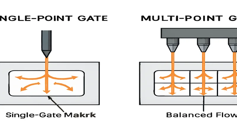
Sześć głównych typów wlewów stosowanych w formowaniu wtryskowym to wlew bezpośredni, krawędziowy, tunelowy, punktowy, wachlarzowy i membranowy. Każdy pozostawia inny ślad i ma inną trudność usuwania. Nie można omawiać usuwania wlewu bez wcześniejszego rozpoznania jego typu.
Jeśli porównujesz dostawców lub planujesz zakupy, nasz przewodnik po wyborze dostawcy usług formowania wtryskowego omawia przygotowanie zapytania ofertowego, kwalifikację i kontrolę ryzyka handlowego.
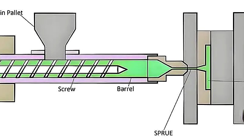
Przewężka bezpośrednia/wlewowa
Najcięższy kaliber wśród przewężek — duże, widoczne i subtelne mniej więcej jak pociąg towarowy. Przewężki bezpośrednie łączą główną tuleję wlewową wprost z częścią i mają zwykle średnicę 3–8 mm. Stosuję je do dużych, grubościennych części, gdy potrzebne jest maksymalne natężenie przepływu, a wygląd śladu po przewężce nie ma znaczenia. Przykładem są zderzaki samochodowe lub duże obudowy, w których miejsce doprowadzenia tworzywa jest ukryte albo później obrabiane. Usunięcie przewężki jest proste — piłą ręczną, taśmową lub przez obróbkę CNC. Pozostałość jest znaczna (wypukłość 2–6 mm), dlatego przewężki bezpośrednie należy stosować wyłącznie tam, gdzie dostępna jest odpowiednia powierzchnia i dopuszczono późniejszą obróbkę.
Przewężka krawędziowa
To podstawowy typ przewężki w większości zastosowań. Przewężka krawędziowa doprowadza tworzywo do detalu od strony linii podziału i ma zazwyczaj 0.5-2.0mm grubości oraz 2-6mm szerokości. Jest uniwersalnym rozwiązaniem wśród przewężek — wszechstronnym, niezawodnym i łatwym do usunięcia standardowymi cążkami. Stosuję przewężki krawędziowe prawdopodobnie w 60% projektowanych przez nas form. Pozostałość po przewężce jest możliwa do opanowania (ma wysokość 0.1-0.5mm) i zwykle można ją usunąć gratownikiem. Kluczowe znaczenie ma umiejscowienie przewężki — należy ją umieścić tam, gdzie pozostałość nie wpłynie na funkcję ani wygląd detalu.
Wlew tunelowy
Teraz pora na „magiczną” przewężkę, która znika sama. Przewężki tunelowe biegną pod linią podziału i są automatycznie odcinane podczas wypychania detalu. Typowa średnica wynosi 0.8-1.5 mm, a pozostałość jest minimalna (0.05-0.2 mm). To doskonałe rozwiązanie do produkcji wielkoseryjnej, w której ręczne usuwanie przewężek generowałoby zbyt wysokie koszty pracy. Jest jednak pewien warunek: forma wtryskowa wymaga precyzyjnej geometrii. Długość tunelu powinna być 2-3 razy większa od średnicy przewężki, a kąt odłamania musi być idealnie dobrany, inaczej pozostaną nierówne ślady.
Przewężka punktowa
Precyzyjne narzędzie wśród przewężek. Przewężki punktowe są bardzo małe (średnica 0.3–0.8 mm) i wchodzą od strony gniazda, pozostawiając minimalny ślad. Są idealne do części dekoracyjnych, na których ślady przewężki są niepożądane. Usuwanie wymaga wprawy — ostrych cążek lub specjalnych obcinaków. Ślad jest niewielki, lecz wymaga starannego wykończenia, aby uniknąć zapadnięć lub koncentracji naprężeń. Stosuję przewężki punktowe w wyrobach medycznych, obudowach elektroniki i wszędzie tam, gdzie wygląd jest ważniejszy niż łatwość przetwarzania.
Punkt wtrysku wachlarzowy
Popularne rozwiązanie do szerokich, cienkich detali. Przewężki wachlarzowe rozprowadzają tworzywo na dużej szerokości (zwykle mają 0.3-0.8 mm grubości i 10-50 mm szerokości), ograniczając linie łączenia i poprawiając wykończenie powierzchni2. Stosuje się je na przykład w pokrywach laptopów i samochodowych panelach wykończeniowych. Ich usuwanie jest żmudne — do równego przycięcia całej szerokości potrzebny jest ostry nóż i cierpliwość. Pozostałością jest cienki grzbiet wymagający ostrożnego szlifowania lub frezowania. Przewężki wachlarzowe są pracochłonne, ale gdy szeroki detal trzeba wypełnić równomiernie, dodatkowy wysiłek się opłaca.
Wlew przeponowy/tarczowy
Specjalistyczna przewężka do detali cylindrycznych, takich jak butelki lub pojemniki. Otacza cały obwód detalu, zapewniając wyjątkowo równomierne wypełnianie. Grubość przewężki wynosi zwykle 0.2-0.6mm, a jej usunięcie wymaga starannego okrawania nożem na całym obwodzie. Pozostałością jest cienki pierścień, który w zastosowaniach o krytycznych wymaganiach często trzeba obrabiać na tokarce. Przewężki membranowe zapewniają znakomitą charakterystykę napełniania, lecz ich oczyszczanie jest pracochłonne, chyba że można pozwolić sobie na obróbkę wykończeniową CNC.
Jak ręcznie usuwać przewężki z formowanych części?
Podstawowe narzędzia do ręcznego usuwania przewężek to szczypce ręczne, obcinaki boczne, gratowniki i obcinaki do przewężek. Właściwa technika decyduje o tym, czy uzyska się profesjonalny rezultat, czy brak.
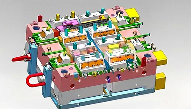
Szczypce ręczne i obcinaki boczne
Podstawowe narzędzia do usuwania przewężek krawędziowych o grubości do 2mm. Polecam szczypce Xuron lub Lindstrom — kosztują wprawdzie 3-4 razy więcej niż szczypce ze sklepu narzędziowego, ale przez lata zapewniają czyste cięcie. Kluczowe znaczenie mają kąt ostrza i technika cięcia. Ustaw szczypce prostopadle do przewężki, a nie pod kątem, i wykonaj jedno płynne cięcie. Częściowe nacięcia tworzą koncentracje naprężeń i nieestetyczne pozostałości. W przypadku ABS i PC utrzymuję ostrza w stanie idealnej ostrości za pomocą pasty diamentowej o gradacji 1000. Tępe ostrza miażdżą i rozrywają materiał zamiast go ciąć, zwłaszcza w przypadku wytrzymałych tworzyw, takich jak POM lub nylon.
Noże uniwersalne i ostrza żyletkowe
Niezbędny do przewężek wachlarzowych i cienkich wypływek. Należy bezwzględnie używać świeżych ostrzy — wymieniam je co 50-100 cięć, zależnie od materiału. W przypadku materiałów takich jak PS i ABS stosuje się technikę nacięcia i przełamania, natomiast w przypadku materiałów elastycznych, takich jak TPE — cięcie i odrywanie. Ostrze należy prowadzić pod małym kątem (15-20 stopni), aby uniknąć zagłębiania się w powierzchnię części. Do części o krytycznym wyglądzie używam skalpeli chirurgicznych z ostrzami #11 — są ostrzejsze niż standardowe noże techniczne i zapewniają czystsze cięcie cienkich przewężek.
Narzędzia do gratowania i skrobaki
Zestaw narzędzi do usuwania pozostałości przewężek. Gratowniki z wymiennymi ostrzami dobrze usuwają pozostałości 0.1-0.3mm z większości tworzyw termoplastycznych. Sekret to lekkie przejścia — nie próbuj usuwać całości jednym ruchem. Do materiałów z włóknem szklanym używaj ostrzy węglikowych; stal szybkotnąca szybko tępi się na ściernych napełniaczach. Zakrzywione skrobaki lepiej działają na powierzchniach cylindrycznych, a proste ostrza na płaskich. Zawsze skrob w kierunku grubszej części, aby uniknąć koncentracji naprężeń.
Specjalistyczne obcinaki wlewów
W wysokonakładowych operacjach ręcznych specjalistyczne obcinaki do wlewek szybko się zwracają. Pneumatyczne obcinaki do wlewek mogą obrabiać 500-1000 części na godzinę przy zachowaniu stałej jakości – to 5-10 razy szybciej niż obcinanie szczypcami ręcznymi. Początkowa inwestycja wynosi $1500-5000, lecz przy produkcji przekraczającej 10,000 części rocznie oszczędności robocizny uzasadniają ten koszt. Narzędzia te wykorzystują precyzyjne wykrojniki dopasowane do konkretnej geometrii wlewka, zapewniając powtarzalną jakość śladu po wlewku, nieosiągalną przy użyciu narzędzi ręcznych.
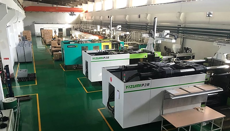
W naszym zakładzie w Szanghaju pracuje 47 wtryskarek o sile zwarcia od 90T do 1850T. Z doświadczenia wiem, że wybór metody oddzielania wlewków może przesądzić o opłacalności produkcji. W ciągu ponad 20 lat pracy w branży formowania wtryskowego widziałem zakłady ponoszące straty tylko dlatego, że nie dopasowały metody oddzielania wlewków do wielkości produkcji i wymagań jakościowych.
Jakie istnieją metody automatycznego usuwania przewężek?
Dominuje pięć zautomatyzowanych metod: zrobotyzowane oddzielanie wlewów3, przycinanie CNC, automatyczne oddzielanie wlewów z kanałem gorącym4, cięcie laserowe i cięcie ultradźwiękowe. Kluczowe jest dopasowanie poziomu automatyzacji do wielkości produkcji i złożoności części.
Robotyczne systemy odcinania wlewów
Roboty sześcioosiowe ze specjalistycznymi narzędziami tnącymi mogą obsługiwać złożone geometrie przewężek, trudne dla operatorów. Typowe stanowisko kosztuje $150,000-300,000, ale może obrabiać 1000-2000 części na godzinę przy stałej jakości. Najlepiej sprawdza się przy częściach z co najmniej 3 przewężkami lub złożoną geometrią, gdy ręczne usunięcie układu wlewowego trwa ponad 30 sekund na część. Programowanie jest czasochłonne — dla złożonych części należy przewidzieć 2-4 tygodnie — lecz po dopracowaniu procesu wyniki są powtarzalne 24/7. Robot nie męczy się, nie korzysta ze zwolnień chorobowych ani świadczeń pracowniczych.
Operacje przycinania CNC
Obróbka CNC ma uzasadnienie w przypadku części wymagających precyzyjnego usunięcia pozostałości przewężki lub gdy obszar przewężki i tak wymaga wykonania cech obróbkowych. Typowy czas cyklu wynosi 30-180 sekund zależnie od złożoności, a koszt oprzyrządowania do mocowania i programowania to $5,000-25,000. CNC sprawdza się doskonale w przypadku przewężek bezpośrednich w częściach motoryzacyjnych lub lotniczych, gdy obszar przewężki i tak jest obrabiany do wymiarów końcowych. Ograniczeniem jest czas cyklu — obróbkę CNC uzasadnia wysoka wartość części ($5+ za sztukę).
Automatyczne oddzielanie przewężek w kanale gorącym
Rolls Royce wśród systemów doprowadzania tworzywa. Systemy gorącokanałowe z przewężkami zaworowymi całkowicie eliminują ręczne oddzielanie wlewków, ponieważ sterują przepływem tworzywa za pomocą ogrzewanych dysz. Początkowy koszt oprzyrządowania jest o 40-60% wyższy niż w przypadku systemów zimnokanałowych, lecz eliminuje się całość pracy związanej z oddzielaniem wlewków oraz odpady materiałowe z kanałów. Próg rentowności osiąga się zwykle przy 100,000-500,000 części, zależnie od ich wielkości i złożoności. Konserwacja ma kluczowe znaczenie — należy zakładać roczny koszt $5,000-15,000 na wymianę elementów grzejnych i serwis sterowników.
Cięcie laserowe i ultradźwiękowe
Nowe technologie precyzyjnego oddzielania wlewów. Cięcie laserowe zapewnia wyjątkowo czyste krawędzie i minimalną strefę wpływu ciepła, dlatego świetnie nadaje się do części medycznych i optycznych. Urządzenia kosztują 200 000–500 000 USD, co ogranicza zastosowanie do części o wysokiej wartości. Cięcie ultradźwiękowe dobrze sprawdza się przy cienkich przewężkach w elastycznych materiałach; urządzenia są tańsze (50 000–150 000 USD), ale obróbka wolniejsza. Obie technologie wciąż znajdują swoją niszę w świecie formowania wtryskowego.
| Metoda | Koszt pracy | Koszt sprzętu | Koszt całkowity | Wolumen progu rentowności |
|---|---|---|---|---|
| Ręczne cęgi tnące | $25-45 | $0.05 | $25.05-45.05 | 0-10 tys. detali/rok |
| Nożyce pneumatyczne | $15-25 | $0.50 | $15.50-25.50 | 10K-50K części/rok |
| Zrobotyzowane usuwanie bramek | $5-10 | $2-5 | $7-15 | 50 tys.+ detali/rok |
| Bramy Podwodne | $0 | $0.20 | $0.20 | 25K+ części/rok |
Jak konstrukcja bramki wpływa na trudność usunięcia?
Trudność usunięcia jest określana przez cztery czynniki: pole powierzchni bramki, jej lokalizację, skurcz materiału oraz przejścia grubości ścianki w strefie bramki.
Rozmiar bramki a jakość śladu
Między wielkością przewężki a jakością pozostałości po wlewie występuje zależność odwrotna — większe przewężki łatwiej czysto odciąć, ale pozostawiają większy ślad. W większości zastosowań optymalna grubość przewężki krawędziowej wynosi 0.5-1.0mm. Cieńsze przewężki (0.3mm) pozostawiają minimalny ślad, lecz rozrywają się podczas usuwania, szczególnie w przypadku ciągliwych materiałów. Grubsze przewężki (1.5mm+) można czysto odciąć, ale pozostawiają wyraźne ślady wymagające obróbki wykańczającej. Znaczenie ma również materiał — miękkie tworzywa, takie jak PE, pozwalają stosować cieńsze przewężki, natomiast sztywne materiały, takie jak PC, wymagają odpowiedniej grubości, aby uniknąć pękania naprężeniowego podczas usuwania.
Strategia lokalizacji bramki
Rozmieszczenie przewężek przypomina grę w szachy, a nie w warcaby. Przewężki należy umieszczać tam, gdzie ich ślady nie wpłyną na funkcjonalność ani wygląd — w narożnikach wewnętrznych, na powierzchniach bez kontaktu użytkowego lub w miejscach, które zostaną połączone z innymi elementami albo pomalowane. Należy unikać obszarów silnie obciążonych, w których ślady po przewężkach powodują koncentrację naprężeń. W przypadku części dekoracyjnych przewężki należy lokować na powierzchniach niewidocznych po montażu końcowym. Widziałem estetyczne detale zniszczone przez przewężki umieszczone na powierzchniach klasy A tylko dlatego, że konstruktor formy nie uwzględnił końcowego zastosowania.
Efekty kurczenia się materiału
Różne materiały kurczą się różnie wokół bram, wpływając na wygląd pozostałości i trudność usunięcia. Materiały półkrystaliczne, takie jak PP i POM, tworzą wgłębienia wokół grubych bram ze względu na duży skurcz (1,5-2,5%). Materiały amorficzne, takie jak ABS i PC, mają mniejszy skurcz (0,4-0,8%) i tworzą bardziej jednolite pozostałości. Materiały wypełnione szkłem wymagają szczególnego rozważenia – włókna powodują ścierne zużycie narzędzi tnących i mogą prowadzić do chropowatych powierzchni pozostałości, jeśli nie są właściwie przecięte.
Przejścia grubości ścianki
Ostre zmiany grubości w pobliżu bramek powodują problemy z usuwaniem i wady detalu. Przejście z bramki na ściankę detalu powinno być stopniowe – tam, gdzie to możliwe, stosuję stożkowanie 3:1 lub 4:1. Nagłe przejścia powodują koncentrację naprężeń, co może prowadzić do pękania detali podczas odbramkowania, szczególnie w materiałach kruchych lub przy niskich temperaturach. Bramka powinna wpływać do najgrubszej sekcji w danym obszarze, aby zminimalizować spadek ciśnienia i potencjał powstania wklęśnięcia.
Kiedy wybierać projekty bramek samoodbramkowujących?
Samoczynnie odcinające się bramy to święty Graal formowania wtryskowego – części odseparowujące się od układów wypływowych automatycznie, bez ręcznej interwencji. Ale jak większość dobrych rzeczy, mają swoje kompromisy, które musisz zrozumieć przed podjęciem decyzji.
Bramki tunelowe, które oddzielają się automatycznie
Przewężki tunelowe działają poprzez utworzenie kontrolowanego miejsca przełamania, które zostaje odcięte podczas wypychania części. Kluczowe parametry to długość tunelu (2-3x średnica przewężki), kąt odłamania (zwykle 15-30 stopni) i dobór materiału. Kruche materiały, takie jak PS i SAN, sprawdzają się znakomicie, natomiast wytrzymałe materiały, takie jak PC i POM, mogą sprawiać trudności. Przewężki tunelowe zapewniały mi bardzo dobre wyniki w przypadku obudów elektronicznych, zabawek i produktów konsumenckich, gdzie czas cyklu jest ważniejszy niż idealny wygląd śladu po przewężce. Ze względu na złożoną geometrię oprzyrządowanie jest droższe o 15-25%, ale eliminuje całość pracy związanej z usuwaniem wlewków.
Zasuwane bramki z gorącym kanałem
Bramy zaworowe wykorzystują ogrzewane sondy do sterowania przepływem tworzywa, całkowicie eliminując układy wypływowe. Każda brama ma indywidualną kontrolę, umożliwiając sekwencyjne napełnianie dla złożonych części lub form rodzinnych. Technologia jest dojrzała i niezawodna przy prawidłowej konserwacji, ale początkowa inwestycja jest znaczna – $5,000-15,000 na bramę w zależności od rozmiaru i złożoności. Bramy zaworowe mają sens w produkcji wielkoseryjnej (100 000+ części rocznie) lub gdy koszt materiału układu wypływowego jest znaczący. Wymagania konserwacyjne są realne – spodziewaj się kwartalnych kontroli elementów grzejnych i rocznej kalibracji sterowników.
Systemy Bram Termicznych
Przewężki termiczne wykorzystują różnice temperatury do tworzenia kontrolowanych punktów oddzielenia. Koncepcja jest elegancka — po wypełnieniu podgrzewa się odcinek kanału, wywołując rozszerzalność cieplną, która zrywa połączenie. W praktyce rozwiązanie jest bardziej złożone i wymaga precyzyjnej kontroli temperatury oraz czasu. Widziałem udane zastosowania w opakowaniach i wyrobach medycznych, lecz technologia nadal się rozwija. Koszt wyposażenia jest umiarkowany ($25,000-75,000), ale opracowanie procesu może być czasochłonne.
Uzasadnienie inwestycji
Obliczenia dla układów samoczynnie odcinających wlew są proste, lecz często pomijane. Oblicz bieżący koszt robocizny związanej z odcinaniem wlewu na część, pomnóż go przez roczny wolumen i porównaj z dodatkową inwestycją w oprzyrządowanie. Uwzględnij poprawę jakości, skrócenie cyklu i wyeliminowany koszt materiału kanałów. Dla większości zastosowań próg rentowności wynosi 25 000–100 000 części, zależnie od kosztów pracy i złożoności części. Nie zapomnij o konserwacji — układy samoczynnego odcinania wymagają bardziej złożonego oprzyrządowania i regularnego serwisu.
Jakie kontrole jakości są potrzebne po usunięciu bramki?
Cztery niezbędne kontrole po usunięciu to inspekcja wizualna, pomiar wymiarowy, test chropowatości powierzchni oraz badanie śladów naprężeń.
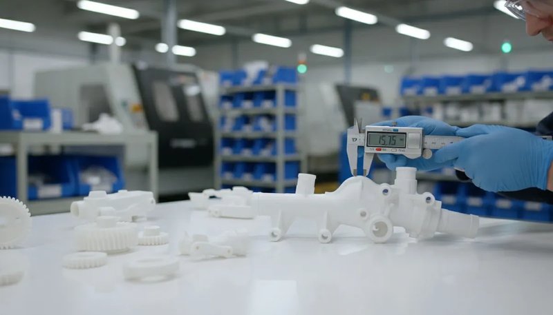
Standardy kontroli wizualnej
Opracuj jasne standardy wizualne dla akceptowalnego wyglądu pozostałości bramy. Dokumentuj za pomocą fotografii przedstawiających stan akceptowalny, graniczny i odrzucony. Szkol operatorów w rozpoznawaniu bielenia naprężeniowego, niepełnych cięć i uszkodzeń powierzchni. Stosuj spójne oświetlenie – 500-1000 luksów przy temperaturze barwowej 6500K ujawnia wady, które mogą być przeoczone przy standardowym oświetleniu fabrycznym. Dla części kosmetycznych sprawdzaj w warunkach zbliżonych do środowiska końcowego użytkowania – części samochodowe pod oświetleniem samochodowym, elektronikę użytkową pod typowym oświetleniem domowym.
Weryfikacja wymiarowa
Usunięcie bramki może wpłynąć na wymiary detalu poprzez odprężenie lub usunięcie materiału. Sprawdź krytyczne wymiary w odległości 0,1 mm od lokalizacji bramki przy użyciu wzorcowanego sprzętu pomiarowego. W przypadku części cienkościennych naprężenia związane z odcinaniem bramki mogą powodować natychmiastowe zmiany wymiarowe lub długoterminowe odkształcenia. Ustal stabilność wymiarową poprzez pomiar detali bezpośrednio po odbramkowaniu, a następnie po 24-48 godzinach. Detały, które przesuwają się o więcej niż 0,05 mm, wskazują na nadmierne naprężenia odbramkowania lub słaby projekt bramki.
Wymagania dotyczące wykończenia powierzchni
Wykończenie powierzchni wypływu bramki wpływa zarówno na wygląd, jak i funkcję. Szorstkie wypływy tworzą koncentracje naprężeń i punkty przedwczesnego uszkodzenia. Użyj mierników chropowatości powierzchni, aby ustalić ilościowe standardy – zwykle Ra 1.6-6.3 μm dla powierzchni funkcjonalnych, Ra 0.4-1.6 μm dla powierzchni kosmetycznych. Szlifuj lub obrabiaj szorstkie wypływy zgodnie ze specyfikacją, zamiast akceptować niską jakość. Koszt pracy związany z właściwym wykończeniem jest zazwyczaj niższy niż koszt awarii w terenie lub skarg klientów.
Wykrywanie typowych wad
Przeszkol kontrolerów w rozpoznawaniu zbielenia naprężeniowego (wskazuje na przeciążenie podczas cięcia), zapadnięć (skurcz materiału wokół grubych przewężek), różnic barwy (uszkodzeń cieplnych spowodowanych tępymi narzędziami tnącymi) oraz niepełnego oddzielenia (częściowych nacięć tworzących koncentratory naprężeń). W przypadku małych przewężek stosuj powiększenie — zwykle 2-4x wystarcza do oceny jakości cięcia. Odrzucaj detale z jakimkolwiek zbieleniem naprężeniowym w obszarach widocznych lub koncentracją naprężeń w obszarach funkcjonalnych. Wady te nie zanikają z czasem, lecz się pogłębiają.
"Systemy gorącokanałowe eliminują wszystkie operacje usuwania przewężek"True
Prawidłowo działające systemy gorących kanałów z bramkami zaworowymi całkowicie eliminują fizyczne bramki, nie wymagając operacji usuwania bramek. Przepływ plastiku jest kontrolowany przez podgrzewane sondy, które szczelnie się zamykają.
"Przewężki tunelowe zawsze zapewniają lepsze wykończenie powierzchni niż przewężki krawędziowe"False
Choć bramki tunelowe mogą zapewniać doskonałą jakość śladu, to wykończenie powierzchni zależy od prawidłowej geometrii tunelu, doboru materiału i parametrów przetwórstwa. Źle zaprojektowane bramki tunelowe mogą nierówno się urywać, pozostawiając szorstkie ślady gorsze niż dobrze odcięte bramki brzegowe.
Zrozumienie relacji między projektem bramki a skutecznością jej usuwania pomaga inżynierom podejmować lepsze decyzje na wczesnym etapie cyklu rozwoju produktu. W praktyce najbardziej udane projekty wtryskowe uwzględniają strategię odbramkowania już podczas wstępnego przeglądu DFM (Design for Manufacturing), na długo przed wykonaniem narzędzia. Takie proaktywne podejście zapobiega kosztownym modyfikacjom formy i opóźnieniom w produkcji, które często występują, gdy usunięcie bramki traktowane jest jako późniejszy dodatek, a nie wymóg projektowy.
"Metodę usuwania przewężki należy określić na etapie projektowania formy"True
Konstrukcja bramki bezpośrednio wpływa na trudność usunięcia, wielkość wypływu i opłacalność procesu. Decydowanie o metodzie usunięcia po zakończeniu obróbki często prowadzi do nieoptymalnych wyników i wyższych kosztów produkcji.
"Większe przewężki zawsze łatwiej usunąć bez pozostawiania śladów"False
Choć większe bramki zapewniają więcej materiału do uchwycenia podczas cięcia, to wymagają również większej siły cięcia i pozostawiają większe ślady. Bardzo duże bramki mogą powodować koncentrację naprężeń i pękanie podczas usuwania, szczególnie w materiałach kruchych.
Często zadawane pytania
Często zadawane pytania
Co to jest wypływ bramki w formowaniu wtryskowym?
Pozostałość po przewężce to niewielki występ materiału pozostający na wyprasce po usunięciu przewężki. Można go porównać do „pępka” w miejscu, w którym część była połączona z układem kanałów wlewowych. Wielkość pozostałości zależy od rodzaju przewężki i sposobu jej usuwania — przewężki tunelowe pozostawiają minimalne ślady (0.05-0.2mm), natomiast przewężki bezpośrednie mogą pozostawić znaczne wypukłości (2-6mm). Jakość miejsca po przewężce wpływa zarówno na wygląd części, jak i na jej integralność strukturalną, dlatego właściwa technika usuwania ma kluczowe znaczenie dla zachowania zgodności części ze specyfikacją.
Czy można usunąć bramki formowania wtryskowego bez specjalnych narzędzi?
Dla małych bramek i niskich nakładów podstawowe narzędzia jak ostre noże lub standardowe obcinacze mogą działać, ale wyniki będą niespójne i pracochłonne. Bramki krawędziowe o grubości do 1mm można ciąć za pomocą wysokiej jakości boczków, choć specjalistyczne obcinacze bramek dają czystsze wyniki. Jednak dla nakładów produkcyjnych powyżej kilkuset części koszt pracy i problemy z jakością sprawiają, że odpowiednie narzędzia do usuwania bramek są niezbędne. Próba oszczędzania na narzędziach zazwyczaj kosztuje więcej w czasie pracy i odrzutach niż inwestycja w odpowiedni sprzęt od samego początku.
Czy usunięcie przewężki wpływa na dokładność wymiarową części?
Tak, nieprawidłowe usuwanie przewężki może wpływać na dokładność wymiarową. Cięcie zbyt blisko powierzchni części może usunąć materiał ze ścianki i utworzyć obszar o zbyt małym wymiarze, wykraczającym poza tolerancję. Z kolei pozostawienie zbyt dużej pozostałości przewężki dodaje niepożądany materiał, który utrudnia montaż. Kluczowe jest kontrolowanie głębokości cięcia — zwykle w granicach ±0,1 mm względem powierzchni części. W przypadku części o wąskich tolerancjach po usunięciu przewężki trzeba przeprowadzić kontrolę wymiarową w jej miejscu, aby potwierdzić zgodność części z dokumentacją i wymaganiami funkcjonalnymi.
Jaki typ przewężki najlepiej nadaje się do automatycznego odcinania?
Przewężki tunelowe są idealne do automatycznego odcinania, ponieważ zaprojektowano je tak, aby odrywały się podczas wypychania wypraski bez dodatkowych operacji. Tunel przewężki przebiega pod linią podziału i przełamuje się w określonym, osłabionym miejscu, pozostawiając minimalny ślad (zwykle 0.05-0.2mm). Skuteczność zależy od właściwej geometrii tunelu — jego długość powinna wynosić 2-3-krotność średnicy przewężki, przy odpowiednich kątach odłamania. Istotny jest również dobór materiału: kruche tworzywa, takie jak PS, sprawdzają się lepiej niż tworzywa ciągliwe, takie jak PC. W układach gorącokanałowych przewężki zaworowe całkowicie eliminują konieczność odcinania dzięki sterowaniu przepływem za pomocą ogrzewanych iglic.
Ile kosztuje zautomatyzowane urządzenie do usuwania pozostałości przewężek?
Koszt automatycznych urządzeń do usuwania przewężek jest bardzo zróżnicowany w zależności od stopnia złożoności i wymaganej wydajności. Podstawowe stanowisko z obcinakiem pneumatycznym kosztuje około 2,000–5,000 USD i jest przeznaczone do produkcji małoseryjnej. Ceny zrobotyzowanych stanowisk do usuwania przewężek zaczynają się od około 50,000 USD i mogą przekraczać 200,000 USD w przypadku systemów wieloosiowych ze zintegrowanym prowadzeniem wizyjnym. Systemy cięcia laserowego kosztują 80,000–150,000 USD. Zwrot z inwestycji zależy od oszczędności kosztów pracy, ograniczenia braków i wzrostu wydajności, przy czym większość systemów zwraca się w ciągu 12–24 miesięcy przy rocznej produkcji przekraczającej 100,000 części.
Czy istnieją konstrukcje przewężek, które eliminują konieczność ich usuwania?
Tak, kilka konstrukcji przewężek eliminuje ręczne usuwanie. Iglicowe systemy gorącokanałowe sterują przepływem tworzywa ogrzewanymi trzpieniami i zamykają się czysto, bez fizycznej przewężki do usunięcia. Prawidłowo zaprojektowane przewężki tunelowe odcinają się automatycznie podczas wyrzutu. Niektóre systemy termiczne wykorzystują kontrolowane ogrzewanie do przerwania połączenia z wlewem. Wymagają jednak większej początkowej inwestycji w oprzyrządowanie (15-60% więcej) i mogą wymagać bieżącej konserwacji. Decyzja zależy od wolumenu, kosztów pracy i wymagań jakościowych. W produkcji wielkoseryjnej eliminacja odcinania wlewów zwykle uzasadnia dodatkowy koszt.
Co powoduje białe ślady naprężeń w pobliżu miejsc usunięcia przewężki?
Białe ślady naprężeń powstają, gdy siły cięcia przekraczają granicę plastyczności materiału, powodując orientację łańcuchów cząsteczkowych i zmianę rozpraszania światła. Typowe przyczyny to tępe narzędzia, które zgniatają zamiast ciąć, nadmierna siła cięcia, niewłaściwe kąty cięcia lub cięcie zamrożonych detali poniżej temperatury zeszklenia. Szczególnie podatne są kruche materiały, takie jak PS i sztywne PVC. Zapobieganie obejmuje stosowanie ostrych narzędzi, prawidłowej techniki cięcia, ogrzewanie detali do temperatury pokojowej przed cięciem oraz projektowanie przewężek o grubości zapewniającej czyste odcięcie. Zbielenie naprężeniowe jest trwałe i w widocznych miejscach zwykle wymaga odrzucenia detalu.
Usuwanie przewężki może wydawać się prostą operacją wtórną, ale właśnie na tym etapie dobre części stają się doskonałe — albo doskonałe części zostają zniszczone. Kluczowe jest uwzględnienie usuwania przewężki podczas projektowania formy, a nie dopiero po rozpoczęciu produkcji. Dobierz odpowiedni typ przewężki do wymaganego wolumenu i jakości, zainwestuj we właściwe narzędzia i szkolenia oraz ustal jasne standardy jakości. Pamiętaj, że najtańsza metoda usuwania przewężki nie zawsze jest najbardziej ekonomiczna po uwzględnieniu czasu pracy, problemów jakościowych i zadowolenia klienta.
Chcesz zoptymalizować usuwanie przewężek? W ZetarMold od początku projektujemy formy z myślą o odcinaniu wlewków. Nasi inżynierowie mogą ocenić obecny proces i zalecić usprawnienia oszczędzające czas i koszty oraz poprawiające jakość. Skontaktuj się z nami, aby omówić, jak właściwa konstrukcja i strategia usuwania przewężek mogą zwiększyć wydajność produkcji.
naprężenie: Zbielenie naprężeniowe jest wizualnym wskaźnikiem mikrokystalicznych uszkodzeń części polimerowych, mierzonych w MPa jako resztkowe naprężenie wewnętrzne w pobliżu przewężek. ↩
wykończenie powierzchni: Chropowatość powierzchni definiuje się jako odchylenia mierzonej powierzchni od jej idealnego kształtu w kierunku wektora normalnego; podaje się ją w mikrometrach (wartości Ra). ↩
robotyzacja: Robotyzowane oddzielanie wlewów polega na użyciu programowalnych, wieloosiowych ramion do powtarzalnego i precyzyjnego oddzielania wyprasek od kanałów i przewężek. ↩
kanał gorący: System kanałów gorących to zespół podgrzewanych elementów stosowany w formach wtryskowych, który doprowadza stopione tworzywo do gniazd formy i utrzymuje polimer w stanie płynnym. ↩