Look, after 20+ years of wrestling with injection molding gates, I’ve seen every conceivable way to mess up gate removal – and trust me, there are plenty. Gates are the channels that feed molten plastic into your mold cavity, but once your part is molded, they become the unwanted appendage that needs surgical removal. Get it wrong, and you’ll have ストレス1 marks, dimensional issues, or parts that look like they went through a wood chipper. This article covers everything you need to know about gate removal – from the basic hand tools that’ll save your bacon on low-volume runs to the fancy automated systems that’ll make your accountant either smile or cry, depending on your production volumes.
- Gate type determines removal method — submarine gates self-degating, while direct gates need manual cutting
- Production volume drives automation decision — above 50,000 parts, robotic degating pays for itself
- Gate vestige requirements dictate your tooling investment — cosmetic parts need cleaner gate design
- Material choice affects removal difficulty — brittle plastics like PC need gentler degating than flexible PP
What Are the Different Types of Injection Molding Gates?
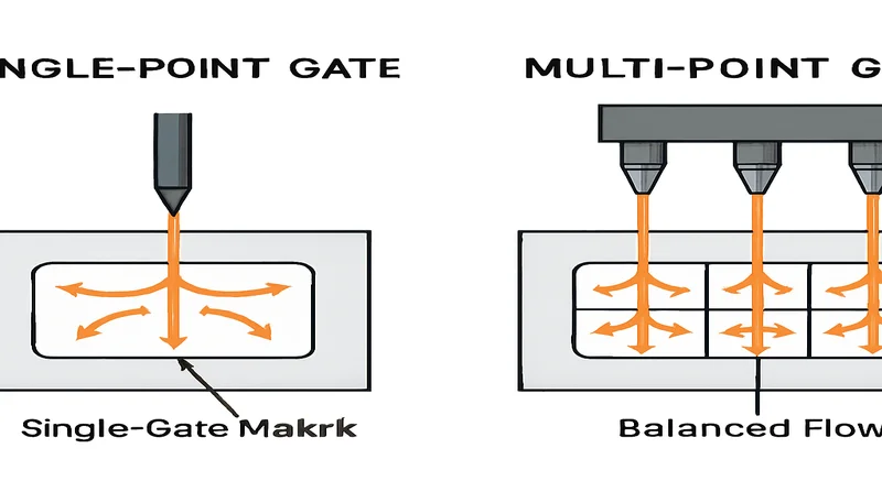
The six main injection molding gate types are direct, edge, submarine, pin-point, fan, and diaphragm gates. Each has a distinct vestige profile and removal difficulty. You can’t talk gate removal without understanding what you’re dealing with first.
If you are comparing vendors or planning procurement, our injection molding supplier sourcing guide covers RFQ prep, qualification, and commercial risk checks.

Direct/Sprue Gate
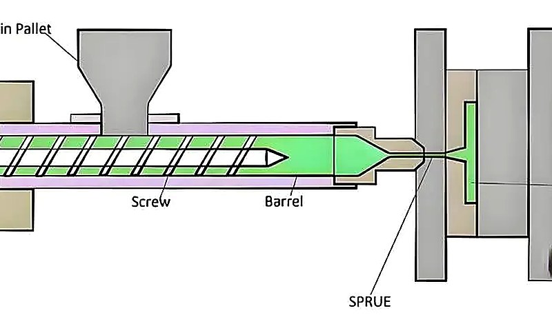
The sledgehammer of gates – big, obvious, and about as subtle as a freight train. Direct gates connect straight from the main sprue to your part, typically 3-8mm in diameter. I use these for large, thick parts where you need maximum flow rate and don’t care about gate vestige appearance. Think automotive bumpers or large housings where the gate area gets hidden or machined away. Removal is straightforward – hacksaw, band saw, or CNC machining. The vestige is substantial (2-6mm raised area), so only use direct gates where you can afford the real estate and post-machining.
エッジゲート
Your bread-and-butter gate for most applications. Edge gates enter the part from the parting line, typically 0.5-2.0mm thick and 2-6mm wide. They’re the Swiss Army knife of gates – versatile, reliable, and easy to remove with standard nippers. I spec edge gates for probably 60% of the molds we design. Gate vestige is manageable (0.1-0.5mm high), and you can usually clean it up with a deburring tool. The key is gate placement – put it where the vestige won’t affect function or appearance.
Submarine/Tunnel Gate
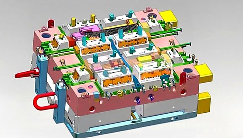
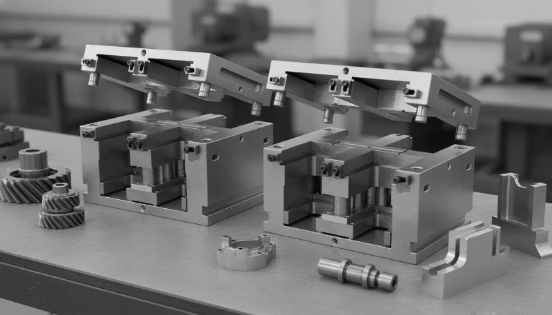
Now we’re talking – the magician’s gate that disappears on its own. Submarine gates tunnel under the parting line and shear off automatically when you eject the part. Typical diameter is 0.8-1.5mm, and the vestige is minimal (0.05-0.2mm). These beauties are perfect for high-volume production where manual degating would kill your labor costs. The catch? Your 射出成形金型 needs precise geometry – the tunnel length should be 2-3 times the gate diameter, and the break angle needs to be spot-on or you’ll get rough vestiges.
Pin Point Gate
The precision instrument of gates. Pin point gates are tiny (0.3-0.8mm diameter) and enter through the cavity side, leaving minimal vestige. They’re ideal for cosmetic parts where gate marks are unwelcome guests. Removal requires finesse – sharp nippers or specialized gate cutters. The vestige is small but needs careful finishing to avoid sink marks or stress concentrations. I use pin point gates for medical devices, electronics housings, and anywhere appearance matters more than easy processing.
Fan Gate
The crowd-pleaser for wide, thin parts. Fan gates spread the flow across a broad area (typically 0.3-0.8mm thick, 10-50mm wide), reducing weld lines and improving 表面仕上げ2. Think laptop covers or automotive trim panels. Removal is tedious – you’ll need sharp knives and patience to trim the entire width cleanly. The vestige is a thin ridge that needs careful sanding or routing. Fan gates are high-maintenance, but when you need uniform fill across a wide part, they’re worth the extra effort.
Diaphragm/Disk Gate
The specialty gate for cylindrical parts like bottles or containers. The gate surrounds the entire circumference of the part, providing incredibly uniform filling. Gate thickness is typically 0.2-0.6mm, and removal requires careful knife work around the entire perimeter. The vestige is a thin ring that often needs lathe work for critical applications. Diaphragm gates are beautiful for their filling characteristics but are labor-intensive to clean up unless you can afford CNC post-processing.
How Do You Manually Remove Gates from Molded Parts?
The primary manual gate removal tools are hand nippers, side cutters, deburring tools, and gate cutters. Good technique makes the difference between professional results and scrap.

Hand Nippers and Side Cutters
Your primary weapons for edge gates up to 2mm thick. I swear by Xuron or Lindstrom nippers – yeah, they cost 3-4 times more than hardware store cutters, but they’ll give you clean cuts for years. The key is blade angle and cutting technique. Position the nippers perpendicular to the gate, not angled, and cut in one smooth motion. Partial cuts create stress concentrations and ugly vestiges. For ABS and PC, I keep the cutting blades razor-sharp with 1000-grit diamond paste. Dull blades crush and tear rather than cut, especially with tough materials like POM or nylon.
Utility Knives and Razor Blades
Essential for fan gates and thin flash. Use fresh blades religiously – I change them every 50-100 cuts depending on material. The technique is score-and-snap for materials like PS and ABS, but slice-and-peel for flexible materials like TPE. Keep the blade angle low (15-20 degrees) to avoid digging into the part surface. For critical cosmetic parts, I use surgical scalpels with #11 blades – they’re sharper than standard utility blades and give cleaner cuts on thin gates.
Deburring Tools and Scrapers
The cleanup crew for gate vestiges. Deburring tools with replaceable blades work great for removing 0.1-0.3mm vestiges on most thermoplastics. The secret is light passes – don’t try to remove the entire vestige in one stroke. For glass-filled materials, use carbide deburring blades; high-speed steel dulls quickly on abrasive fillers. Curved scrapers work better on cylindrical surfaces, while straight blades handle flat areas. Always scrape toward the thicker section of the part to avoid stress concentrations.
Specialized Gate Cutters
For high-volume manual operations, specialized gate cutters pay for themselves quickly. Pneumatic gate cutters can process 500-1000 parts per hour with consistent quality – that’s 5-10 times faster than hand nippers. The initial investment is $1500-5000, but labor savings justify the cost above 10,000 parts annually. These tools use precise cutting dies matched to your specific gate geometry, giving repeatable vestige quality that hand tools can’t match.
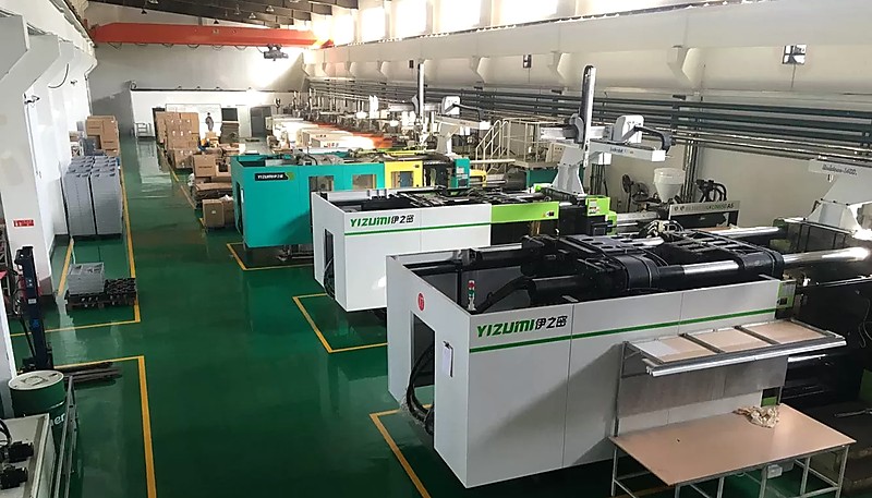
In our Shanghai factory, we run 47 injection molding machines from 90T to 1850T, and I’ve learned that gate removal method selection can make or break your production economics. With 20+ years of injection molding experience, I’ve seen operations lose money simply because they didn’t match the degating method to their volume and quality requirements.
What Automated Gate Removal Methods Exist?
Five automated methods dominate: robotic3 degating, CNC trimming, ホットランナー4 auto-degating, laser cutting, and ultrasonic cutting. The key is matching automation level to production volume and part complexity.
Robotic Degating Systems
Six-axis robots with specialized cutting tools can handle complex gate geometries that would challenge human operators. A typical setup costs $150,000-300,000 but can process 1000-2000 parts per hour with consistent quality. The sweet spot is parts with 3+ gates or complex geometries where manual removal takes over 30 seconds per part. Programming time is significant – expect 2-4 weeks for complex parts – but once dialed in, you’ll get repeatable results 24/7. The robot doesn’t get tired, doesn’t call in sick, and doesn’t need benefits.
CNC Trimming Operations
For parts requiring precise gate vestige removal or where the gate area needs machined features anyway, CNC trimming makes sense. Typical cycle times are 30-180 seconds depending on complexity, with tooling costs of $5,000-25,000 for fixtures and programming. CNC works great for direct gates on automotive or aerospace parts where the gate area gets machined to final dimensions anyway. The limitation is cycle time – you need high part values ($5+ each) to justify CNC processing.
Hot Runner Auto-Degating
The Rolls Royce of gate systems. Hot runner systems with valve gates eliminate manual degating entirely by controlling plastic flow with heated probes. Initial tooling costs are 40-60% higher than cold runner systems, but you eliminate all degating labor and runner material waste. Break-even is typically 100,000-500,000 parts depending on part size and complexity. Maintenance is critical – expect $5,000-15,000 annually for heating element replacement and controller servicing.
Laser and Ultrasonic Cutting
Emerging technologies for precision degating. Laser cutting gives incredibly clean cuts with minimal heat-affected zones, perfect for medical and optical parts. Equipment costs run $200,000-500,000, limiting application to high-value parts. Ultrasonic cutting works well for thin gates on flexible materials, with lower equipment costs ($50,000-150,000) but slower processing speeds. Both technologies are still developing their niche in the 射出成形 world.
| Method | 人件費 | 設備費 | Total Cost | Break-Even Volume |
|---|---|---|---|---|
| Manual Nippers | $25-45 | $0.05 | $25.05-45.05 | 0-10K parts/year |
| Pneumatic Cutters | $15-25 | $0.50 | $15.50-25.50 | 10K-50K parts/year |
| Robotic Degating | $5-10 | $2-5 | $7-15 | 50K+ parts/year |
| Submarine Gates | $0 | $0.20 | $0.20 | 25K+ parts/year |
How Does Gate Design Affect Removal Difficulty?
Removal difficulty is determined by four factors: gate area, location, material shrinkage, and wall thickness transitions around the gate zone.
Gate Size vs Vestige Quality
There’s an inverse relationship between gate size and vestige quality – bigger gates are easier to cut cleanly but leave larger vestiges. For edge gates, the sweet spot is 0.5-1.0mm thick for most applications. Thinner gates (0.3mm) give minimal vestiges but tear during removal, especially with tough materials. Thicker gates (1.5mm+) cut cleanly but leave prominent vestiges requiring secondary finishing. The material matters too – soft materials like PE can use thinner gates, while rigid materials like PC need adequate thickness to avoid stress cracking during removal.
Gate Location Strategy
Gate placement is chess, not checkers. Put gates where vestiges won’t affect function or appearance – inside corners, non-contact surfaces, or areas that will be assembled or painted. Avoid high-stress areas where gate vestiges create stress concentrations. For cosmetic parts, locate gates on surfaces that won’t be visible in final assembly. I’ve seen beautiful parts ruined by gates placed on A-surfaces simply because the mold designer didn’t think about the final application.
Material Shrinkage Effects
Different materials shrink differently around gates, affecting vestige appearance and removal difficulty. Semi-crystalline materials like PP and POM create sink marks around thick gates due to high shrinkage (1.5-2.5%). Amorphous materials like ABS and PC have lower shrinkage (0.4-0.8%) and create more uniform vestiges. Glass-filled materials require special consideration – the fibers create abrasive wear on cutting tools and can cause rough vestige surfaces if not cut properly.
Wall Thickness Transitions
Sharp thickness changes near gates create removal problems and part defects. The transition from gate to part wall should be gradual – I use 3:1 or 4:1 tapers when possible. Abrupt transitions create stress concentrations that can cause parts to crack during degating, especially with brittle materials or at low temperatures. The gate should flow into the thickest section of the local area to minimize pressure drops and reduce sink mark potential.
When Should You Choose Self-Degating Gate Designs?
Self-degating gates are the holy grail of injection molding – parts that separate from runners automatically without manual intervention. But like most good things, they come with trade-offs that you need to understand before committing.
Submarine Gates That Auto-Separate
Submarine gates work by creating a controlled failure point that shears when the part ejects. The key parameters are tunnel length (2-3x gate diameter), break angle (typically 15-30 degrees), and material selection. Brittle materials like PS and SAN work beautifully, while tough materials like PC and POM can be stubborn. I’ve had great success with submarine gates on electronic housings, toys, and consumer products where cycle time matters more than perfect vestige appearance. The tooling is 15-25% more expensive due to the complex geometry, but you eliminate all degating labor.
Hot Runner Valve Gates
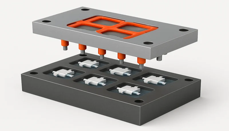
Valve gates use heated probes to control plastic flow, eliminating runners entirely. Each gate has individual control, allowing sequential filling for complex parts or family molds. The technology is mature and reliable when properly maintained, but the initial investment is substantial – $5,000-15,000 per gate depending on size and complexity. Valve gates make sense for high-volume production (100,000+ parts annually) or where runner material cost is significant. Maintenance requirements are real – expect quarterly heating element checks and annual controller calibration.
Thermal Gate Systems
Thermal gates use temperature differences to create controlled separation points. The concept is elegant – heat a section of the runner after filling, creating thermal expansion that breaks the connection. Reality is more complex, requiring precise temperature control and timing. I’ve seen successful applications in packaging and medical devices, but the technology is still evolving. Equipment costs are moderate ($25,000-75,000), but process development time can be extensive.
Investment Justification
The math on self-degating systems is straightforward but often ignored. Calculate your current degating labor cost per part, multiply by annual volume, and compare to the additional tooling investment. Factor in quality improvements, cycle time reduction, and eliminated runner material cost. For most applications, break-even is 25,000-100,000 parts depending on labor rates and part complexity. Don’t forget maintenance costs – self-degating systems require more sophisticated tooling that needs regular servicing.
What Quality Checks Are Needed After Gate Removal?
The four essential post-removal checks are visual inspection, dimensional measurement, surface roughness testing, and stress mark examination.

Visual Inspection Standards
Develop clear visual standards for acceptable gate vestige appearance. Document with photographs showing acceptable, marginal, and reject conditions. Train operators to recognize stress whitening, incomplete cuts, and surface damage. Use consistent lighting – 500-1000 lux at 6500K color temperature reveals defects that might be missed under standard factory lighting. For cosmetic parts, inspect under conditions matching the final use environment – automotive parts under automotive lighting, consumer electronics under typical home lighting.
Dimensional Verification
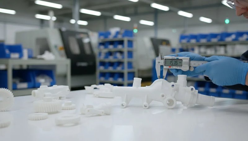
Gate removal can affect part dimensions through stress relief or material removal. Check critical dimensions within 0.1mm of gate locations using calibrated measuring equipment. For thin-wall parts, gate cutting stress can cause immediate dimensional changes or longer-term warpage. Establish dimensional stability by measuring parts immediately after degating, then again after 24-48 hours. Parts that move more than 0.05mm indicate excessive degating stress or poor gate design.
Surface Finish Requirements
Gate vestige surface finish affects both appearance and function. Rough vestiges create stress concentrations and premature failure points. Use surface roughness gauges to establish quantitative standards – typically Ra 1.6-6.3 μm for functional surfaces, Ra 0.4-1.6 μm for cosmetic surfaces. Sand or machine rough vestiges to specification rather than accepting marginal quality. The labor cost of proper finishing is usually less than the cost of field failures or customer complaints.
Common Defects Detection
Train inspectors to recognize stress whitening (indicates overload during cutting), sink marks (material shrinkage around thick gates), color variation (thermal damage from dull cutting tools), and incomplete separation (partial cuts that create stress risers). Use magnification for small gates – 2-4x is usually sufficient to reveal cutting quality. Reject parts with any stress whitening in visible areas or stress concentrations in functional areas. These defects don’t improve with time; they get worse.
“Hot runner systems eliminate all gate removal operations”真
Properly functioning hot runner valve gate systems eliminate physical gates entirely, requiring no degating operations. The plastic flow is controlled by heated probes that seal cleanly when closed.
“Submarine gates always produce better surface finish than edge gates”偽
While submarine gates can produce excellent vestige quality, the surface finish depends on proper tunnel geometry, material selection, and processing parameters. Poorly designed submarine gates can tear irregularly, leaving rough vestiges worse than well-cut edge gates.
Understanding the relationship between gate design and removal efficiency helps engineers make better decisions early in the product development cycle. In practice, the most successful injection molding projects address degating strategy during the initial DFM (Design for Manufacturing) review, well before tool steel is cut. This proactive approach prevents costly mold modifications and production delays that commonly occur when gate removal is treated as an afterthought rather than a design requirement.
“Gate removal method should be determined during mold design phase”真
Gate design directly affects removal difficulty, vestige size, and processing economics. Deciding removal method after tooling is complete often results in suboptimal outcomes and higher production costs.
“Larger gates are always easier to remove cleanly”偽
While larger gates provide more material to grip during cutting, they also require more cutting force and leave larger vestiges. Very large gates can cause stress concentration and cracking during removal, especially in brittle materials.
よくある質問
よくある質問
What is a gate vestige in injection molding?
A gate vestige is the small remaining material stub left on a molded part after the gate is removed. Think of it as the ‘belly button’ where the part was connected to the runner system. Vestige size depends on gate type and removal method – submarine gates leave minimal vestiges (0.05-0.2mm), while direct gates can leave substantial raised areas (2-6mm). The vestige quality affects both part appearance and structural integrity, so proper removal technique is critical for maintaining part specifications.
Can you remove injection molding gates without special tools?
For small gates and low volumes, basic tools like sharp knives or standard nippers can work, but results will be inconsistent and labor-intensive. Edge gates up to 1mm thick can be cut with quality side-cutters, though specialized gate nippers give cleaner results. However, for production volumes above a few hundred parts, the labor cost and quality issues make proper degating tools essential. Trying to save money on tools usually costs more in labor time and rejected parts than investing in appropriate equipment from the start.
ゲート除去は部品の寸法精度に影響しますか?
はい、ゲート除去は誤って行われると寸法精度に影響を与える可能性があります。部品表面に近すぎる切断は、壁から材料を除去し、公差外となる小さすぎる領域を作り出します。逆に、ゲートベスティジを残しすぎると、組み立て適合性を妨げる不要な材料が追加されます。鍵は切断深さの制御です。通常、部品表面の±0.1 mm以内です。厳しい公差部品では、ゲート位置での除去後の寸法チェックが、部品が依然として図面仕様と機能要件を満たしていることを確認するために不可欠です。
自動除去に最適なゲートタイプは何ですか?
潜水(トンネル)ゲートは、追加作業なしで部品射出時にせん断されるように設計されているため、自動除去に理想的です。ゲートはパーティングラインの下をトンネルし、予め決められた弱点で破断し、最小限のベスティジ(典型的には0.05〜0.2mm)を残します。成功は適切なトンネル形状に依存します。長さはゲート径の2〜3倍で、適切な破断角度が必要です。材料選択も重要です。PSなどの脆性材料は、PCなどの粘性材料よりも適しています。ホットランナーシステムでは、バルブゲートが加熱プローブで流れを制御することで除去を完全に排除します。
自動ゲート除去装置のコストはいくらですか?
自動ゲート除去装置のコストは、複雑さとスループット要件によって大きく異なります。低容量操業向けの基本的な空気圧ニッパーステーションは約2,000〜5,000米ドルです。ロボット脱ゲートセルは約50,000米ドルから始まり、統合ビジョンガイダンスを備えた多軸システムでは200,000米ドルを超える場合があります。レーザー切断システムは80,000〜150,000米ドルの範囲です。ROIは人件費削減、スクラップ削減、スループット向上に依存し、年間100,000個以上の生産量では、ほとんどのシステムが12〜24ヶ月以内に投資回収します。
除去が不要なゲート設計はありますか?
はい、いくつかのゲート設計は手動除去を不要にします。ホットランナーバルブゲートは加熱プローブでプラスチック流を制御し、除去すべき物理的なゲートなしにきれいにシールします。潜水ゲートは、適切に設計されていれば、射出時に自動的にせん断されます。一部の熱ゲートシステムは、ランナー接続を切断するために制御加熱を使用します。ただし、これらのシステムは初期工具投資が高く(15〜60%増)、継続的なメンテナンスが必要な場合があります。決定は、生産量、人件費、品質要件に依存します。高容量生産では、脱ゲート作業の排除は通常、追加の工具費用を正当化します。
ゲート除去領域付近の白い応力マークの原因は何ですか?
白い応力マーク(応力白化)は、切断力が材料の降伏強度を超えたときに発生し、分子鎖の配向と光散乱の変化を引き起こします。一般的な原因には、切断ではなく押しつぶすような鈍い切削工具、過剰な切断力、不適切な切断角度、またはガラス転移温度以下の凍結部品の切断が含まれます。PSや硬質PVCなどの脆性材料は特に影響を受けやすいです。予防策には、鋭利な工具の使用、適切な切断技術、切断前に部品を室温まで温めること、およびきれいに切断できる適切な厚さのゲート設計が含まれます。応力白化は永久的であり、通常、目に見える領域では部品の不合格を必要とします。
ゲート除去は単純な二次作業のように思えるかもしれませんが、良い部品が優れた部品になる場所、あるいは優れた部品が台無しになる場所です。鍵は、生産開始後ではなく、金型設計時に脱ゲートを考慮することです。生産量と品質要件に合った適切なゲートタイプを選択し、適切な工具とトレーニングに投資し、明確な品質基準を確立してください。最も安価な脱ゲート方法が、人件費時間、品質問題、顧客満足度を考慮すると、必ずしも最も経済的ではないことを忘れないでください。
ゲート除去プロセスを最適化する準備はできていますか?ZetarMoldでは、初日から脱ゲートを考慮した金型設計をお手伝いします。当社のエンジニアリングチームは、現在のプロセスを評価し、時間を節約し、コストを削減し、品質を向上させる改善策を推奨できます。適切なゲート設計と除去戦略が生産効率をどのように向上させるかについて議論するために、お問い合わせください。