 Przejdź do treści

What Are Injection Molded Ribs and Bosses?
Żebra formowane wtryskowo i kołnierz1Są to główne kategorie lub opcje wyjaśnione w tej sekcji. Aby projektować skuteczne części z tworzyw sztucznych, inżynierowie muszą rozróżniać między wzmocnieniem strukturalnym a elementami montażowymi. Żebra, wypusty, przypory i przejścia ścian mogą wyglądać niepozornie w CAD, ale decydują o sztywności, ryzyku wciągnięcia, wytrzymałości śrub, równowadze chłodzenia i dostępie do formy. Jeśli porównujesz dostawców, użyj tych kontroli z naszym injection molding supplier sourcing guide przed zatwierdzeniem narzędzia. To DFM2 krok pomaga zapobiec późnym zmianom formy.
- Żebra zwiększają sztywność bez dodawania masy; wypusty umożliwiają śruby, wkładki i wyrównanie.
- Obie cechy muszą pozostawać w zakresie 40–60% nominalnej grubości ścianki, aby uniknąć śladów wgnieceń, pustek i odkształceń.
- Samodzielne kołnierze wymagają połączeń żebrami usztywniającymi (żebrami podporowymi), aby rozłożyć obciążenia momentem obrotowym na otaczającą ściankę.
- Dokładny przegląd DFM geometrii żeber i wypustów przed cięciem narzędzia zapobiega kosztownym modyfikacjom formy.
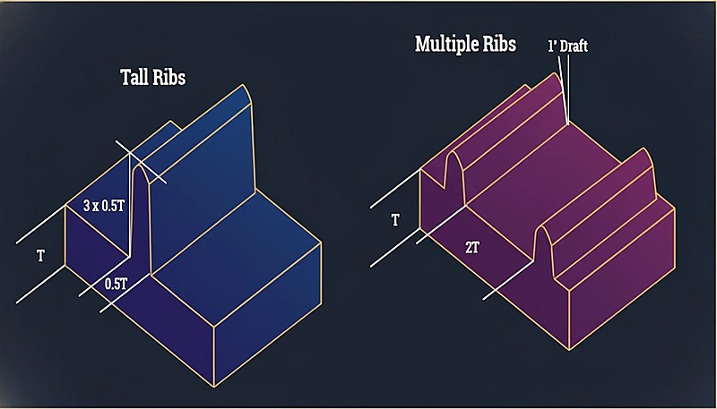
Żebra są cienkimi, podobnymi do ścian występami, które rozciągają się od ściany nominalnej. Ich główną funkcją jest zwiększenie sztywności części bez zwiększania całej grubości ściany. Są przydatne za płaskimi panelami, pokrywami, obudowami i obszarami nośnymi, gdzie część potrzebuje większej sztywności. Dobry projekt żeber kontroluje grubość żebra3, wysokość, odciąg, promień podstawy i odstępy, aby cecha dodawała wytrzymałości bez tworzenia śladów wgnieceń na przeciwległej powierzchni. Dla szerszego kontekstu projektowego, użyj naszego projektowanie form wtryskowych przewodnikiem.
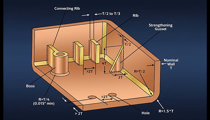
Szefowie są cylindrycznymi występami, zwykle pustymi, zaprojektowanymi do podparcia śrub, wkładek, kołków ustalających lub elementów montażowych. Wypust musi mieć wystarczającą ścianę wokół śruby lub wkładki, jednocześnie unikając nagromadzenia grubego materiału u podstawy. Solidny projekt wypustu często wykorzystuje żebra lub przypory do przenoszenia obciążenia na pobliskie ściany. Zapobiega to pękaniu podczas instalacji śruby i redukuje odkształcenia wokół powierzchni kosmetycznych. Te szczegóły wpływają również na szerszy formowanie wtryskowe proces.
„Wypusty, które nie są połączone ze ścianą boczną, powinny być zawsze wspierane przez przypory (żebra podporowe) u podstawy.”Prawda
Standalone bosses are prone to bending or breaking under torque; gussets distribute the load into the floor of the part and improve material flow.
„Możliwe jest projektowanie bossa o tej samej grubości ścianki jak główna obudowa, aby zapewnić maksymalną siłę utrzymania śruby.”Fałsz
Making boss walls equal to the nominal wall creates a massive thick section at the base, guaranteeing sink marks and voids. Boss walls should be roughly 60% of the nominal wall.
Jak porównują się żebra i kołnierze w kluczowych parametrach projektowych?
Chociaż ich funkcje się różnią, geometryczne zasady dla obu wynikają z jednolitej grubości ściany, stabilnego chłodzenia i przewidywalnego napełniania. Żebra i wypusty powinny być przeglądane razem, ponieważ wypust często potrzebuje wsparcia żeber, a żebro może zmienić lokalny przepływ, chłodzenie i zachowanie wypychania w pobliżu podstawy wypustu.
| Feature Parameter | Rib Design Rules | Boss Design Rules |
|---|---|---|
| Primary Function | Structural Stiffness, Warpage Control | Mechanical Assembly, Alignment |
| Geometry | Linear, Plate-like | Cylindrical (Tubular) |
| Grubość podstawy | 40% – 60% of Nominal Wall (t) | 60% of Nominal Wall (t) |
| Height Constraint | ≤ 3 × Nominal Wall (t) | ≤ 2.5 × Outer Diameter (typical) |
| Kąt zanurzenia | 0.5° – 1.5° per side | 0.5° exterior; 0.25° interior (to grip screws) |
| Spacing | ≥ 2 × Nominal Wall (t) between ribs | ≥ 2 × Nominal Wall (t) from sidewalls |
| Common Defect | Sink Marks (surface depression) | Linie złączy 2 (słabość strukturalna) |
What Are the Advantages and Disadvantages?
Zalety żeber to sztywność, efektywność materiałowa i szybsze chłodzenie, podczas gdy zalety wypustów to mocowanie, pozycjonowanie i wsparcie wkładek. Wadą jest to, że obie cechy tworzą lokalne zmiany grubości, więc słaba geometria może powodować wciągnięcia, uwięziony gaz, pękanie lub dłuższe chłodzenie. Przejrzyj obie cechy razem, ponieważ wypust może potrzebować wsparcia żeber, a żebro może wpłynąć na powierzchnię kosmetyczną lub lokalną ścieżkę przepływu.
Ribs: Structural Reinforcement
| Zalety żeber | Wady żeber |
|---|---|
| Efektywność materiału: Znacznie zwiększa wytrzymałość części przy minimalnym użyciu żywicy w porównaniu do grubych ścian. | Ryzyko kosmetyczne: Połączenie żebra i ścianki jest głównym miejscem występowania wgnieceń na powierzchniach klasy A. |
| Szybkość cyklu: Cienkie żebra szybko stygną, utrzymując krótkie czasy cyklu. | Wentylacja: Głębokie żebra mogą uwięzić gaz (efekt diesla), prowadząc do przypaleń, jeśli nie są odpowiednio wentylowane. |
| Prowadzenie przepływu: Mogą działać jako kanały dopływowe, aby pomóc w napełnianiu cienkich sekcji formy. | Problemy z wypychaniem: Małe nachylenie na żebrach prowadzi do przywierania części w formie lub śladów ciągnięcia. |
Bosses: Assembly Interface
| Zalety wypustów | Wady kołnierzy |
|---|---|
| Umożliwia mocowanie śrubami, wkładki wciskane oraz wyrównanie bez operacji dodatkowych. | Grube sekcje podstawy mogą powodować widoczne wciągnięcia na powierzchniach kosmetycznych. |
| Integruje się bezpośrednio z formą, więc nie wymaga obróbki po formowaniu dla otworów montażowych. | Nieprawidłowa średnica wewnętrzna lub grubość ścianki prowadzi do pękania kołnierza podczas montażu śruby. |
| Mogą być połączone z przypórami i żebrami, aby rozłożyć obciążenia łączników na otaczającą strukturę. | Wymaga starannego odciągu, promieni i rdzenia, aby wyjąć czysto i uniknąć przywierania. |
"Połączenie kołnierza ze ścianką boczną za pomocą cienkiego żebra eliminuje grube przekroje materiału, zachowując stabilność."Prawda
This technique ties the boss to the structure for strength without creating a heavy cross-section that would cause sink marks.
„Blind bosses (bossy, które nie przechodzą przez część) nie wymagają kątów odciągu na średnicy wewnętrznej.”Fałsz
All vertical steel surfaces in injection molding require draft for ejection. A zero-draft core pin creates a vacuum and friction, causing the pin to seize or break during ejection.
When Should You Apply Each Feature?
Żebra są najlepsze dla sztywności bez grubych ścian, podczas gdy kołnierze są najlepsze dla śrub, wkładek, sworzni i wyrównania. Używaj żeber, gdy część potrzebuje odporności na zginanie, płaskości lub rozkładu obciążenia. Używaj kołnierzy, gdy architektura produktu wymaga punktu mocowania lub odniesienia lokalizacyjnego. Gdy obie funkcje nakładają się, łącz kołnierze cienkimi żebrami usztywniającymi zamiast dodawać pełny plastik wokół podstawy.
Application Scenarios for Ribs
Duże płaskie powierzchnie: Używaj żeber, aby zapobiec falowaniu na panelach drzwi samochodowych, obudowach urządzeń i cienkich pokrywach. Kontroluj podstawy żeber, aby powierzchnia kosmetyczna nie wykazywała wgnieceń, przebić lub śladów przepływu. Jest to ważne, gdy zewnętrzna powierzchnia jest teksturowana, malowana lub widoczna dla klienta.
Podłogi nośne: Dodawaj żebra pod tackami, pojemnikami, wspornikami lub paletami tam, gdzie część musi stawiać opór zginaniu. Kierunek żeber powinien podążać ścieżką obciążenia, a nie tylko wypełniać pustą przestrzeń w modelu CAD. Projektanci powinni potwierdzić, że wysokość i odstępy żeber nadal pozwalają na stabilne napełnianie i zwalnianie z formy.
Strefy uderzenia: Umieszczaj żebra za osłonami zderzaków, obudowami ochronnymi i obudowami narzędzi, aby rozproszyć energię uderzenia. Unikaj izolowanych grubych przecięć, ponieważ mogą powodować koncentrację naprężeń i wady formowania. Dla części uderzeniowych, ciągłość żeber, promień i wytrzymałość materiału powinny być analizowane razem.
Korekta odkształcenia: Używaj zrównoważonych wzorów żeber, aby wyrównać sztywność i skurcz chłodzenia. Żebra krzyżowe mogą pomóc, ale projekt nadal wymaga nachylenia, promieni i odstępów, które umożliwiają stabilne napełnianie i wypychanie. Niezrównoważone żebra mogą pogorszyć płaską powierzchnię zamiast ją poprawić.
Application Scenarios for Bosses
PCB mounting: Bosses secure printed circuit boards inside electronic enclosures using self-tapping screws or inserts. The boss height, pilot hole, and support ribs should match screw load, assembly torque, and service life so the board remains stable after repeated use.
Enclosure assembly: Bosses help mate the top and bottom halves of clamshell housings such as controllers, chargers, and remote controls. Good layout keeps screw force away from thin cosmetic walls and leaves enough room for core pins, ejectors, and cooling.
Insert installation: Bosses can hold brass threaded inserts for parts that require repeated disassembly, such as battery compartments or service covers. The boss needs enough material for heat staking or ultrasonic insertion, but excessive thickness can still cause sink and long cooling.
Alignment: Non-threaded bosses or pins help mating parts line up before fastening. This reduces assembly friction and prevents screws from being used as alignment tools, which can crack plastic. Clearance, draft, and tolerance stack-up should be checked with the mating part.
In our Shanghai factory, our engineers with 20+ years of experience use 47 injection molding machines (90T-1850T) to review rib thickness ratios, boss support structures, and sink-mark risk before mold steel is cut. We recommend documenting each rib and boss correction in the DFM report so buyers can compare geometry risk, not just price.
Jak krok po kroku zintegrować żebra i kołnierze?
Rib and boss integration is a staged DFM workflow. First locate every screw, insert, and alignment boss, then dimension each boss from fastener data, place ribs along the bending direction, connect unsupported bosses to walls with gussets, and finally review intersections for sink, draft, venting, ejection, and tool-access risk before steel cutting.
Identify assembly points first.
Determine where screws, inserts, PCB standoffs, or locating pins are needed. Place bosses at those coordinates, then check whether the boss is too close to a corner, shutoff, ejector, or cosmetic wall that could limit cooling or tool access. Mark high-load locations before adding ribs.
Dimension the bosses.
Set the inner diameter from the fastener or insert supplier data, then size the outer diameter and boss wall to avoid cracking and sink. Check screw engagement depth, pilot hole tolerance, draft, and whether the boss needs coring at the base. Confirm the screw torque range before T1.
“Rib and boss intersections need DFM review before tooling.”Prawda
The highest-risk area is often where a boss base, rib root, cosmetic wall, and screw load meet. Checking this intersection before steel cutting reduces sink, cracking, and rework.
“A thicker rib always improves a plastic part.”Fałsz
A thicker rib can increase sink marks, cooling imbalance, and warpage. Multiple moderate ribs with correct draft and spacing are usually safer than one heavy rib.
Determine structural needs second.
Analyze where the part will flex or carry load. Place ribs perpendicular to the bending direction and keep rib root thickness near the material-safe range. Use multiple moderate ribs instead of one thick rib when cosmetic risk is high. Check flow length and gate location at the same time.
Integrate and support with gussets.
A standalone boss is weak. Connect it to the nearest wall or floor using thin gussets or ribs. Avoid filling the full gap with solid plastic because that creates thick sections, slow cooling, and visible sink on the opposite surface. Use rib support only where it improves load transfer.
Manage intersections and mold access.
Where ribs meet bosses or walls, add radii of at least 0.25 times wall thickness when the material and tool design allow it. Confirm draft, venting, polishing access, ejection direction, and whether lifters or slides are required. If you need DFM feedback on rib and boss geometry, request a quote from ZetarMold before tool cutting.
Jakie pytania zadają kupujący dotyczące projektowania żeber i wypustów?
-
boss: A boss is a raised feature commonly used for screws, inserts, fastening, or locating functions in molded parts. ↩
-
DFM: DFM refers to review checks whether a plastic part design can be molded reliably before tooling investment. ↩
-
rib thickness: rib thickness refers to is usually limited as a percentage of nominal wall thickness to reduce sink and uneven cooling. ↩
Często zadawane pytania
Jaka jest różnica między żebrami i wypustami w projektowaniu plastikowym?
Ribs reinforce plastic walls, covers, and floors so a part becomes stiffer without making the entire wall thicker. Bosses support screws, threaded inserts, locating pins, or assembly features. Ribs mainly solve structural stiffness problems, while bosses mainly solve fastening and alignment problems. Both need wall-thickness control because thick rib roots or boss bases can cause sink, voids, warpage, and long cooling cycles. In a good design review, the supplier checks how the two features interact instead of judging each feature alone.
Czy żebra czy wypustki powinny być zaprojektowane jako pierwsze?
Bosses are often placed first when screw locations, insert positions, PCB supports, or assembly constraints are fixed by the product architecture. Ribs are then added to support those bosses, connect load paths, and stiffen nearby surfaces. If the part is mostly structural, rib layout may start earlier. The safest workflow is to define assembly loads, locate bosses, add rib support, then review thickness, draft, radius, and mold access. This order reduces rework when the tooling engineer starts steel design and reviews cooling access.
Jak grube powinny być żebra w porównaniu z główną ścianą?
A practical starting point is to keep rib thickness around 50% to 60% of the nominal wall thickness for many injection molded plastics. Thicker ribs can create sink marks because the rib root cools more slowly than the surrounding wall. The final value depends on resin shrinkage, surface requirements, tool steel condition, and flow length, so DFM should confirm the ratio against the selected material. If the outer face is cosmetic, conservative rib sizing is usually safer for production and later quality approval.
Dlaczego szefowie pękają podczas montażu śrub?
Bosses often crack when the inner diameter is too small, the outer diameter is too thin, the screw creates too much hoop stress, or the boss lacks rib or gusset support. Brittle materials, sharp internal corners, and poor insert installation temperature can make the problem worse. A better design uses the correct pilot hole, enough wall around the screw, rounded transitions, proper draft, and support ribs that spread load. Trial assembly should confirm torque, pull-out strength, and repeatability before approval.
Jak kupujący powinni omawiać projekt żeber i wypustek z dostawcami?
Buyers should ask the supplier to review rib thickness, boss diameter, screw engagement, insert method, sink-mark risk, draft, texture, ejection marks, and mold steel access before tool cutting. They should provide assembly loads, screw type, material grade, tolerance requirements, and cosmetic surface priorities. A capable supplier should return DFM comments explaining which ribs or bosses need adjustment, not just a price quote. This makes supplier capability easier to compare before the order is placed and before steel cost is committed.
Co to jest coring out i dlaczego jest ważne dla bossów?
Coring out means removing unnecessary material from the base of a boss or thick section to reduce the volume of plastic that must cool. This helps prevent sink marks on the opposite cosmetic surface and shortens cycle time. A cored boss still needs enough wall thickness for screw engagement or insert retention, so the core diameter must be calculated relative to the fastener size and material strength. DFM review should verify that the cored geometry still meets pull-out and torque requirements while avoiding sink.


