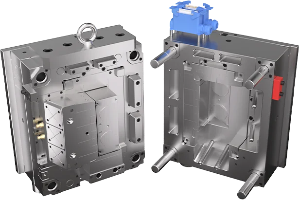
Che cosa sono le nervature e i bossoli stampati a iniezione?
Le nervature e i bossoli1 stampati a iniezione sono le principali categorie illustrate in questa sezione. Per progettare componenti in plastica efficaci, gli ingegneri devono distinguere tra rinforzi strutturali ed elementi di assemblaggio. Nervature, bossoli, fazzoletti di rinforzo e transizioni delle pareti possono sembrare dettagli minori nel CAD, ma determinano rigidezza, rischio di risucchi, tenuta delle viti, equilibrio del raffreddamento e accessibilità dello stampo. Se stai confrontando fornitori, applica questi controlli insieme alla nostra guida alla selezione dei fornitori di stampaggio a iniezione prima di approvare l’attrezzaggio. Questa fase DFM2 aiuta a evitare modifiche tardive allo stampo.
- Le nervature aumentano la rigidità senza aggiungere volume; i pilastri consentono viti, inserti e allineamento.
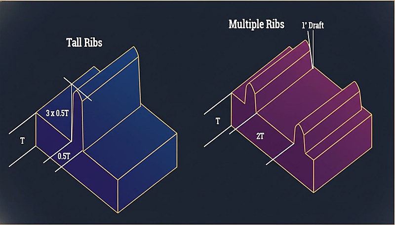
- Entrambi i particolari devono rimanere entro il 40–60% dello spessore nominale della parete per evitare segni di ritiro, cavità e deformazioni.
- I rinforzi isolati necessitano di connessioni a contrafforte (nervatura di supporto) per distribuire i carichi di torsione sulla parete circostante.
- Una revisione DFM approfondita della geometria di nervature e perni prima del taglio dello stampo previene costose modifiche allo stampo.
Le nervature sono sporgenze sottili, simili a pareti, che si estendono dalla parete nominale. La loro funzione principale è aumentare la rigidezza del pezzo senza incrementare lo spessore dell’intera parete. Sono utili dietro pannelli piani, coperchi, alloggiamenti e zone portanti in cui serve maggiore rigidità. Una buona progettazione controlla lo spessore delle nervature3, l’altezza, lo sformo, il raggio alla radice e la spaziatura, così da aumentare la resistenza senza creare segni di risucchio sulla superficie opposta. Per un contesto progettuale più ampio, consulta la nostra guida alla progettazione degli stampi a iniezione.
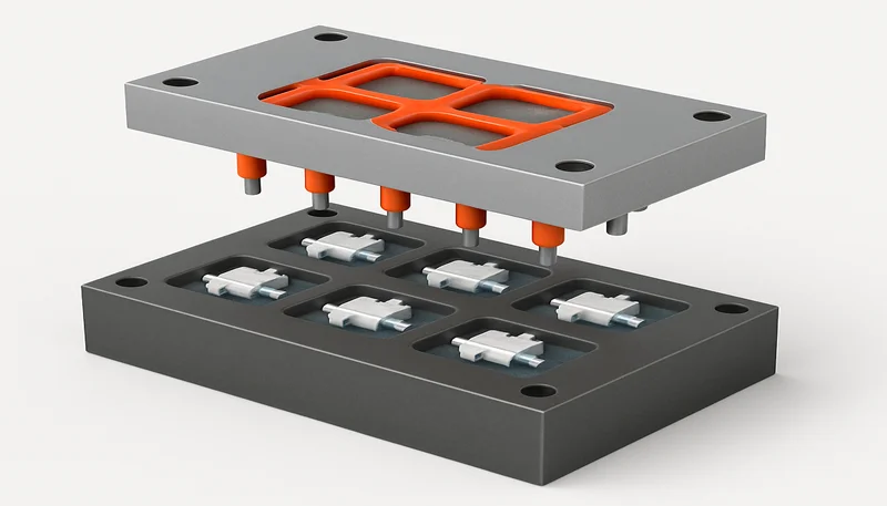
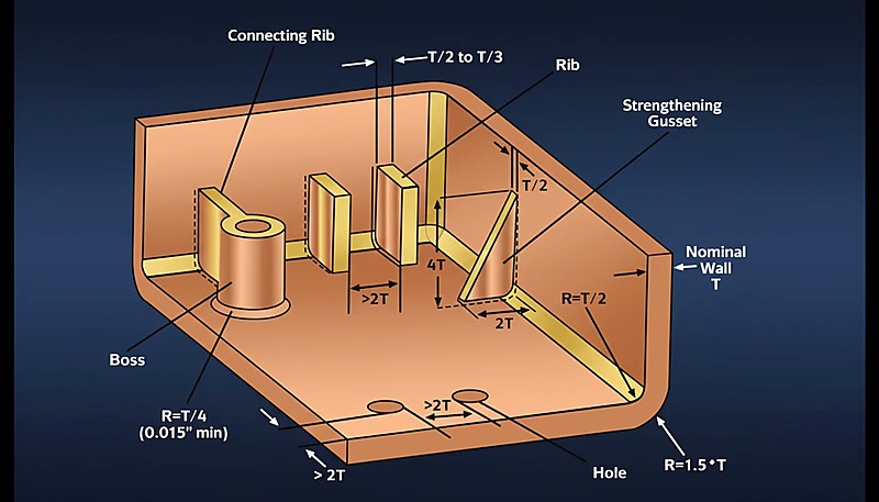
I bossoli sono sporgenze cilindriche, solitamente cave, progettate per sostenere viti, inserti, perni di posizionamento o elementi di assemblaggio. Un bossolo deve avere materiale sufficiente attorno alla vite o all’inserto, evitando al contempo accumuli eccessivi alla base. Un bossolo robusto utilizza spesso nervature o fazzoletti di rinforzo per trasferire il carico alle pareti vicine. Ciò previene cricche durante l’installazione delle viti e riduce la deformazione attorno alle superfici estetiche. Questi dettagli influiscono anche sul più ampio processo di stampaggio a iniezione.
"I bossoli non collegati alla parete laterale devono essere sempre sostenuti alla base da fazzoletti (nervature di supporto)."True
Le colonnine isolate tendono a piegarsi o rompersi sotto torsione; i fazzoletti distribuiscono il carico sul fondo del pezzo e migliorano il flusso del materiale.
"È accettabile progettare un bossolo con lo stesso spessore di parete dell'alloggiamento principale per garantire la massima tenuta della vite."False
Rendere le pareti dei bossaggi uguali alla parete nominale crea una sezione molto spessa alla base, garantendo la comparsa di risucchi e vuoti. Le pareti dei bossaggi dovrebbero essere pari a circa il 60% della parete nominale.
Come si Confrontano Nervature e Pioli nei Parametri di Progetto Chiave?
Sebbene le loro funzioni differiscano, le regole geometriche per entrambi derivano da uno spessore uniforme della parete, un raffreddamento stabile e un riempimento prevedibile. Nervature e perni dovrebbero essere esaminati insieme perché un perno spesso necessita del supporto di nervature e una nervatura può alterare il flusso locale, il raffreddamento e il comportamento di estrazione vicino alla base del perno.
| Parametro della caratteristica | Regole di progettazione delle nervature | Regole di progettazione dei bossoli |
|---|---|---|
| Funzione principale | Rigidità strutturale, controllo della deformazione | Assemblaggio meccanico, allineamento |
| Geometria | Lineare, simile a una piastra | Cilindrico (tubolare) |
| Spessore della base | 40–60% della parete nominale (t) | 60% della parete nominale (t) |
| Vincolo di altezza | ≤ 3 × parete nominale (t) | ≤ 2,5 × diametro esterno (tipico) |
| Angolo di sformo | 0.5° – 1.5° per lato | 0,5° all'esterno; 0,25° all'interno (per trattenere le viti) |
| Distanza | ≥ 2 × parete nominale (t) tra le nervature | ≥ 2 × parete nominale (t) dalle pareti laterali |
| Difetto comune | Risucchi (depressione superficiale) | Linee di Saldatura 2 (debolezza strutturale) |
Quali sono i vantaggi e gli svantaggi?
I vantaggi delle nervature sono rigidità, efficienza dei materiali e raffreddamento più rapido, mentre i vantaggi dei pilastri sono fissaggio, posizionamento e supporto per inserti. Lo svantaggio è che entrambe le caratteristiche creano cambiamenti locali di spessore, quindi una geometria scadente può causare infossamenti, gas intrappolati, crepe o raffreddamento più lungo. Rivedi le due caratteristiche insieme, perché un pilastro potrebbe aver bisogno del supporto di una nervatura e una nervatura potrebbe influire sulla superficie estetica o sul percorso di flusso locale.
Nervature: rinforzo strutturale
| Vantaggi delle Nervature | Svantaggi delle Nervature |
|---|---|
| Efficienza dei materiali: Aumenta significativamente la resistenza della parte con un uso minimo di resina rispetto a pareti spesse. | Rischio Estetico: L'intersezione tra nervatura e parete è un punto critico per gli avvallamenti sulle superfici di Classe A. |
| Velocità di Ciclo: Le nervature sottili si raffreddano rapidamente, mantenendo bassi i tempi di ciclo. | Sfogo: Nervature profonde possono intrappolare gas (effetto diesel), portando a bruciature se non sfogate correttamente. |
| Guida del flusso: Possono fungere da canali di flusso per aiutare a riempire sezioni sottili dello stampo. | Problemi di sformo: Uno sformo insufficiente sulle nervature porta all'adesione delle parti nello stampo o a segni di trascinamento. |
Bossoli: interfaccia di assemblaggio
| Vantaggi dei Pioli | Svantaggi dei pilastri |
|---|---|
| Consente il fissaggio con viti, inserti a pressione e allineamento senza operazioni secondarie. | Le sezioni di base spesse possono causare segni di ritiro visibili sulle superfici estetiche. |
| Si integra direttamente nello stampo, quindi non è necessaria lavorazione post-stampaggio per i fori di assemblaggio. | Un ID o uno spessore di parete errati portano alla rottura del rinforzo durante l'installazione della vite. |
| Può essere combinato con rinforzi e nervature per distribuire i carichi dei fissaggi nella struttura circostante. | Richiede attenzione alla sformo, ai raggi e alla svuotatura per uno sformo pulito ed evitare l'adesione. |
"Collegare un boss a una parete laterale mediante una nervatura sottile elimina le sezioni di materiale spesse mantenendo la stabilità."True
Questa tecnica collega il bossolo alla struttura per conferirgli resistenza senza creare una sezione massiccia che causerebbe risucchi.
"I bossoli ciechi (che non attraversano il pezzo) non richiedono angoli di sformo sul diametro interno."False
Tutte le superfici verticali in acciaio nello stampaggio a iniezione richiedono uno sformo per l'espulsione. Un perno anima senza sformo crea vuoto e attrito, facendo grippare o rompere il perno durante l'espulsione.
Quando si deve applicare ciascuna caratteristica?
Le nervature sono ideali per la rigidità senza pareti spesse, mentre i pilastri sono ideali per viti, inserti, perni e allineamento. Usa le nervature quando la parte necessita di resistenza alla flessione, planarità o distribuzione del carico. Usa i pilastri quando l’architettura del prodotto richiede un punto di fissaggio o un dato di riferimento. Quando entrambe le funzioni si sovrappongono, collega i pilastri con rinforzi sottili invece di aggiungere plastica solida attorno alla base.
Scenari applicativi delle nervature
Grandi superfici piane: usare nervature per prevenire l’effetto di instabilità «oil canning» su pannelli di portiere automobilistiche, alloggiamenti di elettrodomestici e coperture sottili. Controllare lo spessore alla base delle nervature affinché sulla superficie estetica non compaiano risucchi, trasparenze o esitazioni del flusso. Ciò è importante quando la superficie esterna è goffrata, verniciata o visibile al cliente.
Piani portanti: aggiungere nervature sotto vassoi, contenitori, staffe o pallet nei punti in cui il pezzo deve resistere alla flessione. La direzione delle nervature deve seguire il percorso del carico, non limitarsi a riempire gli spazi vuoti del modello CAD. I progettisti devono verificare che altezza e spaziatura consentano comunque un riempimento stabile e il corretto distacco dallo stampo.
Zone d’impatto: collocare nervature dietro i rivestimenti dei paraurti, le custodie protettive e gli alloggiamenti degli utensili per distribuire l’energia d’urto. Evitare intersezioni spesse isolate, perché possono creare concentrazioni di tensione e difetti di stampaggio. Nei pezzi soggetti a impatto, continuità delle nervature, raggi e tenacità del materiale devono essere valutati insieme.
Correzione dello svergolamento: usare configurazioni bilanciate di nervature per uniformare la rigidezza e il ritiro durante il raffreddamento. Le nervature incrociate possono essere d’aiuto, ma il progetto richiede comunque sformo, raggi e spaziatura che consentano riempimento ed espulsione stabili. Nervature sbilanciate possono peggiorare una superficie piana invece di migliorarla.
Scenari applicativi delle colonnine
Montaggio di PCB: i bossoli fissano i circuiti stampati all’interno degli involucri elettronici mediante viti autofilettanti o inserti. Altezza del bossolo, foro pilota e nervature di supporto devono essere adeguati al carico della vite, alla coppia di assemblaggio e alla vita utile, affinché la scheda rimanga stabile anche dopo un uso ripetuto.
Assemblaggio degli involucri: i bossoli aiutano ad accoppiare le metà superiore e inferiore degli involucri a conchiglia, come quelli di controller, caricabatterie e telecomandi. Una buona disposizione mantiene la forza delle viti lontana dalle sottili pareti estetiche e lascia spazio sufficiente per perni d’anima, espulsori e raffreddamento.
Installazione degli inserti: i bossoli possono ospitare inserti filettati in ottone nei pezzi che richiedono smontaggi ripetuti, come vani batteria o coperture di servizio. Il bossolo deve contenere materiale sufficiente per l’inserimento a caldo o a ultrasuoni, ma uno spessore eccessivo può comunque causare risucchi e lunghi tempi di raffreddamento.
Allineamento: bossoli o perni non filettati aiutano ad allineare i componenti accoppiati prima del fissaggio. Ciò riduce l’attrito durante l’assemblaggio e impedisce di usare le viti come strumenti di allineamento, evitando cricche nella plastica. Gioco, sformo e accumulo delle tolleranze devono essere verificati insieme al componente accoppiato.
Nella nostra fabbrica di Shanghai, i nostri ingegneri con oltre 20 anni di esperienza utilizzano 47 macchine per stampaggio a iniezione (da 90T a 1850T) per rivedere i rapporti di spessore delle nervature, le strutture di supporto delle boccole e il rischio di avvallamenti prima che l'acciaio dello stampo venga tagliato. Raccomandiamo di documentare ogni correzione di nervatura e boccola nel rapporto DFM in modo che gli acquirenti possano confrontare il rischio geometrico, non solo il prezzo.
Come Integrare Nervature e Rinforzi Passo dopo Passo?
L’integrazione di nervature e boccole è un flusso di lavoro DFM a fasi. Prima individuare ogni vite, inserto e boccola di allineamento, poi dimensionare ogni boccola dai dati del fissaggio, posizionare le nervature lungo la direzione di flessione, collegare le boccole non supportate alle pareti con contrafforti, e infine rivedere le intersezioni per rischio di avvallamenti, sformo, sfogo, espulsione e accesso allo strumento prima del taglio dell’acciaio.
Individuare innanzitutto i punti di assemblaggio. Determinare dove sono necessari viti, inserti, distanziali per PCB o perni di posizionamento. Collocare i bossoli in corrispondenza di tali coordinate, quindi verificare che non siano troppo vicini a un angolo, una chiusura, un espulsore o una parete estetica che possa limitare il raffreddamento o l’accesso dell’utensile. Contrassegnare i punti sottoposti a carichi elevati prima di aggiungere le nervature.
Dimensionare i bossoli. Impostare il diametro interno in base ai dati del fornitore della vite o dell’inserto, quindi dimensionare il diametro esterno e la parete del bossolo per evitare cricche e risucchi. Verificare la profondità di presa della vite, la tolleranza del foro pilota, lo sformo e l’eventuale necessità di svuotare la base del bossolo. Confermare l’intervallo di coppia della vite prima del T1.
"Le intersezioni tra nervature e bossaggi richiedono una revisione DFM prima della costruzione dello stampo."True
L'area a più alto rischio è spesso dove si incontrano la base di una boccola, la radice di una nervatura, una parete estetica e il carico della vite. Verificare questa intersezione prima del taglio dell'acciaio riduce avvallamenti, crepe e rilavorazioni.
"Una nervatura più spessa migliora sempre un pezzo in plastica."False
Una nervatura più spessa può aumentare i segni di affossamento, lo squilibrio di raffreddamento e la deformazione. Nervature multiple moderate con sformo e spaziatura corretti sono generalmente più sicure di una nervatura pesante.
Determinare in secondo luogo le esigenze strutturali. Analizzare dove il pezzo si fletterà o sopporterà un carico. Disporre le nervature perpendicolarmente alla direzione di flessione e mantenere lo spessore alla radice nell’intervallo sicuro per il materiale. Quando il rischio estetico è elevato, usare più nervature di dimensioni moderate invece di una sola nervatura spessa. Verificare contemporaneamente la lunghezza del flusso e la posizione del punto di iniezione.
Integrare e sostenere con fazzoletti di rinforzo. Un bossolo isolato è debole. Collegarlo alla parete o al piano più vicino mediante fazzoletti o nervature sottili. Evitare di riempire l’intero spazio con plastica piena, perché si creerebbero sezioni spesse, raffreddamento lento e risucchi visibili sulla superficie opposta. Usare il supporto delle nervature solo dove migliora il trasferimento del carico.
Gestire le intersezioni e l’accesso allo stampo. Nei punti in cui le nervature incontrano bossoli o pareti, aggiungere raggi pari ad almeno 0,25 volte lo spessore della parete, quando il materiale e il progetto dello stampo lo consentono. Verificare sformo, sfiato, accesso per la lucidatura, direzione di espulsione e l’eventuale necessità di sollevatori o carrelli. Se ti serve un riscontro DFM sulla geometria di nervature e bossoli, richiedi un preventivo a ZetarMold prima di lavorare lo stampo.
Quali Domande Fanno gli Acquirenti sulla Progettazione di Nervature e Pioli?
bossolo: elemento sporgente comunemente usato nei pezzi stampati per viti, inserti, fissaggio o posizionamento. ↩
DFM: insieme di verifiche volte a stabilire se il progetto di un pezzo in plastica può essere stampato in modo affidabile prima di investire nell'attrezzaggio. ↩
spessore delle nervature: viene solitamente limitato a una percentuale dello spessore nominale della parete per ridurre risucchi e raffreddamento non uniforme. ↩
Domande frequenti
Qual è la differenza tra nervature e rinforzi nella progettazione della plastica?
Le nervature rinforzano pareti, coperchi e fondi in plastica in modo che un componente diventi più rigido senza rendere l’intera parete più spessa. Le boccole supportano viti, inserti filettati, perni di posizionamento o caratteristiche di assemblaggio. Le nervature risolvono principalmente problemi di rigidità strutturale, mentre le boccole risolvono principalmente problemi di fissaggio e allineamento. Entrambe richiedono il controllo dello spessore della parete perché radici di nervature spesse o basi di boccole possono causare avvallamenti, vuoti, deformazioni e lunghi cicli di raffreddamento. In una buona revisione del design, il fornitore verifica come le due caratteristiche interagiscono invece di giudicare ciascuna caratteristica separatamente.
Le costole o i rinforzi devono essere progettati per primi?
I perni sono spesso posizionati per primi quando le posizioni delle viti, le posizioni degli inserti, i supporti del PCB o i vincoli di assemblaggio sono fissati dall’architettura del prodotto. Le nervature vengono quindi aggiunte per supportare quei perni, collegare i percorsi di carico e irrigidire le superfici vicine. Se la parte è principalmente strutturale, il layout delle nervature può iniziare prima. Il flusso di lavoro più sicuro è definire i carichi di assemblaggio, posizionare i perni, aggiungere il supporto a nervatura, quindi rivedere spessore, sformo, raggio e accesso allo stampo. Questo ordine riduce il lavoro di rielaborazione quando il progettista dello stampo inizia il design dell’acciaio e rivede l’accesso al raffreddamento.
Quanto spesse dovrebbero essere le nervature rispetto alla parete principale?
Un punto di partenza pratico è mantenere lo spessore della nervatura intorno al 50% - 60% dello spessore nominale della parete per molte materie plastiche stampate a iniezione. Nervature più spesse possono creare segni di affossamento perché la radice della nervatura si raffredda più lentamente della parete circostante. Il valore finale dipende dal ritiro della resina, dai requisiti superficiali, dalle condizioni dell’acciaio dello stampo e dalla lunghezza di flusso, quindi il DFM dovrebbe confermare il rapporto rispetto al materiale selezionato. Se la superficie esterna è estetica, dimensioni conservative delle nervature sono generalmente più sicure per la produzione e l’approvazione qualitativa successiva.
Perché i boss si rompono durante l’installazione delle viti?
Le boccole spesso si crepano quando il diametro interno è troppo piccolo, il diametro esterno è troppo sottile, la vite crea troppa tensione circonferenziale o la boccola manca di supporto da nervature o contrafforti. Materiali fragili, angoli interni acuti e una temperatura di installazione dell’inserto inadeguata possono peggiorare il problema. Un design migliore utilizza il foro pilota corretto, parete sufficiente attorno alla vite, transizioni arrotondate, sformo adeguato e nervature di supporto che distribuiscono il carico. L’assemblaggio di prova dovrebbe confermare coppia, resistenza allo strappo e ripetibilità prima dell’approvazione.
Come dovrebbero i compratori rivedere il design di costole e boss con i fornitori?
Gli acquirenti dovrebbero chiedere al fornitore di rivedere lo spessore delle nervature, il diametro dei perni, l’innesto delle viti, il metodo di inserimento, il rischio di affossamento, lo sformo, la texture, i segni di espulsione e l’accesso all’acciaio dello stampo prima del taglio dello stampo. Dovrebbero fornire i carichi di assemblaggio, il tipo di vite, il grado del materiale, i requisiti di tolleranza e le priorità delle superfici estetiche. Un fornitore competente dovrebbe restituire commenti DFM che spiegano quali nervature o perni necessitano di aggiustamenti, non solo un preventivo di prezzo. Questo rende più facile confrontare le capacità dei fornitori prima di effettuare l’ordine e prima di impegnare il costo dell’acciaio.
Cos’è il coring out e perché è importante per i capi?
Svuotare significa rimuovere materiale non necessario dalla base di un perno o di una sezione spessa per ridurre il volume di plastica che deve raffreddarsi. Questo aiuta a prevenire segni di affossamento sulla superficie estetica opposta e riduce il tempo di ciclo. Un perno svuotato ha comunque bisogno di uno spessore di parete sufficiente per l’innesto della vite o la ritenzione dell’inserto, quindi il diametro del nucleo deve essere calcolato in relazione alle dimensioni del fissaggio e alla resistenza del materiale. La revisione DFM dovrebbe verificare che la geometria svuotata soddisfi ancora i requisiti di estrazione e torsione evitando l’affossamento.