 Overslaan naar inhoud

Spuitgieten is een cyclisch proces — elk onderdeel wordt geboren uit een zich herhalende reeks van injectie, persen, koelen en uitwerpen. De totale tijd voor één complete lus is de Cyclustijd1, en het bepaalt direct uw productiesnelheid en kosten per onderdeel. In onze fabriek in Shanghai hebben we meer dan 20 jaar besteed aan het finetunen van cyclustijden over duizenden matrijzen. Deze gids ontleedt de berekeningsmethode zodat u cyclustijd voor uw eigen projecten kunt schatten, meten en optimaliseren.
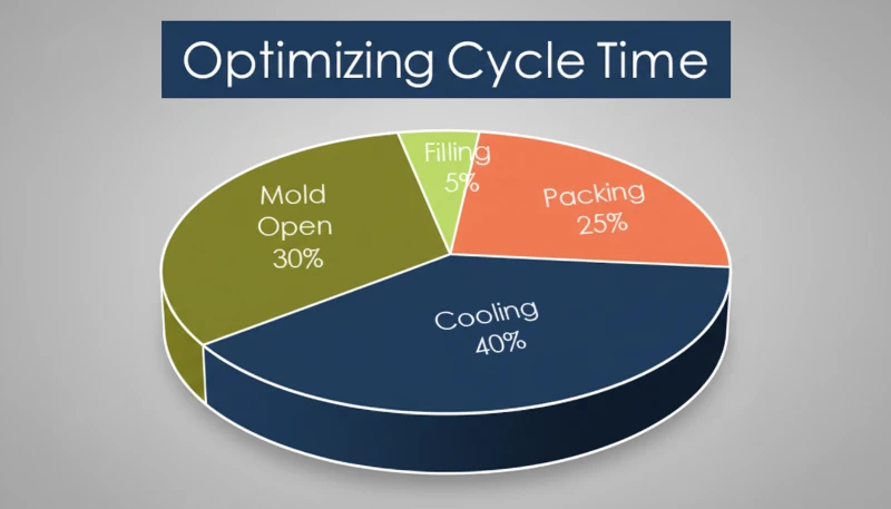
- Cyclus tijd = injectie + pakken + koeling + ejectie + matrijs open/sluiten
- Koelen beslaat typisch 60–70% van de totale cyclusduur
- Wanddikte is de allerbelangrijkste drijver van koelduur
- Een verkorting van 1 seconde kan op een mat met meerdere holtes leiden tot meer dan 100.000 extra onderdelen per jaar
- Een goed ontwerp voor matkoeling is de meest kosteneffectieve optimalisatie
Wat is Cyclustijd bij Spuitgieten?
Cyclustijd is de totale verstreken tijd vanaf het begin van de ene injectieshot tot het begin van de volgende. Het meet hoe snel uw machine onderdelen kan produceren — en het is de allerbelangrijkste maatstaf voor spuitgietvormom de productiviteit te verhogen.
Bekijk het zo: als je een mat met 4 holtes gebruikt en een cyclus van 30 seconden, dan produceer je ongeveer 480 onderdelen per uur. Verkort dit tot 25 seconden, en je springt naar 576 – een productiestijging van 20% zonder extra kapitaalinvestering. Daarom zijn ervaren ingenieurs geobsedeerd door elke seconde.
De formule is in concept eenvoudig: t_cyclus = t_injectie + t_pers + t_koel + t_open + t_uitwerp + t_sluit. In de praktijk overlappen sommige fasen. Schroefterugwinning2 (het plastificeren van de volgende shot) vindt plaats tijdens het koelen, dus je neemt de langste van t_koel en t_schroefherstel in plaats van beide op te tellen.
Cyclus tijd is geen vaststaande eigenschap — het verandert met materiaal, onderdeel geometrie, matrijs ontwerp, en machine instellingen. Een dunwandige PP dop kan cycleren in 5–8 seconden, terwijl een dikwandige polycarbonaat behuizing 60 seconden of meer kan nemen. Ingenieurs spreken vaak over 'optimale cyclus tijd' — de snelste herhaalbare cyclus die nog onderdelen produceert die alle kwaliteitsspecificaties halen. Te snel gaan geeft kortgeschoten onderdelen, zinkmarkeringen, of dimensionale drift. Te langzaam gaan, en je verspilt geld op machine tijd.
Hoe bereken je stap voor stap de cyclusduur?
De formule voor cyclusduur is de som van de injectie-, naspuit-, koel- en matbewerkingstijden. Sommige fasen overlappen – bijvoorbeeld vindt schroefterugwinning plaats tijdens het koelen – dus je neemt de langste duur in plaats van beide op te tellen.
Injectie Tijd (t_inject)
Dit is de tijd die nodig is om de holte te vullen met gesmolten plastic. Voor de meeste onderdelen is dit 0,5–5 seconden. Je kunt het berekenen als: t_inject = Onderdeelgewicht (g) ÷ Injectiesnelheid (g/s). Bijvoorbeeld, een onderdeel van 50g op een machine die 100 g/s levert, neemt ongeveer 0,5 seconden om te vullen. Maar realistische injectieprofielen gebruiken multi-staps snelheden (langzaam-snel-langzaam), dus de werkelijke tijd is iets langer dan het theoretische minimum.
Pakken/Houd Tijd (t_pack)
Nadat de holte gevuld is, houdt u druk vast om materiaalkrimp te compenseren. Dit duurt typisch 1–10 seconden, afhankelijk van wanddikte en poortbevriestijd. Dunne onderdelen bevriezen snel; dikke onderdelen hebben een langere houdtijd nodig. De persfase eindigt wanneer de poort stolt en de holte afsluit.
Koeltijd (t_koel)
Dit is waar het grootste deel van uw cyclus zich bevindt. Voor semi-kristallijne materialen, Koeltijd3 is ongeveer evenredig met het kwadraat van de wanddikte: t_koel ≈ C × (wanddikte)², waarbij C afhangt van de thermische diffusiviteit van het materiaal en het temperatuurverschil tussen smelt en mat. Voor een wand van 3 mm in ABS, verwacht 15–25 seconden. Voor een wand van 5 mm, springt dit naar 40–60 seconden.
Matrijs Openen/Sluiten en Uitwerpen
Matrijs openen en sluiten duurt typisch 2–10 seconden, afhankelijk van matrijsgrootte en pers tonnage. Kleine matrijzen op 80–200T persen doen 2–4 seconden; grote matrijzen op 500–1000T persen nemen 6–12 seconden. Uitwerptijd voegt 0.5–3 seconden toe, waarbij geautomatiseerde pickers sneller zijn dan handmatige verwijdering.
Alles Samenbrengen
Hier is een voorbeeldberekening voor een middelgrote ABS-behuizing (3mm wand, 80g, 4-holte matrijs op een 200T pers): t_injectie ≈ 1.5s, t_pers ≈ 3s, t_koel ≈ 20s, t_open + t_uitwerp + t_sluit ≈ 5s. Totale cyclustijd: ongeveer 29.5 seconden. In productie hebben we cycli gezien variërend van 5 seconden voor dunwandige verpakking tot meer dan 90 seconden voor dikke technische onderdelen.
Wat zijn de vier fasen van een spuitgietcyclus?
De vier fasen zijn injectie (vullen), persen (houden), koelen en uitwerpen/herstellen. Elk heeft een duidelijke rol in onderdeelkwaliteit en cyclus efficiëntie.
Fase 1 — Injectie (Vullen)
De schroef duwt naar voren en perst gesmolten plastic door de runner en de ingang in de holte. Snelheid is cruciaal – te langzaam en de smelt stolt voor het vullen; te snel en je krijgt straalvorming of uitsteeksels. Injectietijd is typisch de kortste fase, maar legt de basis voor de onderdeelkwaliteit.
Fase 2 – Naspuiten (Nadrukken)
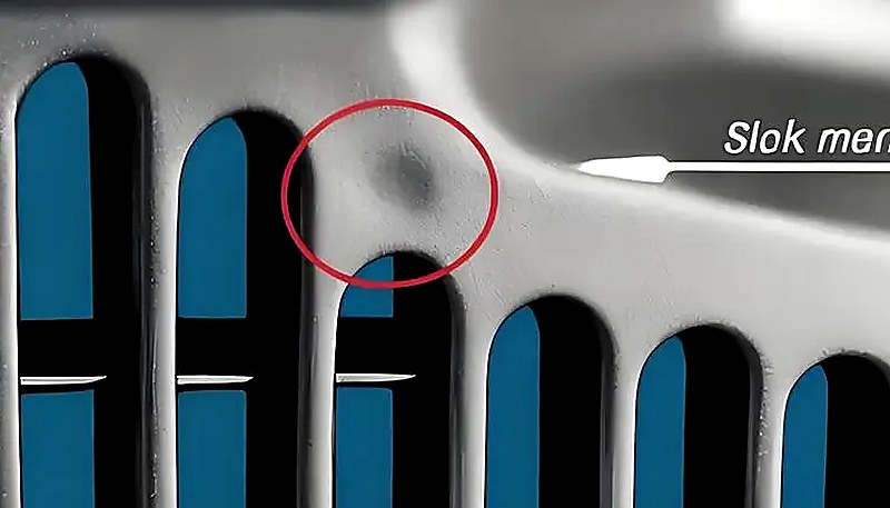
Zodra de holte volumetrisch vol is, schakelt de machine over op houddruk. Deze extra druk perst extra materiaal in om thermische krimp te compenseren terwijl het onderdeel afkoelt. Het persen gaat door totdat de poort bevriest en de holte afsluit. Een verkeerde persduur is een veelvoorkomende oorzaak van zinkplekken en holtes.
Fase 3 — Koeling
De matrijs houdt een gecontroleerde temperatuur (meestal 20–80°C afhankelijk van het materiaal), en trekt warmte uit het onderdeel totdat het stevig genoeg is om zonder vervorming uit te stoten. Deze fase duurt het langst — vaak 60–70% van de totale cyclus tijd. Tegelijkertijd trekt de spindel terug en plasticiseert de volgende injectie, dus koeling en spindelherstel overlappen.
Fase 4 – Uitwerpen en Resetten
De mat opent, het onderdeel wordt uitgeworpen (mechanisch of door een robot), en de mat sluit voor het volgende schot. Uitwerpen kan een knelpunt zijn als onderdelen blijven plakken of als handmatige inspectie nodig is. Goed ontworpen uitwerpsystemen en juiste ontluikingshoeken houden deze fase voorspelbaar.
In onze fabriek in Shanghai hebben we 47 spuitgietmachines van 90T tot 1850T. Met meer dan 20 jaar productie-ervaring met meer dan 400 materialen, hebben we cyclustijden geoptimaliseerd van snel-cyclisch PP-verpakkingsonderdelen van 8 seconden tot dikwandige PC-componenten van 60+ seconden. Elke machine registreert cyclusgegevens shot voor shot voor continue verbetering.
Waarom domineert de koeltijd de cyclus?
Koelen is de dominante fase, die 60–70% van de totale cyclusduur in beslag neemt omdat warmteafvoer uit dikke polymeerwanden langer duurt dan elke andere stap.
De polymeersmelt komt de holte binnen bij 200–300°C, en je moet deze afkoelen tot 40–80°C voordat het veilig uit te werpen is. De warmteoverdrachtsnelheid hangt af van verschillende factoren.
Wanddikte — De Grote Factor
Koeltijd schaalt ongeveer met het kwadraat van de dikste sectie. Een onderdeel van 4mm dik heeft ongeveer 1.8× de koeltijd nodig van een onderdeel van 3mm. Daarom dringen DFM-beoordelingen altijd aan op minimale uniforme wanddikte.
Materiaal Thermische Geleidbaarheid
Amorfe materialen zoals PC en ABS koelen anders af dan semi-kristallijne zoals PA en POM. Kristallijne materialen geven latente warmte vrij tijdens stolling, wat de koeltijd verlengt. Materiaalkeuze gaat niet alleen over onderdeelprestaties – het heeft directe invloed op de productie-economie.
Mattemperatuur en ontwerp van koelkanalen
Een lagere matrijs temperatuur onttrekt sneller warmte, maar te koud veroorzaakt restspanning, vervorming of een slechte oppervlakteafwerking. Goed geplaatste bafflecircuits, warmtepijpen of conforme koelkanalen kunnen de koeltijd met 20–40% verkorten in vergelijking met eenvoudige geboorde kanalen. Dit is waar matrijsengineering zich terugverdient.

De praktische implicatie: als u de cyclustijd wilt verminderen, richt u dan eerst op de koeling. Uniforme wanddikte (houd variaties onder 25%), geoptimaliseerde koelkanaalindeling en juiste waterstroomsnelheden geven het grootste rendement.
Welke factoren hebben de grootste invloed op de cyclusduur?
De grootste factoren zijn wanddikte, thermische materiaaleigenschappen, ontwerp van matrijskoeling en machinecapaciteit – ruwweg in die volgorde.
De onderdeelgeometrie is de belangrijkste factor. Dikkere wanden betekenen exponentieel langere koeling. Complexe onderdeelgeometrieën met diepe ribben, penpunten of variërende diktesecties creëren hotspots die u dwingen de hele cyclus te verlengen voor het langzaamst koelende gebied.
Materiaalkeuze is belangrijk omdat verschillende polymeren verschillende thermische eigenschappen hebben. PP en PE koelen relatief snel. PC, PPSU en versterkte nylons hebben meer tijd nodig. Als cyclustijd kritisch is en de prestaties het toelaten, kan overschakelen van PC naar ABS de koeling met 30–40% verminderen.
Matrijzenontwerp is waar je wint of verliest. Belangrijke factoren zijn onder meer de plaatsing en stroomsnelheid van koelkanalen, het type en de locatie van de ingang, de betrouwbaarheid van het uitstootsysteem en de keuze van het matrijzenmateriaal. Berylliumkoper inzetstukken geleiden warmte 3–5× sneller dan staal en zijn uitstekend voor hotspotgebieden. Machine-instellingen geven je incrementele winst — hogere inspuitsnelheid, geoptimaliseerde houdprofielen en snellere matrijsopenings- en sluitsnelheden helpen allemaal, maar dit is fijn afstellen in vergelijking met ontwerp en matrijstechniek.
"Koeltijd neemt typisch 60–70% van de totale spuitgietcyclusduur in beslag."Echt
Correct. In duizenden productieruns in onze fabriek is koeling consequent de dominante fase in de cyclus. Zelfs bij snelcyclende verpakkingsmatrijzen blijft koeling de langste enkele fase.
"Het verhogen van de inspuitsnelheid vermindert altijd de totale cyclusduur."Vals
Onjuist. Na een optimaal punt veroorzaakt snellere inspuiting uitstulpingen, straalvorming of luchtinsluitingen die langere naspuit- en koeltijd vereisen om te verhelpen. De netto cyclusduur kan zelfs toenemen als u de inspuitsnelheid te ver doorvoert.
Hoe Kunt U de Cyclusduur Optimaliseren Zonder In Te Leveren op Kwaliteit?
Richt u eerst op koelingoptimalisatie, dan op wanddiktereductie en vervolgens op machineafstelling – in die volgorde van impact. Hier zijn de meest effectieve strategieën die wij in productie toepassen.
Koelkanalen herontwerpen
Dit is de verandering met het hoogste rendement op investering. Als uw matrijs eenvoudige recht geboorde kanalen heeft, kan overschakelen naar baffles, bubblers of spiraalkanalen de koeltijd met 15–30% verminderen. Voor hoogvolumematrijzen kan conforme koeling (mogelijk gemaakt door metaal 3D-printen) reducties van 40% of meer bereiken.
Minimaliseer en uniformeer wanddikte
Elke reductie van 0,5 mm in de maximale wanddikte kan de koeltijd met 10–20% verkorten. Houd de variatie in wanddikte onder 25% over het gehele onderdeel. Werk vroeg samen met uw ontwerpteam — DFM-aanpassingen zijn goedkoop voordat de matrijs wordt gesneden, duur daarna.
Optimaliseer locatie en type van de ingang
Betere plaatsing van de ingang zorgt voor gelijkmatige vulling en vermindert de noodzaak van verlengde naspuittijd. Heetkanaalsystemen met klepingangen zorgen voor snellere cycli omdat ze onafhankelijk van de koelfase afsluiten.
Automatiseer Uitstoting
Robotpickers of automatische dropsystemen elimineren de variabiliteit van handmatige onderdeelverwijdering. Dit is vooral impactvol voor cycli onder de 15 seconden, waar menselijke reactietijd een knelpunt wordt.
De waarschuwing: elke optimalisatie van de cyclusduur moet worden gevalideerd met kwaliteitsgegevens. Als u zinkgaten, dimensionale afwijkingen of vervorming ziet na het verkorten van de cyclusduur, bent u te ver gegaan. Voer altijd een capability studie (Cpk) uit voordat u een nieuwe cyclus vastlegt. Voor hulp bij het kiezen van de juiste productiepartner voor geoptimaliseerde productie, zie onze handleiding voor inkoop van spuitgieten.
"Een verkorting van de cyclusduur met 1 seconde op een matrijs met 4 holtes die 24/7 draait, kan jaarlijks meer dan 100.000 extra onderdelen opleveren."Echt
Correct. Het terugbrengen van een cyclus van 30 seconden naar 29 seconden verhoogt de productie met ongeveer 145.000 onderdelen per jaar bij een 4-holten matrijs die continu draait. Zelfs kleine optimalisaties hebben een aanzienlijk cumulatief effect bij grootschalige productie.
"Het gebruik van een hogere matrijstemperatuur verbetert altijd de onderdeelkwaliteit en is de toename van cyclustijd waard."Vals
Onjuist. Hoewel een hogere matrijstemperatuur restspanning kan verminderen en de oppervlakteafwerking kan verbeteren, verlengt het ook de koeltijd en kan het overmatige krimp veroorzaken. De optimale matrijstemperatuur is een balans tussen kwaliteitseisen en cyclus efficiëntie, niet een simpele 'heter is beter' regel.
Wat Zijn Typische Cyclusduren voor Veelgebruikte Materialen?
Cyclustijden variëren sterk, maar hier zijn typische bereiken gebaseerd op echte productiedata voor een onderdeel met gemiddelde complexiteit en wanddiktes van 2–3 mm. Deze bereiken gaan uit van een standaard matrijs met adequate koeling.
| Materiaal | Typische cyclus (seconden) | Belangrijke opmerkingen |
|---|---|---|
| PP (polypropyleen) | 8–25 | Snelle afkoeling, lage viscositeit — ideaal voor verpakking |
| PE (polyethyleen) | 8–20 | Vergelijkbaar met PP, goede vloeieigenschappen |
| ABS | 15–40 | Matige koeling, veelzijdige technische kunststof |
| PS (polystyreen) | 10–25 | Snel stollend maar bros — vereist zorgvuldige uitstoting |
| PC (polycarbonaat) | 25–60 | Hoge smelttemperatuur, trage koeling |
| PA6 (Nylon 6) | 15–45 | Semi-kristallijn, vereist grondige koeling |
| PA66 (Nylon 66) | 18–50 | Hogere kristalliniteit dan PA6, langere afkoeling |
| POM (Acetal) | 15–35 | Goede thermische eigenschappen, snelle kristallisatie |
| TPU | 20–45 | Flexibel materiaal, langzamere uitstoting vereist |
| PBT | 15–35 | Snelle kristallisatie, goed voor elektrische onderdelen |
Met geoptimaliseerde conforme koelkanalen kunt u vaak 20–30% sneller draaien dan deze bereiken. De conclusie: materiaalkeuze gaat niet alleen over onderdeelprestaties — het heeft direct invloed op uw productie-economie via de cyclus tijd.
Hoe Meet en Monitor Je Cycle Time in Productie?
Cyclus tijd meting wordt uitgevoerd door de ingebouwde timer van de machine, vervolgens bijgehouden met SPC-software om procesdrift vroegtijdig te detecteren.
Machine-niveau Monitoring
Elke moderne persmachine toont real-time cyclus tijd. De meeste kunnen cyclus-voor-cyclus data loggen en operators waarschuwen wanneer een cyclus de ingestelde limiet overschrijdt. Dit is uw eerste verdedigingslinie — als de machine 32 seconden aangeeft en u een doel van 30 seconden heeft ingesteld, dan is er iets dat aandacht nodig heeft.
SPC Trendanalyse en Drift Detectie
Volg de cyclusduur over honderden of duizenden schoten. Een geleidelijke opwaartse trend duidt vaak op een zich ontwikkelend probleem: vervuilde koelkanalen, versleten uitstoterpennen of veranderingen in materiaalviscositeit. Vroegtijdige detectie hiervan voorkomt kwaliteitsproblemen en ongeplande stilstand.
Veelvoorkomende Oorzaken van Cyclus Tijd Drift
De gebruikelijke verdachten zijn onder meer kanaalvervuiling door kalkaanslag in koelkanalen (vermindert warmteoverdracht), versleten hete runner spuitmonden (langzamere vulling, langere pakking), materiaalvariatie van lot tot lot, degradatie van het hydraulisch systeem op oudere machines en veranderingen in de omgevingstemperatuur tussen seizoenen.
Ons advies: stel een bovengrens voor cyclusduur (UCL) in op 5% boven uw geoptimaliseerde cyclus. Elke schot die de UCL overschrijdt, moet een onderzoek in gang zetten. Deze eenvoudige regel detecteert 80% van de zich ontwikkelende problemen voordat ze defecte onderdelen produceren. Voor serieuze operaties integreren MES (Manufacturing Execution Systems) cyclusduurgegevens met kwaliteitsinspectieresultaten, waardoor u cyclusvariaties in realtime kunt correleren met de kwaliteit van het onderdeel.
Veelgestelde vragen
Wat is de formule voor de spuitgietcyclusduur?
De basisformule is t_cyclus = t_injectie + t_pakking + t_koeling + t_openen + t_uitwerpen + t_sluiten. Sommige fasen overlappen echter — met name koeling en schroefterugwinning. Je neemt de langste van de twee in plaats van beide op te tellen. Voor een snelle schatting is de koeltijd doorgaans 60–70% van het totaal, dus het meten van de koelduur en vermenigvuldigen met 1,4–1,6 geeft een redelijke benadering. Valideer altijd met werkelijke machinegegevens, aangezien de werkelijke cyclustijden afhangen van de geometrie van het onderdeel, het materiaal en het matrijsontwerp.
Hoeveel seconden duurt een typische spuitgietcyclus?
De meeste spuitgietcycli vallen tussen 10 en 60 seconden. Dunwandige verpakkingsonderdelen zoals flessendoppen kunnen in 5-8 seconden cycleren op geoptimaliseerde hogesnelheidsmachines. Standaard technische onderdelen met 2-3mm wanden draaien typisch 15-30 seconden op conventionele persen. Dikwandige of hoogwaardige materialen zoals polycarbonaat kunnen oplopen tot 45-90 seconden vanwege langere koelvereisten. De specifieke cyclus hangt sterk af van wanddikte, thermische materiaaleigenschappen, matrijskoelcapaciteit en onderdeelcomplexiteit. Als u consistent boven de 60 seconden draait, onderzoek dan koeloptimalisatie.
Wat is de langste fase in spuitgieten?
Koelen is bijna altijd de langste fase en neemt 60-70% van de totale cyclusduur in beslag in de meeste productiescenario's. Dit komt omdat u voldoende warmte uit het gesmolten polymeer moet onttrekken om het onderdeel stijf genoeg te maken voor uitstoting zonder vervorming. De thermodynamica is onvermijdelijk: de koeltijd schaalt ruwweg met het kwadraat van de wanddikte, wat betekent dat zelfs kleine toename in onderdeeldikte de totale cyclus aanzienlijk verlengt. Bij dunwandige verpakkingsonderdelen kan de inspuittijd aanzienlijk zijn, maar koelen blijft in de overgrote meerderheid van de productieruns domineren.
Hoe beïnvloedt de wanddikte de cyclusduur?
Wanddikte is de grootste bepalende factor voor de cyclusduur, omdat de koeltijd ongeveer kwadratisch schaalt met de wanddikte. Het verdubbelen van de wanddikte verviervoudigt ruwweg de benodigde koeltijd. Een onderdeel met een wanddikte van 2 mm heeft bijvoorbeeld mogelijk 8 seconden koeltijd nodig, terwijl dezelfde geometrie bij 4 mm 25-30 seconden vereist. Deze exponentiële relatie is de reden waarom ontwerp-voor-productiebeoordelingen altijd aandringen op een minimale, uniforme wanddikte. Secties die aanzienlijk dikker zijn dan de rest, worden het knelpunt voor de hele cyclus, waardoor een langere koeltijd voor alle holtes wordt afgedwongen.
Kan de cyclus tijd worden verminderd zonder het gietvorm te wijzigen?
Ja, u kunt de cyclusduur verkorten zonder aanpassingen aan de matrijs, maar de winst is kleiner in vergelijking met aanpassingen op matrijsniveau. Optimalisaties aan de machinezijde omvatten het verhogen van de inspuitsnelheid, het aanpassen van de drukprofielen tijdens de houdfase, het garanderen van een optimale koelwaterstroomsnelheid en temperatuur, en het overschakelen naar een materiaalkwaliteit met een snellere cyclus. Deze aanpassingen leveren doorgaans een verbetering van 5-15% in cyclusduur op. Voor grotere winsten van 20-40% of meer zijn meestal matrijswijzigingen nodig, zoals verbeterde koelkanalen, berylliumkoper inzetstukken in hotspots, of een herontwerp van de poort voor efficiëntere vulling.
Wat is het verschil tussen cycletijd en levertijd in spuitgieten?
Cyclus tijd meet de productiesnelheid — de tijd voor één machinecyclus van schot tot schot. Doorlooptijd is de totale tijd van orderplaatsing tot levering, inclusief matrijsfabricage, materiaalverwerving, productieplanning, kwaliteitsinspectie en verzending. Een onderdeel met een cyclus tijd van 20 seconden kan een doorlooptijd van 4–6 weken hebben voor een nieuwe matrijs, of 3–5 dagen voor een herhaalde productierun. Het begrijpen van beide metrieken is essentieel voor projectplanning — snelle cyclus tijden helpen niet als de matrijs niet klaar is.
Hoe bereken je de koeltijd bij spuitgieten?
Een vereenvoudigde schatting van de koeltijd gebruikt de formule t_koel = (dikte in het kwadraat maal thermische_factor) gedeeld door thermische_diffusiviteit, waarbij de thermische factor afhangt van het temperatuurverschil tussen smelttemperatuur en matrijstemperatuur. In de praktijk vertrouwen de meeste ingenieurs op empirische productiedata of matrijssimulatiesoftware zoals Moldflow omdat echte onderdeelgeometrieën te complex zijn voor nauwkeurige handberekeningen. Als praktische vuistregel, voor een 3mm wand in amorf materiaal zoals ABS, verwacht 15-25 seconden. Voor dezelfde dikte in semi-kristallijn nylon, voeg 20-30% meer koeltijd toe.
Waarom varieert mijn cyclusduur van schot tot schot?
Kleine cyclus tijd variatie van plus of min 0,5-1 seconde is volkomen normaal en is het gevolg van lichte verschillen in materiaalvoedingsconsistentie, schroefpositieherhaalbaarheid en hydraulisch systeemrespons. Grotere variaties van meer dan 2 seconden duiden meestal op een echt probleem: inconsistente materiaaldroging, verstopt of verkalkt koelkanalen, een versleten terugslagklep die schotgroottevariatie veroorzaakt, of defecte temperatuursensoren. Als u een geleidelijke opwaartse trend waarneemt over honderden schoten, controleer dan eerst de koelwaterstroomsnelheid omdat minerale kalkaanslag in kanalen de meest voorkomende oorzaak is van langzame cyclus tijd drift.
Klaar om Uw Spuitgiet Cyclus Tijd te Optimaliseren?
Het engineeringteam van ZetarMold heeft meer dan 20 jaar ervaring met het optimaliseren van productiecycli voor meer dan 400 materialen. Voor een gedetailleerd overzicht van de mogelijkheden, zie onze complete guide to injection molding. Van ontwerpbeoordeling van de matrijs tot productieafstelling, helpen we u de snelste cyclus te bereiken zonder in te leveren op kwaliteit. Vraag een gratis offerte aan voor uw volgende project.
-
Cyclus tijd: Cyclus tijd verwijst naar de totale verstreken tijd vanaf het begin van de ene productiecyclus tot het begin van de volgende in een zich herhalend productieproces. ↩
-
Schroefterugwinning: Schroefterugwinning verwijst naar de fase waarin de injectieschroef roteert om het volgende schot materiaal te plastificeren en op te hopen terwijl het vorige onderdeel in de matrijs afkoelt. ↩
-
Afkoeltijd: Koeltijd verwijst naar de tijdsduur die nodig is om de temperatuur van een gevormd polymeer in de matrijs holte te verlagen van zijn smelttemperatuur naar een veilige uitstoottemperatuur. ↩


