射出成形は、射出、保圧、冷却、突き出しを繰り返す循環工程であり、すべての部品はこの反復シーケンスから生まれます。1周にかかる合計時間がサイクルタイム1で、生産速度と部品単価を直接左右します。当社の上海工場では、20年以上にわたり数千の金型でサイクルタイムを微調整してきました。このガイドでは計算方法を詳しく説明し、ご自身のプロジェクトでサイクルタイムを見積もり、測定し、最適化できるようにします。
- サイクルタイム = 射出 + 保圧 + 冷却 + 突き出し + 金型開閉
- 通常、冷却は総サイクルタイムの60~70%を占めます
- 肉厚は冷却時間を左右する最大の要因です
- サイクルを1秒短縮すると、多数個取り金型では年間100,000個以上を追加生産できます
- 適切な金型冷却設計は、最も費用対効果の高い最適化策です
射出成形におけるサイクルタイムとは?
サイクルタイムとは、1回の射出開始から次の射出開始までの総経過時間です。成形機がどれだけ速く部品を生産できるかを示し、射出成形の生産性において最も重要な指標です。
次のように考えてみましょう。成形サイクル30秒の4個取り金型を稼働させる場合、1時間当たりの生産数は約480個です。これを25秒に短縮すると576個に増え、追加の設備投資を一切行わずに生産量が20%向上します。経験豊富なエンジニアが1秒単位の短縮にこだわるのはこのためです。
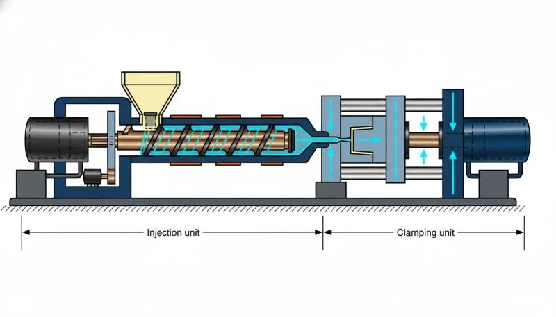
概念上の式は単純で、t_cycle = t_inject + t_pack + t_cool + t_open + t_eject + t_closeです。実際には一部の段階が重なります。スクリュー回復2(次のショットを可塑化する工程)は冷却中に行われるため、t_coolとt_screw_recoveryを足すのではなく、長い方を採用します。
サイクルタイムは固定された特性ではなく、材料、部品形状、金型設計、成形機の設定によって変化します。薄肉のPPキャップなら5~8秒で成形できる一方、厚肉のポリカーボネート製ハウジングでは60秒以上かかる場合があります。エンジニアがよく言う「最適サイクルタイム」とは、すべての品質仕様を満たす部品を安定して繰り返し生産できる最短のサイクルを指します。速めすぎると、ショートショット、ヒケ、寸法のばらつきが発生します。遅すぎると、成形機の稼働時間に無駄なコストを費やすことになります。
サイクルタイムを段階的に計算する方法
サイクルタイムの計算式は、射出、保圧、冷却、金型動作の各時間の合計です。一部の工程は重複します。たとえば、スクリューの可塑化は冷却中に行われるため、両方を加算せず、長い方の時間を採用します。
射出時間 (t_inject)
これは、溶融樹脂がキャビティを充填するまでの時間です。大半の成形品では0.5~5秒です。次式で見積もれます:t_inject = 製品重量(g)÷ 射出速度(g/s)。例えば、100 g/sで射出する成形機で50 gの製品を成形する場合、充填時間は約0.5秒です。ただし、実際の射出プロファイルでは多段速度(低速―高速―低速)を使用するため、実時間は理論上の最短時間よりわずかに長くなります。
保圧時間(t_pack)
キャビティ充填後は、材料収縮を補うために圧力を維持します。この時間は肉厚とゲート固化時間に応じて通常1–10秒です。薄肉部品はすぐに固化しますが、厚肉部品ではより長い保圧が必要です。ゲートが固化してキャビティが封止されると、充填・保圧工程は終了します。
冷却時間(t_cool)
サイクルの大半を占めるのがこの工程です。半結晶性材料では、冷却時間3はおおむね肉厚の二乗に比例します。t_cool ≈ C ×(肉厚)²で、Cは材料の熱拡散率と、溶融樹脂と金型との温度差によって決まります。ABSで肉厚3mmなら15~25秒、5mmなら40~60秒に増えます。
型開閉とエジェクション
金型の開閉には通常、金型サイズと成形機の型締力に応じて2–10秒かかります。80–200Tの成形機に搭載した小型金型では2–4秒、500–1000Tの成形機に搭載した大型金型では6–12秒です。突き出しにはさらに0.5–3秒かかり、自動取出機は手作業による取り出しより高速です。
全体のまとめ
中型ABS筐体(肉厚3mm、80g、型締力200Tの成形機で4個取り金型)の計算例は次のとおりです。t_inject ≈ 1.5s、t_pack ≈ 3s、t_cool ≈ 20s、t_open + t_eject + t_close ≈ 5s。合計サイクルタイムは約29.5秒です。実際の生産では、薄肉包装品の5秒から厚肉の技術部品の90秒超まで、幅広いサイクルを経験しています。
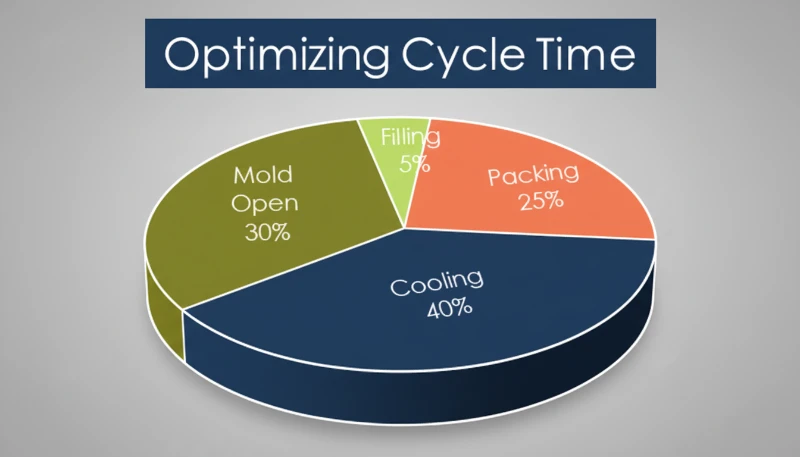
射出成形サイクルの4つの工程とは?
4つの工程は、射出(充填)、保圧(保持)、冷却、突き出し/リセットです。それぞれが部品品質とサイクル効率において異なる役割を担います。
フェーズ1 — 射出(充填)
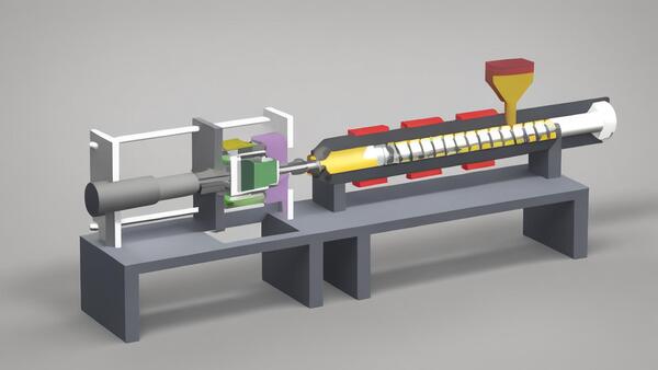
スクリューが前進し、溶融樹脂をランナーとゲートからキャビティ内へ押し込みます。速度が重要です。遅すぎると充填前に溶融樹脂が固まり、速すぎるとジェッティングやバリが発生します。射出時間は通常、最も短い工程ですが、成形品品質の基礎を決定します。
フェーズ2 — 保圧(保持)
キャビティが体積的に充填されると、成形機は保圧に切り替わります。この追加圧力で材料をさらに充填し、成形品が冷却する際の熱収縮を補います。パッキングはゲートが固化してキャビティが密閉されるまで続きます。パッキング時間の設定不良は、ヒケやボイドの一般的な原因です。
フェーズ3 — 冷却
金型を管理された温度(通常は材料に応じて20–80°C)に保ち、変形せずに突き出せるだけの剛性が成形品に得られるまで熱を奪います。この工程が最も長く、総サイクルタイムの60–70%を占めることも少なくありません。その間にスクリューは後退して次のショット分の樹脂を可塑化するため、冷却とスクリュー回復は並行して進みます。
フェーズ4 — 取り出しとリセット
金型が開き、部品が機械またはロボットで取り出された後、次のショットに向けて金型が閉じます。部品が張り付く場合や手作業による検査が必要な場合、離型工程がボトルネックになることがあります。適切に設計されたエジェクタ機構と抜き勾配により、この工程を安定させることができます。
当社の上海工場では、90Tから1850Tまで47台の射出成形機を稼働させています。400種類を超える材料で20年以上にわたる生産経験を蓄積し、サイクルタイムを、8秒で高速成形するPP包装部品から60秒超を要する厚肉PC部品まで最適化してきました。すべての成形機でショットごとのサイクルデータを記録し、継続的な改善に活用しています。
冷却時間がサイクルの大半を占めるのはなぜですか。
冷却はサイクル全体の60–70%を占める主要工程です。厚肉のポリマー壁から熱を除去するには、他のどの工程よりも長い時間を要するためです。
溶融ポリマーは200~300°Cでキャビティに入り、安全に離型できるようになるまで40~80°Cに冷却する必要があります。熱伝達速度は複数の要因に左右されます。
肉厚 — 最重要項目
冷却時間は、最厚部の厚さの二乗にほぼ比例します。厚さ4mmの部品には、厚さ3mmの部品の約1.8倍の冷却時間が必要です。このため、DFMレビューでは常に、均一な肉厚を可能な限り薄くすることが求められます。
材料の熱伝導率
PCやABSなどの非晶性材料は、PAやPOMなどの半結晶性材料とは冷却挙動が異なります。結晶性材料は固化時に潜熱を放出するため、冷却時間が長くなります。材料選定は部品性能だけの問題ではなく、生産採算に直接影響します。
金型温度と冷却チャネル設計
金型温度を低くすると熱をより速く引き抜けますが、冷たすぎると残留応力、反り、または表面仕上げ不良を引き起こします。適切に配置されたバッフル回路、ヒートパイプ、またはコンフォーマル冷却チャネルは、基本的な穴あけチャネルと比較して冷却時間を20〜40%短縮できます。ここが金型工学が費用対効果を発揮する点です。
実用的な意味:サイクルタイムを短縮したいなら、まず冷却を改善せよ。均一な肉厚(変動を25%以下に保つ)、最適化された冷却チャンネルレイアウト、適切な水流量が最大の効果をもたらします。
サイクルタイムに最も大きく影響する要因は?
最も大きな要因は、肉厚、材料の熱特性、金型冷却設計、および機械能力です — おおよそその順序です。
部品形状が最大の要因です。肉厚が厚いほど、冷却時間は指数関数的に長くなります。深いリブ、ボス、または変化する肉厚部分を持つ複雑な部品形状は、ホットスポットを生み出し、最も遅く冷却する領域のために全体のサイクルを延長することを強います。
材料選択は重要です。なぜなら、異なるポリマーは異なる熱特性を持つからです。PPとPEは比較的速く冷却されます。PC、PPSU、および強化ナイロンはより多くの時間を必要とします。サイクル時間が重要で性能が許容される場合、PCからABSに切り替えることで冷却時間を30〜40%削減できます。
金型設計が成否を分けます。重要な要素は、冷却チャンネルの配置と流量、ゲートの種類と位置、エジェクションシステムの信頼性、金型材料の選択です。ベリリウム銅インサートは鋼鉄よりも3~5倍速く熱を伝導し、ホットスポット領域に最適です。機械設定による改善は漸進的です。より高い射出速度、最適化された保圧プロファイル、より速い金型開閉速度はすべて役立ちますが、これらは設計や金型工学に比べれば微調整です。
"冷却時間は通常、射出成形の総サイクルタイムの60~70%を占める。"True
その通りです。当社工場での数千回の生産を通じて、冷却は一貫してサイクルを支配しています。高速サイクルの包装金型であっても、冷却は依然として最も長い単一フェーズです。
"射出速度を上げれば、必ず総サイクルタイムが短縮される。"False
誤りです。最適点を超えると、射出速度を上げるとバリ、ジェッティング、エアトラップが発生し、それを修正するために保圧時間と冷却時間の延長が必要になります。射出速度を上げすぎると、実質的なサイクルタイムが増加する可能性があります。
品質を損なわずにサイクルタイムを最適化するには?
まず冷却の最適化に集中し、次に肉厚の削減、そして機械の調整へと、影響度の高い順に進めてください。以下に、当社が生産で使用している最も効果的な戦略を紹介します。
冷却チャネルの再設計
これは最も投資対効果の高い変更です。金型が基本的な直穴チャネルを使用している場合、バッフル、バブラー、またはスパイラルチャネルに切り替えることで、冷却時間を15〜30%削減できます。大量生産用金型では、コンフォーマル冷却(金属3Dプリントにより実現可能)により、40%以上の削減が可能です。
肉厚の最小化と均一化
最大肉厚を0.5mm削減するごとに、冷却時間を10~20%短縮できます。部品全体の肉厚変動を25%以下に抑えてください。設計チームと早期に協力しましょう。DFM(製造性設計)の変更は、金型が切削される前なら安価ですが、後では高価になります。
ゲート位置とタイプの最適化
ゲート位置を適切にすることで充填の均一性が確保され、保圧時間の延長が必要なくなります。バルブゲート付きホットランナーシステムは、冷却段階とは独立してシールするため、より速いサイクリングが可能です。
エジェクションの自動化
ロボットピッカーや自動落下システムにより、手動での部品取り出しに伴うばらつきが解消されます。これは特に15秒以下のサイクルにおいて、人間の反応時間がボトルネックとなる場合に大きな影響を与えます。
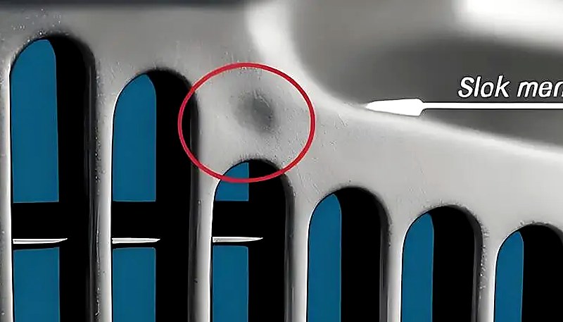
ただし、サイクルタイムの最適化は必ず品質データで検証しなければなりません。短縮後にヒケ、寸法のばらつき、反りが見られる場合は、短縮しすぎです。新しいサイクルを確定する前に、必ず工程能力調査(Cpk)を実施してください。最適化生産に適した製造パートナーの選び方については、射出成形調達ガイドをご覧ください。
"24時間365日稼働する4個取り金型では、成形サイクルを1秒短縮するだけで、年間10万個以上を増産できる。"True
正解です。30秒のサイクルを29秒に短縮すると、4キャビティ金型を連続運転した場合、年間約145,000個の出力増加になります。わずかな最適化でも、大量生産では非常に大きな効果を生みます。
「金型温度を高くすれば、常に部品品質が向上し、サイクルタイムが延びてもその価値がある。」False
誤りです。金型温度を高くすると残留応力が低減し、表面仕上げが改善されることがありますが、冷却時間が延び、過大な収縮を招くおそれもあります。最適な金型温度とは、品質要件とサイクル効率の均衡点であり、単純に「高温ほど良い」というものではありません。
一般的な材料の標準的なサイクルタイムは?
サイクルタイムは大きく異なりますが、以下は肉厚2~3mmの中程度の複雑さの部品における実際の生産データに基づく典型的な範囲です。これらの範囲は、適切な冷却を備えた標準的な金型を前提としています。
| 素材 | 典型的なサイクル(秒) | キーノート |
|---|---|---|
| PP(ポリプロピレン) | 8–25 | 急速冷却、低粘度 — 包装に最適 |
| PE(ポリエチレン) | 8–20 | PPと同様に、良好な流動特性 |
| ABS | 15–40 | 適度な冷却、多用途エンジニアリングプラスチック |
| PS(ポリスチレン) | 10–25 | 急速凍結ですが脆い — 慎重な取り出しが必要 |
| PC(ポリカーボネート) | 25–60 | 高い溶融温度、遅い冷却 |
| PA6(ナイロン6) | 15–45 | 結晶性、十分な冷却が必要 |
| PA66(ナイロン66) | 18–50 | PA6よりも結晶性が高く、冷却時間が長い |
| POM(アセタール) | 15–35 | 良好な熱特性、結晶化が速い |
| TPU | 20–45 | 柔軟性のある材料、エジェクションは遅くする必要あり |
| PBT | 15–35 | 高速結晶化、電気部品に適しています |
最適化したコンフォーマル冷却チャネルを使用すると、多くの場合、これらの範囲より20~30%速く運転できます。要点は、材料選定は成形品性能だけの問題ではなく、サイクルタイムを通じて生産採算に直接影響するということです。
生産時のサイクルタイムをどのように測定・監視するか?
サイクルタイムは成形機内蔵のタイマーで測定し、SPCソフトウェアで追跡して工程ドリフトを早期に検出します。
マシンレベルモニタリング
最新の成形機はすべて、リアルタイムのサイクルタイムを表示します。ほとんどの機種では、サイクルごとのデータを記録し、設定した上限を超えた場合に作業者へ警告できます。これが最初の防御線です。目標を30秒に設定しているのに成形機が32秒を示しているなら、何らかの対応が必要です。
SPCトレンド分析とドリフト検出
数百または数千ショットにわたるサイクルタイムを追跡します。徐々に上昇する傾向は、冷却チャネルの汚れ、エジェクターピンの摩耗、材料粘度の変化など、進行中の問題を示すことが多いです。早期に発見することで、品質問題や計画外のダウンタイムを防ぎます。
サイクルタイム変動の一般的な原因
一般的な要因には、冷却水路のスケール堆積(熱伝達低下)、摩耗したホットランナーノズル(充填遅延・保圧延長)、材料のロット間差異、古い機械の油圧システム劣化、季節による環境温度変化などが挙げられます。
当社の推奨:最適化されたサイクルタイムより5%高いサイクルタイムの上方管理限界(UCL)を設定してください。UCLを超えるショットは調査をトリガーする必要があります。この単純なルールにより、不良品が発生する前に進行中の問題の80%を捕捉できます。本格的な運用では、MES(製造実行システム)がサイクルタイムデータと品質検査結果を統合し、サイクルの変動と部品品質をリアルタイムで相関付けることができます。
よくある質問
射出成形サイクルタイムの公式は何ですか?
基本式は、t_cycle = t_inject + t_pack + t_cool + t_open + t_eject + t_closeです。ただし、一部の工程は重複します――特に冷却とスクリュー回復です。両方を加算するのではなく、長い方の時間を採用します。簡易見積もりでは、冷却時間は通常全体の60–70%を占めるため、冷却時間を計測し1.4–1.6を乗算することで妥当な概算値が得られます。実際のサイクル時間は製品形状、材料、金型設計に依存するため、常に実機データで検証してください。
典型的な射出成形サイクルは何秒ですか?
射出成形サイクルは通常10〜60秒の範囲に収まります。ボトルキャップのような薄肉包装部品は、最適化された高速機では5〜8秒でサイクルできます。2〜3mm肉厚の標準的な技術部品は、従来型プレスでは通常15〜30秒で成形されます。厚肉部品やポリカーボネートのような高性能材料は、冷却時間の延長により45〜90秒まで長引くことがあります。具体的なサイクル時間は、肉厚、材料の熱的特性、金型冷却能力、部品の複雑さに大きく依存します。60秒を超えて常時稼働している場合は、冷却の最適化を検討してください。
射出成形における最も長い工程は何ですか?
冷却はほとんどの生産シナリオでほぼ常に最も長いフェーズであり、総サイクルタイムの60〜70%を消費します。これは、溶融ポリマーから十分な熱を抽出し、変形なく排出できるほど部品を剛性化する必要があるためです。熱力学は避けられません:冷却時間はおおよそ肉厚の2乗に比例して増加し、部品の厚さがわずかに増加しても総サイクルが劇的に延長されることを意味します。薄肉包装部品では、射出時間が重要になる場合もありますが、ほとんどの生産において冷却時間が支配的です。
壁の厚さはサイクルタイムにどのように影響しますか?
肉厚はサイクルタイムの最大の要因です。なぜなら、冷却時間はおおよそ肉厚の2乗に比例して増加するからです。肉厚が2倍になると、必要な冷却時間は約4倍になります。例えば、肉厚2mmの部品は8秒の冷却が必要かもしれませんが、同じ形状で4mmの場合、25〜30秒が必要です。この指数関数的関係のため、製造性を考慮した設計レビューでは常に最小で均一な肉厚が求められます。他の部分よりも著しく厚い部分は、全体のサイクルのボトルネックとなり、すべてのキャビティで冷却時間を延長することを強います。
金型を変更せずにサイクルタイムを短縮できますか?
はい、金型変更なしでサイクルタイムを短縮できますが、金型レベルの改造に比べると効果は限定的です。機械側の最適化には、射出速度の向上、保圧プロファイルの調整、最適な冷却水流量・温度の確保、高速サイクル対応材料グレードへの切替えなどがあります。これらの調整では通常、サイクルタイムの5〜15%改善が得られます。20〜40%以上の大幅な改善には、一般に冷却水路の改良、高温箇所へのベリリウム銅インサートの挿入、効率的な充填のためのゲート再設計などの金型改造が必要です。
射出成形におけるサイクルタイムとリードタイムの違いは何ですか?
サイクルタイムは生産速度を測定するもので、ショットからショットまでの1回の機械サイクルにかかる時間です。リードタイムは注文から納品までの総時間であり、金型製作、材料調達、生産スケジューリング、品質検査、出荷を含みます。サイクルタイムが20秒の部品でも、新規金型の場合は4~6週間のリードタイムがかかる可能性があり、繰り返し生産の場合は3~5日かかります。両方の指標を理解することはプロジェクト計画に不可欠です。金型が準備できていなければ、サイクルタイムが速くても意味がありません。
射出成形における冷却時間はどのように計算しますか?
簡略化された冷却時間の推定には、t_cool = (肉厚の2乗 × 熱係数) ÷ 熱拡散率 の式を使用します。ここで熱係数は、溶融温度と金型温度の温度差に依存します。実際には、ほとんどのエンジニアは経験的な生産データやMoldflowなどの金型シミュレーションソフトウェアに依存しています。なぜなら、実際の部品形状は正確な手計算には複雑すぎるからです。実用的な経験則として、ABSのような非晶性材料で肉厚3mmの場合、15〜25秒を予想してください。同じ肉厚の半結晶性ナイロンの場合は、冷却時間を20〜30%追加してください。
なぜサイクルタイムはショットごとに変動するのですか?
±0.5〜1秒程度のわずかなサイクルタイムの変動は完全に正常であり、材料供給の一貫性のわずかな違い、スクリュー位置の再現性、油圧システムの応答のわずかな違いに起因します。2秒を超える大きな変動は通常、実際の問題を示しています:材料乾燥の不均一、冷却チャネルの詰まりやスケール、ショットサイズ変動を引き起こす摩耗したチェックリング、または故障した温度センサーなどです。数百ショットにわたって徐々に上昇する傾向を観察した場合は、まず冷却水の流量を確認してください。チャネル内部のミネラルスケールの蓄積が、サイクルタイムのゆっくりとした変動の最も一般的な原因です。
射出成形サイクルタイムを最適化する準備はできていますか?
ZetarMoldの技術チームは、400種類を超える材料について生産サイクルを最適化してきた20年以上の経験があります。対応能力の詳細については、射出成形完全ガイドをご覧ください。金型設計レビューから生産条件の調整まで、品質を損なわず最速のサイクルを実現できるよう支援します。次回のプロジェクトについて無料見積もりをご依頼ください。