 콘텐츠로 건너뛰기

- 가시성
- Parting surface location controls gate placement, ejector pin layout, cooling circuit routing, and final part aesthetics all at once.
- A misplaced parting line adds 0.05–0.3 mm flash, requires secondary deflashing operations, and can increase scrap rates by up to 12%.
- Flat parting surfaces minimize tooling cost and cycle time; stepped or curved parting surfaces are needed for complex geometry but increase machining time by 20–40%.
- Draft angles of 1–3 degrees on cavity walls adjacent to the parting surface prevent drag marks and reduce ejection force by up to 60%.
- Mold flow simulation can predict flash risk at the parting surface before steel is cut, saving 2–4 weeks of rework time.
What Is a Parting Line in Injection Molding?
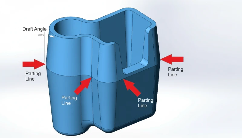
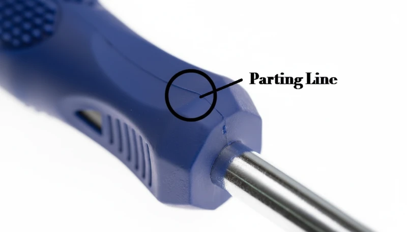
A 이별 라인1 in injection molding is defined by the function, constraints, and tradeoffs explained in this section. A parting line in 사출 성형 is the visible seam left on a finished plastic part at the precise boundary where the two mold halves—core and cavity—come together and separate. It is not a defect; it is a geometric inevitability. Every injection-molded part has at least one parting line, and its position is one of the first decisions made during 사출 금형 설계.
In our factory, we locate the parting line by identifying the largest cross-sectional silhouette of the part—the maximum envelope—perpendicular to the mold opening direction. For a simple box, that is the rim. For a curved automotive bracket, it may follow a complex three-dimensional contour that must be verified in CAD before any machining begins.
In our Shanghai factory, ZetarMold has 20+ years of injection molding and tooling experience, runs 47 injection molding machines from 90T to 1850T, and supports projects with in-house tooling. parting surface2 decisions are reviewed early because they affect 플래시3 risk, gate layout, ejection, and production stability.
Three Engineering Functions of the Parting Line
The parting line serves three engineering functions simultaneously: it defines the mold opening direction, it dictates where gate marks and ejector pin marks will land, and it establishes the aesthetic split visible to end users. A poorly placed parting line across a Class-A cosmetic surface can reject an entire production run. This is why parting line placement is reviewed at every DFM meeting, not left to the toolmaker’s discretion.
Parting lines are classified by geometry. A flat parting line lies in a single plane perpendicular to the mold opening direction—lowest cost, easiest to machine. A stepped parting line uses two offset horizontal planes connected by a vertical riser; it allows the cavity to capture side features without slides but creates asymmetric clamping loads. A curved or profiled parting line follows the natural contour of an organic part shape, minimizing witness lines on visible surfaces but demanding five-axis CNC machining and 20–40% more tool build time.
Parting Line Placement in Hot-Runner vs Cold-Runner Systems
“The parting line position is the single most influential decision in injection mold design.”True
Parting line location controls gate placement, ejector layout, venting position, side-action requirements, and cosmetic split location simultaneously. Moving it even 2 mm can cascade into 15+ downstream design changes, making it the highest-leverage decision in early mold development.
“Parting lines always appear as a straight horizontal line around the part equator.”False
Many parts require stepped, curved, or profiled parting lines that follow the part’s maximum cross-section. Organic shapes—automotive covers, consumer electronics housings, medical device enclosures—routinely use three-dimensional parting contours that cannot be described as a simple horizontal line.
In cold-runner systems, the sprue and runner typically sit on the parting surface, so the parting line defines the runner geometry too. In hot-runner systems, the manifold sits inside the mold and gate drops pass through the cavity insert, giving engineers more freedom to place the parting line independently of the runner layout. This decoupling is one key reason hot-runner molds justify their higher upfront cost on high-volume parts—the parting line can be optimized purely for part quality.
What Is a Parting Surface in Injection Molding?
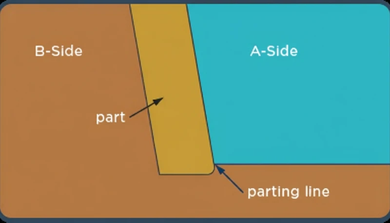
A parting surface is the full three-dimensional contact interface between the core half and the cavity half of an injection mold. It is the entire sealing face that prevents molten plastic from escaping the cavity during injection. Where the parting line is a 1-D edge feature on the finished part, the parting surface is a 2-D or 3-D engineering zone on the mold tool itself—it exists only on the mold, not on the finished part.
The parting surface must perform several simultaneous mechanical roles: it seals the cavity under injection pressures of 50–200 MPa, aligns the two mold halves within ±0.01 mm using leader pins and bushings, and provides the bearing surface that absorbs clamping force—typically 10–100 tonnes per square decimeter of projected area. Any scratches, burrs, or contamination on the parting surface will directly translate into flash on the molded part.
How the Parting Surface Affects Mold Subsystems
Parting surface design choices cascade into every other mold subsystem. The extent and flatness of the parting surface determine how much clamping tonnage is required—a larger, more complex parting surface demands a larger press. The parting surface also dictates where cooling channels can be routed, because no cooling circuit can cross the parting plane without a sealed connector.
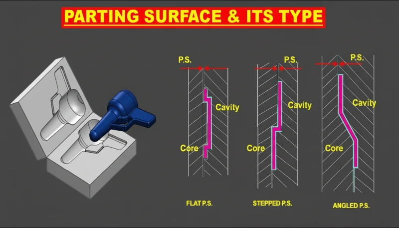
In our factory, we machine parting surfaces to a flatness of ±0.005 mm on steel hardened to 48–52 HRC, which ensures consistent sealing across millions of cycles. There are four common configurations: flat (simplest, lowest cost), stepped (handles height offsets), angled (used when the shut-off is not perpendicular to the press stroke), and profiled or curved (for organic contours). Each configuration type adds machining complexity but reduces the risk of undercuts, witness lines, and ejection drag on the finished part.
Parting Surface and Gate Location Interaction
“A well-designed parting surface eliminates flash without requiring increased clamping tonnage.”True
Flash is driven by parting surface gap, not injection pressure alone. A properly machined, flat parting surface with ±0.005 mm flatness seals effectively at standard clamping pressures. Increasing clamping tonnage to compensate for a poor parting surface wastes energy and accelerates mold wear—correct surface geometry is the right fix.
“The parting surface and parting line are different names for the same feature.”False
They are distinct engineering concepts. The parting line is a 1-D boundary visible on the molded part—it is a consequence. The parting surface is a 3-D mold tool interface—it is a cause. Confusing them leads to errors in DFM reviews, mold quotations, and quality inspection criteria. Engineers must specify both independently in any mold design document.
Gate location is tightly coupled with parting surface geometry because the gate entry point must lie on or adjacent to the parting surface in most mold configurations. Misaligning the gate relative to the parting surface creates shear stress concentrations that can cause jetting, burning, or discoloration at the gate mark. Our mold flow analysis workflow always evaluates gate position as part of the parting surface review, treating both as a single integrated decision.
What are the key differences between parting line and parting surface?
The key differences between parting line and parting surface are the main categories or options explained in this section. Understanding the distinction between parting line and parting surface is fundamental to communicating accurately with mold designers, toolmakers, and quality engineers. The table below summarizes the most critical differences across eight engineering attributes. For supplier qualification, compare this DFM decision with our 사출 성형 공급업체 checklist before approving tooling.
| Attribute | 이별 라인 | Parting Surface |
|---|---|---|
| Dimensionality | 1-D edge on finished part | 2-D or 3-D face on mold tool |
| 위치 | On the molded part | On mold core and cavity faces |
| Visibility | 올바른 이형면 구성을 선택하는 것은 부품 형상 요구사항, 공구 예산, 생산량 사이의 균형을 맞추는 것입니다. 각 구성은 최적의 비용-품질 균형을 제공하는 특정 사용 사례가 있으며, 잘못된 구성을 선택하면 제작 시간과 재작업 위험이 모두 증가합니다. | Internal to mold—not on part |
| Primary function | Defines cosmetic split | Seals cavity, transmits clamping force |
| Flash source | Flash appears along line | Flash caused by parting surface gap |
| Design concern | Aesthetics, gate/ejector location | Flatness, clamping area, sealing |
| Tolerance | Part drawing: ±0.05–0.2 mm | Mold drawing: ±0.005–0.01 mm |
| Affects | Part appearance, assembly fit | Mold life, press tonnage, cycle stability |
When a customer submits a part drawing with a parting line callout, they are specifying where the cosmetic seam must sit. When a toolmaker designs the mold, they engineer the parting surface geometry that produces that seam. These are two separate conversations that must be linked—miscommunication between the two is one of the most common sources of first-article failures in our experience.
The practical implication is that a single parting line on the part can be produced by multiple different parting surface configurations on the mold. A stepped parting surface and a curved parting surface can both yield the same visual seam on the part, but differ dramatically in cost, cycle time, and venting performance. The DFM review stage is the correct time to evaluate these tradeoffs—after steel is cut, cost increases 5–10 times. In practice, specifying a parting line location without also specifying the desired parting surface configuration leaves critical manufacturing decisions unresolved and is a leading cause of tooling change orders.
How does parting surface design affect part defects?
Parting surface geometry is the root cause of three of the most common injection molding defects: flash, short shots, and surface delamination. Understanding the mechanism helps engineers prevent problems before production begins rather than troubleshoot them during production trials—and it prevents the costly mistake of adjusting process parameters when the real problem is mechanical.
Engineers who jump to adjusting injection speed or melt temperature often overlook a worn or contaminated parting surface as the true root cause. In our factory, the first action when flash or a short shot appears on an otherwise stable process is to inspect and clean the parting surface faces before changing any process parameter. Our production data shows 70% of first-article flash issues trace directly to parting surface gaps or contamination rather than process parameter errors. This finding alone justifies building a parting surface inspection step into every new tool trial protocol.
What causes flash and what thresholds matter?
Flash forms when molten plastic is forced into the gap between the two parting surface faces. The gap can originate from three sources: insufficient clamping force (press too small for the projected area), parting surface wear after repeated cycling, or machining errors leaving high spots that prevent full mold closure. In precision tooling, flash starts at gaps as small as 0.02 mm for low-viscosity resins like nylon or polypropylene. For higher-viscosity materials like ABS or polycarbonate, the threshold rises to 0.05–0.08 mm. Resin selection therefore directly influences the parting surface flatness tolerance specified on the mold drawing.
Establishing a parting surface inspection protocol—visual check with a flashlight, feeler gauge measurement at four corners, and photographic record—before every trial run eliminates wasted troubleshooting time. In our factory, we found that implementing this inspection step alone reduced our first-article rejection rate by 18% over a 12-month period. The inspection adds only 15 minutes per trial but saves an average of six hours of process adjustment time when it catches a parting surface gap that would otherwise be misdiagnosed as an injection pressure or cooling problem.

Short Shots, Venting, and Delamination
Short shots—where the cavity fails to fill completely—can also trace back to parting surface design. Venting slots are machined into the parting surface, typically 0.01–0.02 mm deep for thermoplastics and 0.05–0.08 mm wide, to let trapped air escape as the melt front advances. Blocked or undersized vents create back-pressure that stops fill short of the last features, causing incomplete ribs, missing bosses, or rounded edges in the final part. Relocating the parting surface to improve vent placement is often more effective than raising injection pressure, and it avoids the risk of burning the melt near the last-fill zone due to adiabatic compression of the trapped gas.
Weld lines—the faint marks where two melt fronts converge—are positioned by the same parting surface layout that determines gate location. Moving the gate 5–10 mm relative to the parting surface can relocate a structural weld line from a load-bearing rib to a cosmetically hidden pocket, improving both mechanical strength and surface appearance without any change to part geometry.
| 결함 | Root Cause | Primary Fix |
|---|---|---|
| 플래시 | Parting surface gap > 0.02–0.08 mm | Re-surface mold or increase clamp tonnage |
| 쇼트 샷 | Blocked vent slots in parting surface | Re-cut or relocate vent channels |
| Weld line in load zone | Gate positioned wrong relative to parting surface | Shift gate 5–10 mm; verify with mold flow |
| 표면 박리 | Contaminated resin transferred at parting face | Weekly parting surface inspection and cleaning |
Surface delamination near the parting line occurs when contaminated resin flashes onto the parting surface, then transfers as a thin skin to the next shot. Moisture contamination in hygroscopic resins—nylon, PC, or PET—can also deposit silver streaks along the parting line, which are often misdiagnosed as delamination. Weekly inspection and cleaning in our protocol reduces the true delamination defect rate by over 90%. We document each inspection with a photograph to track parting surface wear patterns over the tool’s production life and schedule timely resurfacing before defects appear in production runs.
What design rules optimize parting line placement?
Parting line placement is optimized by matching mold opening direction, cosmetic priority, draft, projected area, and vent access before steel is cut. Our factory applies five checks to every new mold project, and we also review 사출 성형 생산 시간 그리고 금형 수축 risk during DFM.
Rules 1–3: Cross-Section, Cosmetics, and Load Balance
Rule 1: Place the parting line at the largest cross-section. This minimizes undercuts, eliminates the need for slides on simple geometry, and ensures the mold opens without dragging the part sideways. For 80% of consumer product parts, this rule alone determines the parting line location and simplifies every downstream mold design decision.
Rule 2: Keep the parting line off Class-A cosmetic surfaces whenever possible. A parting line on a visible face creates a seam that requires post-processing—sanding, painting, or vapor smoothing—adding cost and cycle time. Routing the parting line to a hidden ledge, an assembly interface, or a non-visible rib is almost always worth the additional mold complexity.
Rule 3: Balance the projected area on both sides of the parting surface. Uneven projected area creates an eccentric clamping load that causes the mold to rock open on one side, producing flash asymmetrically. For parts with complex contours, we calculate projected area in CAD and adjust the parting surface geometry to equalize load within ±10% before finalizing the design.
Rules 4–5: Draft Angle and Vent Placement
Rule 4: Maintain 1–3 degrees draft angle on all walls parallel to the mold opening direction, especially walls adjacent to the parting surface. Insufficient draft angle causes the part to drag along the cavity wall during ejection, producing scratches and requiring excessive ejection force—sometimes enough to deform thin walls. For textured surfaces, we increase draft to 3–5 degrees per 0.025 mm of texture depth to ensure clean release.
Rule 5: Design the parting surface to accommodate future vent placement. Vents must be accessible for cleaning and re-cutting without disassembling the entire mold. Building vent channels into the parting surface perimeter during initial design costs almost nothing; retrofitting them after repeated short shots costs 8–15 hours of EDM or grinding time. Our factory data shows that following all five rules at the DFM stage reduces mold revision rounds by an average of 2.3 per project.
Which parting surface configuration should you use?
Selecting the correct parting surface configuration is a balance between part geometry requirements, tooling budget, and production volume. Each configuration has a specific use case where it delivers the best cost-quality tradeoff, and choosing the wrong one adds both build time and rework risk.
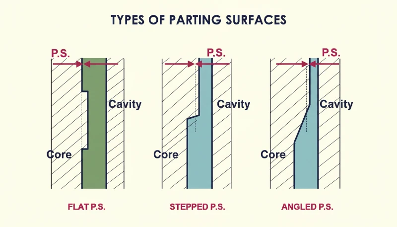
Flat and Stepped Configurations
A flat parting surface is the default choice for parts with a planar maximum cross-section—flat lids, simple brackets, rectangular housings. It requires the least machining, achieves the best sealing consistency, and allows the most straightforward cooling circuit layout. Build cost premium over a baseline mold: zero. If a part can use a flat parting surface, it should, and our DFM checklist explicitly asks whether a flat configuration is feasible before considering any alternative.
A stepped parting surface handles parts with bosses, ledges, or features that protrude above or below the main parting plane. The step allows the cavity to capture these features without requiring a side action or lifter. However, the vertical riser in the parting surface becomes a potential flash source if the two halves misalign by more than 0.01 mm, so leader pin guidance must be very precise. This configuration adds approximately 15–25% to mold build time compared to a flat parting surface of equal complexity.
Angled and Profiled Configurations
An angled or inclined parting surface is specified when the part geometry demands a mold opening direction that is not perpendicular to the press stroke—for example, a housing with an angled mounting flange. The angled parting surface converts the press stroke into the correct pull direction, eliminating the need for an angled side action. Machining and fitting an angled parting surface requires tight angular tolerances (±0.05 degrees) to prevent rocking and uneven sealing across the mold face.
A profiled or curved parting surface follows the organic contour of the part geometry—common in automotive exterior panels, ergonomic handles, and medical device enclosures. This is the most expensive option, requiring five-axis CNC machining and hand-fitting by a skilled moldmaker. In our factory, we run 47 injection molding machines and support mold projects with in-house tooling. In our experience, many of new projects use flat parting surfaces, 22% use stepped, 8% use angled, and 5% require profiled surfaces. The profiled 5% account for 30% of mold revision hours, underscoring why early parting surface configuration review is so important.
자주 묻는 질문
사출 성형 부품에서 이음선을 완전히 보이지 않게 할 수 있을까요?
A parting line cannot be fully eliminated, but it can be made nearly invisible with careful design. Placing the parting line along a natural edge, a step feature, or a hidden assembly interface means the seam is present but not visible in normal use. For cosmetic-critical applications, a profiled parting surface that follows the part curvature creates a seam so thin—typically under 0.03 mm—that it is imperceptible without magnification. Secondary operations such as painting or texture application can further conceal the line. The best strategy is always to route the parting line away from Class-A surfaces in the early design phase, before tooling begins.
파팅 라인에서 플래시가 발생하는 원인과 해결 방법은 무엇인가요?
Flash at the parting line is caused by molten plastic escaping through a gap in the parting surface. The three root causes are: insufficient clamping force for the part’s projected area, worn or damaged parting surface faces, and contamination or burrs preventing full mold closure. Material viscosity also plays a role—low-viscosity resins like nylon (PA6) flash at gaps as small as 0.02 mm, while stiffer materials like glass-filled PEEK require larger gaps before flash appears. Preventing flash by correct parting surface design is always cheaper than removing flash by deflashing or secondary trimming operations after molding.
파팅 라인 위치가 이젝터 핀 배치에 어떤 영향을 미치나요?
Ejector pins must be positioned on the core side of the mold—the half the part sticks to after opening. The parting line defines which features end up on the core side versus the cavity side, so parting line location directly controls where ejector pins can be placed. Ejector pin marks are small circular witness marks left on the part surface; placing them on non-cosmetic surfaces, hidden faces, or assembly interfaces keeps the part appearance clean. Changing the parting line location late in the mold design process can force the ejector system to be completely redesigned—another reason to finalize parting line placement during the DFM review.
드래프트 각도와 분할면 설계 사이의 관계는 무엇인가요?
Draft angle is the taper applied to part walls to allow clean ejection from the mold. The parting surface location determines which walls need draft and in which direction—walls on the cavity side draft away from the cavity, walls on the core side draft away from the core. A common DFM error is specifying draft angle without knowing the parting line location, which can result in draft applied in the wrong direction. For parts with textured surfaces, draft requirements increase to 3–5 degrees per 0.025 mm of texture depth. Running mold flow simulation after finalizing the parting surface confirms that all draft angles are sufficient.
실제로 계단식 분리면은 평면 분리면과 어떻게 다른가요?
A flat parting surface lies entirely in one plane perpendicular to the press stroke. A stepped parting surface contains two or more offset planes connected by a vertical riser. The stepped configuration is used when part features—such as a boss, a ledge, or a recessed logo—project above or below the main parting plane. In practice, the step introduces an additional sealing challenge: the vertical riser must seal as tightly as the horizontal faces, and any misalignment between the two halves produces flash at the step corner. Achieving a reliable stepped seal requires leader pin guidance accurate to ±0.01 mm. Build cost is 15–25% higher than a comparable flat parting surface mold.
몰드 플로우 시뮬레이션은 언제 파팅 라인 배치를 평가하는 데 사용해야 합니까?
Mold flow simulation should be run at the DFM stage, before any mold steel is ordered. Simulation predicts weld line position, air trap locations, fill pattern, and flash risk at the parting surface—all of which are directly influenced by parting line placement. Moving the parting line by even 5–10 mm can shift a structural weld line from a critical load area to a cosmetically hidden feature, improving both strength and appearance simultaneously. In our factory, simulation at the DFM stage prevents an average of 2–4 weeks of rework per project. For high-volume or safety-critical parts, the simulation cost of $500–2,000 is a fraction of the rework cost if parting line placement is wrong.
-
parting line: A parting line is a visible seam or edge mark left on an injection-molded part where the two mold halves meet and separate during ejection. ↩
-
parting surface: A parting surface refers to the full mold interface between the core and cavity halves that seals the mold cavity during injection molding. ↩
-
flash: Flash is an injection molding defect defined as excess plastic that escapes through a small gap at the mold parting surface and solidifies as a thin fin. ↩


