 Ir al contenido

- En las caras del núcleo y la cavidad del molde
- Parting surface location controls gate placement, ejector pin layout, cooling circuit routing, and final part aesthetics all at once.
- A misplaced parting line adds 0.05–0.3 mm flash, requires secondary deflashing operations, and can increase scrap rates by up to 12%.
- Flat parting surfaces minimize tooling cost and cycle time; stepped or curved parting surfaces are needed for complex geometry but increase machining time by 20–40%.
- Draft angles of 1–3 degrees on cavity walls adjacent to the parting surface prevent drag marks and reduce ejection force by up to 60%.
- Mold flow simulation can predict flash risk at the parting surface before steel is cut, saving 2–4 weeks of rework time.
¿Qué es una Línea de Partición en el Moldeo por Inyección?
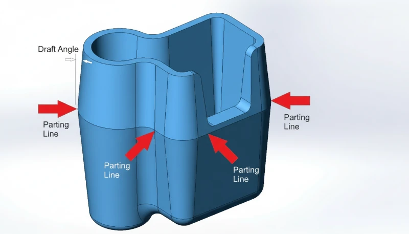
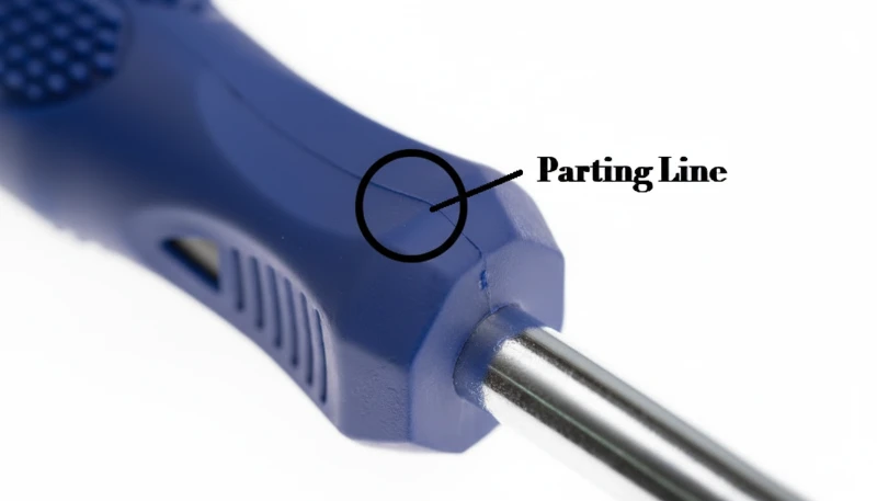
A línea de partición1 en el moldeo por inyección se define por la función, las restricciones y las compensaciones explicadas en esta sección. Una línea de partición en moldeo por inyección es la costura visible que queda en una pieza de plástico terminada en el límite preciso donde las dos mitades del molde—núcleo y cavidad—se unen y separan. No es un defecto; es una inevitabilidad geométrica. Cada pieza moldeada por inyección tiene al menos una línea de partición, y su posición es una de las primeras decisiones tomadas durante diseño de moldes de inyección.
In our factory, we locate the parting line by identifying the largest cross-sectional silhouette of the part—the maximum envelope—perpendicular to the mold opening direction. For a simple box, that is the rim. For a curved automotive bracket, it may follow a complex three-dimensional contour that must be verified in CAD before any machining begins.
En nuestra fábrica de Shanghái, ZetarMold cuenta con más de 20 años de experiencia en moldeo por inyección y fabricación de herramientas, opera 47 máquinas de moldeo por inyección de 90T a 1850T y respalda proyectos con fabricación de herramientas interna. superficie de partición2 las decisiones se revisan temprano porque afectan flash3 riesgo, disposición de la entrada, expulsión y estabilidad de la producción.
Three Engineering Functions of the Parting Line
The parting line serves three engineering functions simultaneously: it defines the mold opening direction, it dictates where gate marks and ejector pin marks will land, and it establishes the aesthetic split visible to end users. A poorly placed parting line across a Class-A cosmetic surface can reject an entire production run. This is why parting line placement is reviewed at every DFM meeting, not left to the toolmaker’s discretion.
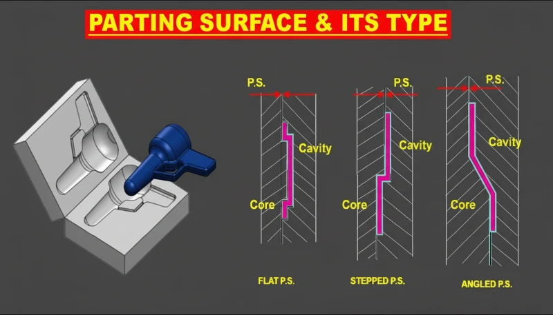
Parting lines are classified by geometry. A flat parting line lies in a single plane perpendicular to the mold opening direction—lowest cost, easiest to machine. A stepped parting line uses two offset horizontal planes connected by a vertical riser; it allows the cavity to capture side features without slides but creates asymmetric clamping loads. A curved or profiled parting line follows the natural contour of an organic part shape, minimizing witness lines on visible surfaces but demanding five-axis CNC machining and 20–40% more tool build time.
Parting Line Placement in Hot-Runner vs Cold-Runner Systems
“The parting line position is the single most influential decision in injection mold design.”Verdadero
Parting line location controls gate placement, ejector layout, venting position, side-action requirements, and cosmetic split location simultaneously. Moving it even 2 mm can cascade into 15+ downstream design changes, making it the highest-leverage decision in early mold development.
“Parting lines always appear as a straight horizontal line around the part equator.”Falso
Many parts require stepped, curved, or profiled parting lines that follow the part’s maximum cross-section. Organic shapes—automotive covers, consumer electronics housings, medical device enclosures—routinely use three-dimensional parting contours that cannot be described as a simple horizontal line.
En los sistemas de canal frío, el bebedero y el canal suelen ubicarse en la superficie de partición, por lo que la línea de partición también define la geometría del canal. En los sistemas de canal caliente, el colector se encuentra dentro del molde y las gotas de compuerta pasan a través del inserto de la cavidad, lo que brinda a los ingenieros mayor libertad para colocar la línea de partición independientemente del diseño del canal. Este desacoplamiento es una razón clave por la que los moldes de canal caliente justifican su mayor costo inicial en piezas de alto volumen: la línea de partición puede optimizarse únicamente para la calidad de la pieza.
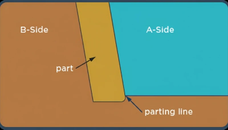
What Is a Parting Surface in Injection Molding?
A parting surface is the full three-dimensional contact interface between the core half and the cavity half of an injection mold. It is the entire sealing face that prevents molten plastic from escaping the cavity during injection. Where the parting line is a 1-D edge feature on the finished part, the parting surface is a 2-D or 3-D engineering zone on the mold tool itself—it exists only on the mold, not on the finished part.
La superficie de partición debe desempeñar varios roles mecánicos simultáneos: sella la cavidad bajo presiones de inyección de 50–200 MPa, alinea las dos mitades del molde dentro de ±0.01 mm usando pasadores guía y bujes, y proporciona la superficie de apoyo que absorbe la fuerza de cierre, típicamente de 10–100 toneladas por decímetro cuadrado de área proyectada. Cualquier arañazo, rebaba o contaminación en la superficie de partición se traducirá directamente en rebabas en la pieza moldeada.
How the Parting Surface Affects Mold Subsystems
Parting surface design choices cascade into every other mold subsystem. The extent and flatness of the parting surface determine how much clamping tonnage is required—a larger, more complex parting surface demands a larger press. The parting surface also dictates where cooling channels can be routed, because no cooling circuit can cross the parting plane without a sealed connector.
In our factory, we machine parting surfaces to a flatness of ±0.005 mm on steel hardened to 48–52 HRC, which ensures consistent sealing across millions of cycles. There are four common configurations: flat (simplest, lowest cost), stepped (handles height offsets), angled (used when the shut-off is not perpendicular to the press stroke), and profiled or curved (for organic contours). Each configuration type adds machining complexity but reduces the risk of undercuts, witness lines, and ejection drag on the finished part.
Parting Surface and Gate Location Interaction
“A well-designed parting surface eliminates flash without requiring increased clamping tonnage.”Verdadero
Flash is driven by parting surface gap, not injection pressure alone. A properly machined, flat parting surface with ±0.005 mm flatness seals effectively at standard clamping pressures. Increasing clamping tonnage to compensate for a poor parting surface wastes energy and accelerates mold wear—correct surface geometry is the right fix.
“The parting surface and parting line are different names for the same feature.”Falso
They are distinct engineering concepts. The parting line is a 1-D boundary visible on the molded part—it is a consequence. The parting surface is a 3-D mold tool interface—it is a cause. Confusing them leads to errors in DFM reviews, mold quotations, and quality inspection criteria. Engineers must specify both independently in any mold design document.
La ubicación de la compuerta está estrechamente vinculada con la geometría de la superficie de partición porque el punto de entrada de la compuerta debe estar sobre o adyacente a la superficie de partición en la mayoría de las configuraciones de molde. Desalinear la compuerta con respecto a la superficie de partición crea concentraciones de esfuerzo cortante que pueden causar chorreo, quemaduras o decoloración en la marca de la compuerta. Nuestro flujo de trabajo de análisis de flujo de molde siempre evalúa la posición de la compuerta como parte de la revisión de la superficie de partición, tratando ambas como una decisión integrada única.
¿Cuáles son las diferencias clave entre la línea de partición y la superficie de partición?
Las diferencias clave entre línea de partición y superficie de partición son las principales categorías u opciones explicadas en esta sección. Comprender la distinción entre línea de partición y superficie de partición es fundamental para comunicarse con precisión con diseñadores de moldes, fabricantes de herramientas e ingenieros de calidad. La siguiente tabla resume las diferencias más críticas en ocho atributos de ingeniería. Para la calificación de proveedores, compare esta decisión de DFM con nuestro proveedor de moldeo por inyección lista de verificación antes de aprobar la herramienta.
| Attribute | Línea de separación | Parting Surface |
|---|---|---|
| Dimensionality | 1-D edge on finished part | 2-D or 3-D face on mold tool |
| Ubicación | On the molded part | On mold core and cavity faces |
| y Colocación de Ventilación | Visible seam to end user | Internal to mold—not on part |
| Primary function | Defines cosmetic split | Seals cavity, transmits clamping force |
| Flash source | Flash appears along line | Flash caused by parting surface gap |
| Design concern | Aesthetics, gate/ejector location | Flatness, clamping area, sealing |
| Tolerance | Part drawing: ±0.05–0.2 mm | Mold drawing: ±0.005–0.01 mm |
| Affects | Part appearance, assembly fit | Mold life, press tonnage, cycle stability |
When a customer submits a part drawing with a parting line callout, they are specifying where the cosmetic seam must sit. When a toolmaker designs the mold, they engineer the parting surface geometry that produces that seam. These are two separate conversations that must be linked—miscommunication between the two is one of the most common sources of first-article failures in our experience.
La implicación práctica es que una sola línea de partición en la pieza puede producirse mediante múltiples configuraciones diferentes de la superficie de partición en el molde. Una superficie de partición escalonada y una superficie de partición curva pueden producir la misma costura visual en la pieza, pero difieren drásticamente en costo, tiempo de ciclo y rendimiento de ventilación. La etapa de revisión DFM es el momento correcto para evaluar estas compensaciones; después de cortar el acero, el costo aumenta de 5 a 10 veces. En la práctica, especificar una ubicación de la línea de partición sin especificar también la configuración deseada de la superficie de partición deja decisiones críticas de fabricación sin resolver y es una de las principales causas de órdenes de cambio de herramental.
¿Cómo afecta el diseño de la superficie de partición a los defectos de la pieza?
La geometría de la superficie de partición es la causa principal de tres de los defectos más comunes en el moldeo por inyección: rebabas, piezas incompletas y delaminación superficial. Comprender el mecanismo ayuda a los ingenieros a prevenir problemas antes de que comience la producción, en lugar de solucionarlos durante las pruebas de producción, y evita el costoso error de ajustar los parámetros del proceso cuando el problema real es mecánico.
Engineers who jump to adjusting injection speed or melt temperature often overlook a worn or contaminated parting surface as the true root cause. In our factory, the first action when flash or a short shot appears on an otherwise stable process is to inspect and clean the parting surface faces before changing any process parameter. Our production data shows 70% of first-article flash issues trace directly to parting surface gaps or contamination rather than process parameter errors. This finding alone justifies building a parting surface inspection step into every new tool trial protocol.
¿Qué causa las rebabas y qué umbrales importan?
Flash forms when molten plastic is forced into the gap between the two parting surface faces. The gap can originate from three sources: insufficient clamping force (press too small for the projected area), parting surface wear after repeated cycling, or machining errors leaving high spots that prevent full mold closure. In precision tooling, flash starts at gaps as small as 0.02 mm for low-viscosity resins like nylon or polypropylene. For higher-viscosity materials like ABS or polycarbonate, the threshold rises to 0.05–0.08 mm. Resin selection therefore directly influences the parting surface flatness tolerance specified on the mold drawing.
Establishing a parting surface inspection protocol—visual check with a flashlight, feeler gauge measurement at four corners, and photographic record—before every trial run eliminates wasted troubleshooting time. In our factory, we found that implementing this inspection step alone reduced our first-article rejection rate by 18% over a 12-month period. The inspection adds only 15 minutes per trial but saves an average of six hours of process adjustment time when it catches a parting surface gap that would otherwise be misdiagnosed as an injection pressure or cooling problem.

Short Shots, Venting, and Delamination
Short shots—where the cavity fails to fill completely—can also trace back to parting surface design. Venting slots are machined into the parting surface, typically 0.01–0.02 mm deep for thermoplastics and 0.05–0.08 mm wide, to let trapped air escape as the melt front advances. Blocked or undersized vents create back-pressure that stops fill short of the last features, causing incomplete ribs, missing bosses, or rounded edges in the final part. Relocating the parting surface to improve vent placement is often more effective than raising injection pressure, and it avoids the risk of burning the melt near the last-fill zone due to adiabatic compression of the trapped gas.
Weld lines—the faint marks where two melt fronts converge—are positioned by the same parting surface layout that determines gate location. Moving the gate 5–10 mm relative to the parting surface can relocate a structural weld line from a load-bearing rib to a cosmetically hidden pocket, improving both mechanical strength and surface appearance without any change to part geometry.
| Defecto | Root Cause | Primary Fix |
|---|---|---|
| Flash | Parting surface gap > 0.02–0.08 mm | Re-surface mold or increase clamp tonnage |
| Tiro corto | Blocked vent slots in parting surface | Re-cut or relocate vent channels |
| Weld line in load zone | Gate positioned wrong relative to parting surface | Shift gate 5–10 mm; verify with mold flow |
| Deslaminación superficial | Contaminated resin transferred at parting face | Weekly parting surface inspection and cleaning |
Surface delamination near the parting line occurs when contaminated resin flashes onto the parting surface, then transfers as a thin skin to the next shot. Moisture contamination in hygroscopic resins—nylon, PC, or PET—can also deposit silver streaks along the parting line, which are often misdiagnosed as delamination. Weekly inspection and cleaning in our protocol reduces the true delamination defect rate by over 90%. We document each inspection with a photograph to track parting surface wear patterns over the tool’s production life and schedule timely resurfacing before defects appear in production runs.
¿Qué reglas de diseño optimizan la ubicación de la línea de partición?
La ubicación de la línea de partición se optimiza haciendo coincidir la dirección de apertura del molde, la prioridad cosmética, el ángulo de desmoldeo, el área proyectada y el acceso de ventilación antes de cortar el acero. Nuestra fábrica aplica cinco verificaciones a cada nuevo proyecto de molde y también revisamos tiempo de producción del moldeo por inyección y contracción del molde riesgo durante el DFM.
Rules 1–3: Cross-Section, Cosmetics, and Load Balance
Rule 1: Place the parting line at the largest cross-section. This minimizes undercuts, eliminates the need for slides on simple geometry, and ensures the mold opens without dragging the part sideways. For 80% of consumer product parts, this rule alone determines the parting line location and simplifies every downstream mold design decision.
Rule 2: Keep the parting line off Class-A cosmetic surfaces whenever possible. A parting line on a visible face creates a seam that requires post-processing—sanding, painting, or vapor smoothing—adding cost and cycle time. Routing the parting line to a hidden ledge, an assembly interface, or a non-visible rib is almost always worth the additional mold complexity.
Rule 3: Balance the projected area on both sides of the parting surface. Uneven projected area creates an eccentric clamping load that causes the mold to rock open on one side, producing flash asymmetrically. For parts with complex contours, we calculate projected area in CAD and adjust the parting surface geometry to equalize load within ±10% before finalizing the design.
Reglas 4–5: Ángulo de desmoldeo y colocación de ventilación
Línea de Partición vs Superficie de Partición: Una Guía para Ingenieros
Rule 5: Design the parting surface to accommodate future vent placement. Vents must be accessible for cleaning and re-cutting without disassembling the entire mold. Building vent channels into the parting surface perimeter during initial design costs almost nothing; retrofitting them after repeated short shots costs 8–15 hours of EDM or grinding time. Our factory data shows that following all five rules at the DFM stage reduces mold revision rounds by an average of 2.3 per project.
¿Qué configuración de superficie de partición debería usar?
Selecting the correct parting surface configuration is a balance between part geometry requirements, tooling budget, and production volume. Each configuration has a specific use case where it delivers the best cost-quality tradeoff, and choosing the wrong one adds both build time and rework risk.
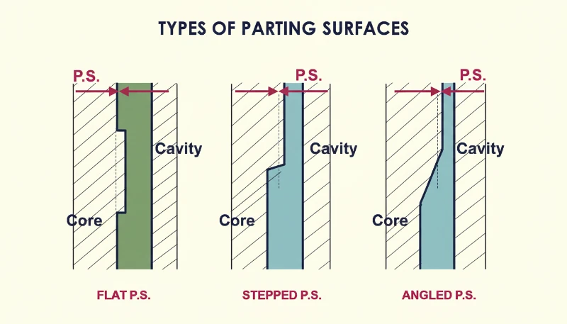
Flat and Stepped Configurations
A flat parting surface is the default choice for parts with a planar maximum cross-section—flat lids, simple brackets, rectangular housings. It requires the least machining, achieves the best sealing consistency, and allows the most straightforward cooling circuit layout. Build cost premium over a baseline mold: zero. If a part can use a flat parting surface, it should, and our DFM checklist explicitly asks whether a flat configuration is feasible before considering any alternative.
A stepped parting surface handles parts with bosses, ledges, or features that protrude above or below the main parting plane. The step allows the cavity to capture these features without requiring a side action or lifter. However, the vertical riser in the parting surface becomes a potential flash source if the two halves misalign by more than 0.01 mm, so leader pin guidance must be very precise. This configuration adds approximately 15–25% to mold build time compared to a flat parting surface of equal complexity.
Angled and Profiled Configurations
An angled or inclined parting surface is specified when the part geometry demands a mold opening direction that is not perpendicular to the press stroke—for example, a housing with an angled mounting flange. The angled parting surface converts the press stroke into the correct pull direction, eliminating the need for an angled side action. Machining and fitting an angled parting surface requires tight angular tolerances (±0.05 degrees) to prevent rocking and uneven sealing across the mold face.
Una superficie de partición perfilada o curva sigue el contorno orgánico de la geometría de la pieza, común en paneles exteriores automotrices, mangos ergonómicos y carcasas de dispositivos médicos. Esta es la opción más costosa, que requiere mecanizado CNC de cinco ejes y ajuste manual por parte de un moldeador calificado. En nuestra fábrica, operamos 47 máquinas de moldeo por inyección y apoyamos proyectos de moldes con herramental interno. Según nuestra experiencia, muchos de los nuevos proyectos utilizan superficies de partición planas, el 22% usa escalonadas, el 8% usa anguladas y el 5% requiere superficies perfiladas. El 5% perfilado representa el 30% de las horas de revisión del molde, lo que subraya por qué la revisión temprana de la configuración de la superficie de partición es tan importante.
Preguntas frecuentes
Can a parting line be completely invisible on an injection-molded part?
A parting line cannot be fully eliminated, but it can be made nearly invisible with careful design. Placing the parting line along a natural edge, a step feature, or a hidden assembly interface means the seam is present but not visible in normal use. For cosmetic-critical applications, a profiled parting surface that follows the part curvature creates a seam so thin—typically under 0.03 mm—that it is imperceptible without magnification. Secondary operations such as painting or texture application can further conceal the line. The best strategy is always to route the parting line away from Class-A surfaces in the early design phase, before tooling begins.
What causes flash at the parting line and how is it fixed?
Flash at the parting line is caused by molten plastic escaping through a gap in the parting surface. The three root causes are: insufficient clamping force for the part’s projected area, worn or damaged parting surface faces, and contamination or burrs preventing full mold closure. Material viscosity also plays a role—low-viscosity resins like nylon (PA6) flash at gaps as small as 0.02 mm, while stiffer materials like glass-filled PEEK require larger gaps before flash appears. Preventing flash by correct parting surface design is always cheaper than removing flash by deflashing or secondary trimming operations after molding.
How does parting line location affect ejector pin placement?
Ejector pins must be positioned on the core side of the mold—the half the part sticks to after opening. The parting line defines which features end up on the core side versus the cavity side, so parting line location directly controls where ejector pins can be placed. Ejector pin marks are small circular witness marks left on the part surface; placing them on non-cosmetic surfaces, hidden faces, or assembly interfaces keeps the part appearance clean. Changing the parting line location late in the mold design process can force the ejector system to be completely redesigned—another reason to finalize parting line placement during the DFM review.
What is the relationship between draft angle and parting surface design?
Draft angle is the taper applied to part walls to allow clean ejection from the mold. The parting surface location determines which walls need draft and in which direction—walls on the cavity side draft away from the cavity, walls on the core side draft away from the core. A common DFM error is specifying draft angle without knowing the parting line location, which can result in draft applied in the wrong direction. For parts with textured surfaces, draft requirements increase to 3–5 degrees per 0.025 mm of texture depth. Running mold flow simulation after finalizing the parting surface confirms that all draft angles are sufficient.
How does a stepped parting surface differ from a flat parting surface in practice?
A flat parting surface lies entirely in one plane perpendicular to the press stroke. A stepped parting surface contains two or more offset planes connected by a vertical riser. The stepped configuration is used when part features—such as a boss, a ledge, or a recessed logo—project above or below the main parting plane. In practice, the step introduces an additional sealing challenge: the vertical riser must seal as tightly as the horizontal faces, and any misalignment between the two halves produces flash at the step corner. Achieving a reliable stepped seal requires leader pin guidance accurate to ±0.01 mm. Build cost is 15–25% higher than a comparable flat parting surface mold.
When should mold flow simulation be used to evaluate parting line placement?
Mold flow simulation should be run at the DFM stage, before any mold steel is ordered. Simulation predicts weld line position, air trap locations, fill pattern, and flash risk at the parting surface—all of which are directly influenced by parting line placement. Moving the parting line by even 5–10 mm can shift a structural weld line from a critical load area to a cosmetically hidden feature, improving both strength and appearance simultaneously. In our factory, simulation at the DFM stage prevents an average of 2–4 weeks of rework per project. For high-volume or safety-critical parts, the simulation cost of $500–2,000 is a fraction of the rework cost if parting line placement is wrong.
-
parting line: Una línea de partición es una costura visible o marca de borde que queda en una pieza moldeada por inyección donde las dos mitades del molde se encuentran y separan durante la expulsión. ↩
-
parting surface: Una superficie de partición se refiere a toda la interfaz del molde entre las mitades del núcleo y la cavidad que sella la cavidad del molde durante el moldeo por inyección. ↩
-
flash: El rebaba es un defecto de moldeo por inyección definido como plástico excedente que escapa a través de un pequeño espacio en la superficie de partición del molde y se solidifica como una aleta delgada. ↩


