이 10가지 요소가 사출 금형 품질을 결정하는 이유는 무엇입니까?
사출 금형 품질은 원재료 특성, 금형강 선택, 냉각 시스템 설계, 게이트 설계, 러너 시스템, 이젝션 시스템, 파팅면 품질, 공정 매개변수 제어, 기계 상태 및 예방 정비라는 열 가지 핵심 요소의 상호작용으로 결정됩니다. 당사 공장에서는 첫 생산 가동 전에 모든 신규 금형에 대해 이 열 가지를 체계적으로 평가합니다. 나머지를 무시한 채 한두 가지만 다루면 여러 변수의 상호작용으로 근본 원인이 가려져 진단하기 어려운 품질 문제가 지속적으로 발생합니다.
10가지 요인의 가중치는 모든 프로젝트에서 동일하지 않습니다. 치수 공차가 엄격한 의료기기 하우징에서는 소재 품질과 냉각 균일성이 가장 중요합니다. 고광택 소비재에서는 파팅면 품질과 게이트 위치가 가장 중요합니다. 대량 범용 부품에서는 기계 상태와 유지보수 일정이 장기적인 품질 일관성을 좌우합니다. 특정 용도에서 어떤 요인이 가장 중요한지 이해하는 것이 품질 관리 계획 수립의 첫 단계입니다.
원재료 품질은 사출 금형 생산량에 어떤 영향을 미칩니까?
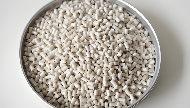
원재료 품질은 사출 성형 품질의 기초 변수입니다—다른 모든 요소는 배럴로 들어가는 재료에 작용합니다. 불량한 원재료 품질은 일관되지 않은 점도, 오염에 의한 변색, 수분 관련 결함(스플레이, 기포) 및 예측 불가능한 수축으로 나타납니다. 우리 시설에서 첫 샷 품질 불량의 25% 이상을 재료 로트 변동 또는 사전 건조 실패로 추적했습니다.
| 재료 문제 | 발생 결함 | 예방 방법 |
|---|---|---|
| 건조 부족(흡습성 수지) | 은줄, 기포, 표면 마감 저하 | 사양에 맞게 건조: ABS 80°C/4h, PC 120°C/4h, 나일론 80°C/6h |
| 로트 간 MFI 편차 | 치수 변동, 충전 압력 변화 | 로트별 MFI 인증을 요청하고 공정을 조정 |
| 오염(이물질) | 검은 반점, 게이트 백화, 약한 웰드 라인 | 전용 호퍼, 생산 전 퍼지 |
| 과도한 재생재 비율 | 충격 강도 저하, 색상 불균일 | 구조용 부품의 재생재 비율은 최대 15~20%로 제한한다 |
| 잘못된 착색제 농도 | 색상 편차, 웰드 라인 가시성 | 생산 시작 시 마스터배치 비율을 보정 |
“재생 플라스틱은 금형 품질에 영향을 주지 않고 어떤 비율로든 사용할 수 있습니다.”False
열가소성 수지가 배럴을 통과해 가공될 때마다 폴리머 사슬이 열 노출로 분해되어 분자량과 기계적 특성이 낮아집니다. 재생 분쇄 소재 함량이 20%를 넘으면 충격강도가 15–30% 감소하고 색상 일관성이 저하될 수 있습니다. 대부분의 품질 표준은 구조 용도의 재생 분쇄 소재를 15–20%로 제한합니다.
“나일론 및 PC와 같은 흡습성 수지를 성형 전 제조업체 사양에 따라 건조하는 것은 스플레이 결함 방지에 필수적입니다.”True
흡습성 수지는 공기 중 수분을 흡수합니다. 잔류 수분이 PC에서는 0.02%, 나일론 6에서는 0.2%를 넘는 상태로 가공하면 물이 배럴 안에서 순간적으로 증기로 변해 부품 표면에 은줄 자국을 만들고, 가수분해 열화로 분자량과 기계적 강도가 영구적으로 낮아집니다.
금형강과 캐비티 표면 품질은 최종 부품에 어떤 영향을 미치나요?
금형강 선택과 캐비티 표면 상태는 부품의 표면 마감, 치수 안정성, 생산 수명 동안 금형이 품질을 유지하는 기간을 직접 결정합니다. 당사는 용도에 따라 일반 생산에는 P20, 고온 수지와 마모성 충전 소재에는 H13, 부식성 수지와 경면이 필요한 광학 표면에는 S136(420 스테인리스강)을 선택합니다.
캐비티 표면 마감은 SPI 척도(A1부터 D3까지)로 지정됩니다. A1 마감(다이아몬드 폴리싱, Ra ≤ 0.012 µm)은 광학 렌즈에 필요하며, B2 마감(Ra 0.4–0.8 µm)은 일반 소비자 하우징에 표준입니다. 금형 강재는 필요한 SPI 등급으로 폴리싱 가능해야 합니다—모든 강재가 폴리싱 시간과 관계없이 A 등급 마감을 달성하는 것은 아닙니다. 우리는 설계 단계에서 강재와 표면 마감 요구 사항을 함께 지정하는 것이 의도된 외관 요구 사항에 부적합한 강재로 제작된 금형에 대한 비용이 많이 드는 재작업을 방지한다는 것을 발견했습니다.
냉각 시스템 설계가 가장 중요한 금형 설계 결정인 이유는 무엇인가?
냉각 시스템은 매 사출 사이클에 투입되는 전체 열의 약 70%를 제거합니다. 냉각 설계는 양산 성형에서 경제적으로 가장 중요한 세 가지 품질 매개변수인 사이클 시간, 부품 치수 정확도, 휨을 결정합니다. 당사 공장에서는 과도하게 설계된 냉각 설계를 본 적이 없지만, 부족하게 설계되어 수년간 품질 문제를 일으킨 사례는 자주 보았습니다.
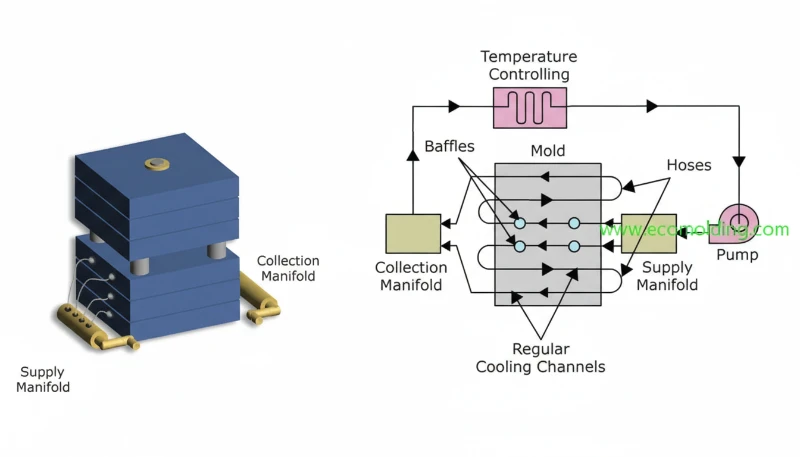
Our design rules for cooling channels: place channels within 10–15 mm of the cavity surface (closer is better, as long as structural integrity allows), space channels 25–35 mm apart for uniform heat extraction, maintain turbulent flow (Reynolds number >4,000) using 8–12 mm diameter channels with high flow rates, and always provide independent temperature control circuits for cavity and core sides. Differential temperature between cavity and core sides causes predictable bow or warp in the moulded part—something that can be corrected only by rebalancing the cooling, not by adjusting injection parameters.
게이트 설계는 사출 금형 품질에 어떤 영향을 줍니까?
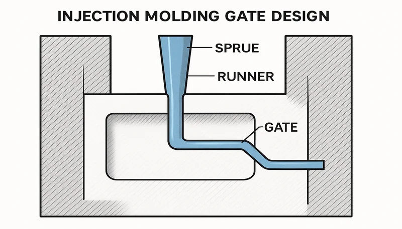
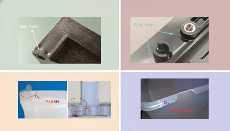
게이트 설계1에는 게이트 유형, 위치 및 치수가 포함됩니다. 이 세 변수는 용융 플라스틱이 캐비티에 들어가는 방식을 함께 결정하며, 그 결과 충전 패턴, 압력 분포, 웰드 라인2의 위치, 잔류 응력 상태 및 게이트 부위의 외관을 좌우합니다. 잘못된 게이트 설계는 거의 항상 금형강을 수정하거나 교체해야 하므로 가장 비용이 많이 드는 금형 오류 중 하나입니다.
당사는 다음 게이트 크기 지침을 따릅니다. 비정질 수지(ABS, PC, PS)의 게이트 깊이는 벽 두께의 50–75%, 반결정성 수지(PP, 나일론, POM)는 60–80%여야 합니다. 게이트가 너무 작으면 충분한 패킹 압력이 가해지기 전에 동결되어 싱크 마크, 보이드, 규격 미달 벽 두께가 발생합니다. 조기 동결을 방지하고 최대 압력으로 유동을 얇은 구간으로 유도하기 위해 게이트는 항상 가장 두꺼운 벽 구간에 배치합니다.
러너 시스템과 이젝션 시스템 설계는 부품 품질에 어떤 영향을 줍니까?
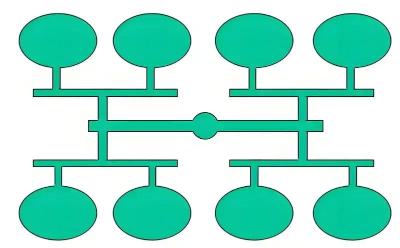
러너 시스템은 스프루에서 게이트까지 소재를 운반합니다. 잘못 설계된 러너는 소재를 낭비하고 과도한 압력 강하를 일으키며 다중 캐비티 금형에서 충전 불균형을 초래합니다. 콜드 러너 시스템에는 사다리꼴이나 반원형 단면보다 압력 강하가 가장 작고 열효율이 가장 높은 완전 원형 러너를 권장합니다. 대량 생산에서는 핫 러너 시스템3이 러너 스크랩을 완전히 없애고 복잡한 충전 제어를 위한 순차 밸브 게이트 제어를 지원합니다.
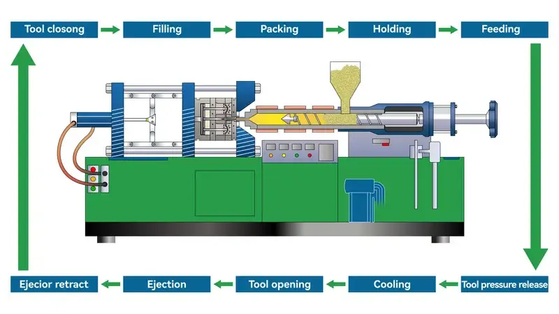
취출 시스템은 자국, 변형 또는 균열 없이 금형에서 부품을 제거하는 역할을 합니다. 이젝터 핀 위치는 부품의 가장 강한 영역(두꺼운 구간, 보스, 리브)에 취출력을 분산하고 얇은 외관면에 집중 하중을 가하지 않아야 합니다. 대부분 수지에서는 접촉 응력이 10 MPa 미만, 고속 취출 시 비충전 POM이나 유리섬유 충전 나일론 같은 취성 재료에서는 5 MPa 미만이 되도록 필요한 취출 면적을 계산합니다.
“파팅 라인에서의 플래시는 주로 과도한 사출 압력으로 인해 발생합니다.”False
과도한 사출 압력이 플래시를 유발할 수 있지만 가장 흔한 원인은 캐비티 투영 면적에 비해 형체력이 부족하거나 플라스틱이 빠져나가게 하는 마모 또는 손상된 파팅면입니다. 파팅면 상태가 양호하다면 적절히 계산된 형체력(일반적으로 투영 면적 제곱인치당 2–5톤)이 사출 압력과 관계없이 플래시를 방지합니다.
“교대 근무 및 작업자 간 공정 매개변수 안정성은 장기 생산 품질에 있어 금형 품질만큼 중요합니다.”True
잘 제작된 금형도 용융 온도, 사출 속도, 보압, 냉각 시간 등의 공정 매개변수가 안정적으로 유지될 때만 일관된 품질을 냅니다. 문서화된 공정 시트와 자동 매개변수 모니터링이 없으면 교대조 간 편차로 인해 금형 상태와 무관하게 일상적으로 5–15%의 품질 변동이 발생합니다.
기계 상태와 예방 유지보수는 장기적인 금형 품질을 어떻게 보호합니까?
장비 상태와 금형 유지보수는 양산 성형 작업에서 가장 간과되는 두 가지 품질 요인입니다. 당사 경험상 잘 설계되고 잘 제작된 금형이라도 마모된 장비에서 가동하면, 적절히 유지보수된 장비에서 가동하는 보통 수준의 금형보다 일관되게 낮은 성능을 보입니다. 장비 측 품질 요인에는 배럴 및 스크루 마모(쇼트 용량과 용융 온도 불균일 유발), 형체력 정확도(형체력이 부족하면 사출 중 파팅 라인이 열림), 타이바 평행도(형체력이 불균일하면 캐비티 압력 차이 발생)가 포함됩니다.
당사의 정밀 금형 예방 유지보수 일정은 다음과 같습니다. 매 50,000숏마다 냉각 채널을 청소하고, 이젝터 핀 간극을 검사하며, 파팅면 평탄도를 확인하고, 도장되지 않은 모든 표면에 방청제를 도포합니다. 매 250,000숏마다 중요 캐비티 치수를 CMM으로 표본 검사하고, 마모된 이젝터 핀을 교체하며, 열화된 캐비티 표면을 연마하고, 냉각 채널 유량을 재인증합니다. 모든 유지보수는 각 금형에 첨부된 로그에 기록합니다. 유지보수 로그가 없는 금형은 상태를 알 수 없는 툴로 취급하며 생산 승인 전에 전체 치수 인증을 받아야 합니다.
자주 묻는 질문
사출 성형 부품에서 싱크 마크의 가장 흔한 원인은 무엇인가요?
싱크 마크는 대개 보압이 부족하거나 게이트가 너무 일찍 고화되어 냉각 중 체적 수축을 재료가 보충하지 못할 때 발생합니다. 2차 원인으로는 너무 급격한 벽 두께 전이로 인한 차등 수축과 캐비티 표면에서 너무 멀어 열을 효율적으로 제거하지 못하는 냉각 채널이 있습니다. 대부분의 싱크 마크 문제는 보압 시간을 늘리고, 게이트 크기를 조정하거나, 두꺼운 부분에서 얇은 부분으로의 전이를 재설계하여 해결합니다.
벤트 설계는 사출 금형 품질에 어떤 영향을 줍니까?
벤팅이 부족하면 최종 충전 지점에 공기가 갇혀 번 마크(디젤 효과), 미충전, 취약한 부품 형상을 깨뜨릴 수 있는 높은 국부 압력이 발생합니다. 당사는 공기가 자연스럽게 갇히는 모든 위치에 깊이 0.01~0.02mm의 캐비티 벤트를 만들고 복잡한 부품에는 파팅 라인을 따라 25~50mm 간격으로 벤트를 추가합니다. 깨끗하고 크기가 적절한 벤트는 가장 저렴한 품질 개선책입니다. 예방 유지보수 주기에 맞춰 2시간 동안 벤트를 청소하면 수 시간의 문제 해결이 필요한 결함을 방지할 수 있습니다.
구배 각도는 취출 품질에 어떤 영향을 미치는가?
구배각이 부족하면 과도한 취출력이 발생해 취출 중 이젝터 핀 자국, 부품 변형 또는 균열이 생깁니다. 표준 최소 구배각은 텍스처 깊이 0.025 mm당 텍스처 표면 0.5–1°, 연마 표면 1–2°, 거친 또는 무광 표면 3–5°입니다. 마찰이 높은 유리 섬유 충전 수지는 표준 최소값에 0.5–1°를 추가합니다.
SPI 금형 분류 체계는 무엇이며 품질과 어떤 관련이 있는가?
SPI(Society of the Plastics Industry, 현재 Plastics Industry Association) 금형 등급 체계는 사출 금형을 Class 101(최고 품질, 1M+ shots, 경화강)부터 Class 105(저품질, <500 shots, 시제품 금형)까지 분류한다. 등급은 강재 경도, 냉각 채널 요구사항, 검사 표준을 규정한다. Class 102 금형은 H13 또는 420SS 강재를 사용하며 500,000–1 million shots에 대해 인증되고, Class 104 금형은 알루미늄 또는 P20을 사용하며 <100,000 shots 등급이다. 생산 요구사항에 맞는 금형 등급을 선택해야 장기 비용을 최소화하면서 일관된 부품 품질을 달성할 수 있다.
사출 성형에서 사출 속도는 표면 품질에 어떤 영향을 줍니까?
사출 속도는 러너와 게이트의 전단률을 제어하며, 이는 표면 광택, 웰드 라인의 가시성 및 플로 마크 형성에 영향을 줍니다. 사출 속도가 너무 느리면 충전이 완료되기 전에 소재가 냉각·고화되어 플로 마크와 웰드 라인이 발생합니다. 너무 빠르면 과도한 전단열이 발생하여 번 마크, 게이트 블러시 또는 제팅을 유발할 수 있습니다. 당사는 충전 전용 시험(95% 충전 상태의 숏숏)을 수행하여 부품이 눈에 띄는 유동 결함 없이 균일하게 충전되는 최적 속도 범위를 식별합니다.
캐비티 마모 후 사출 금형의 품질을 복원할 수 있습니까?
대부분의 경우 가능합니다. 경미한 캐비티 마모(치수 손실 0.02~0.1mm)는 동일한 강재 용접봉으로 TIG 용접한 뒤 경화 및 재연마하여 해당 영역을 보수하고 재가공할 수 있습니다. 심한 마모는 마모 표면을 제거하는 EDM 형조 가공, 소재 복원을 위한 용접, 전체 재가공이 필요합니다. 수리 가능성은 남은 강재 벽 두께를 기준으로 평가합니다. 수리 위치의 벽 두께가 8~10mm 미만인 캐비티는 일반적으로 수리 대신 교체합니다.
요약
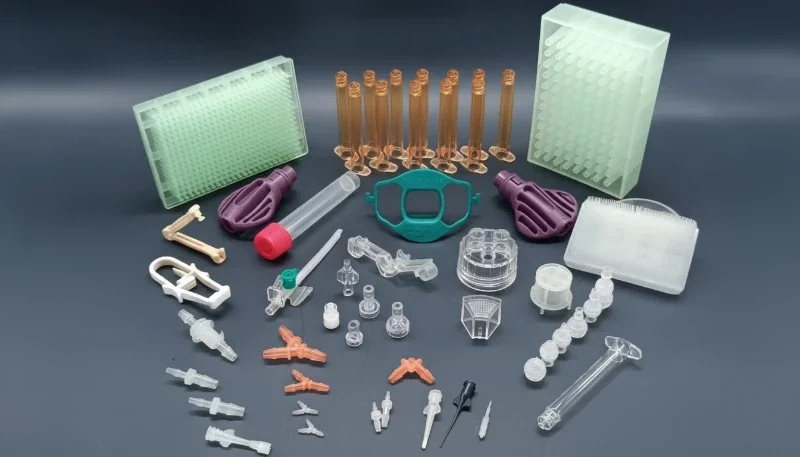
사출 금형 품질에 영향을 미치는 10가지 요소—원재료, 강재 선택, 냉각 설계, 게이트 설계, 러너 시스템, 이젝션 시스템, 파팅 표면 품질, 공정 매개변수, 기계 상태 및 유지 보수 일정—는 상호 연결된 시스템을 형성합니다. 우리 공장에서는 품질 문제를 시스템 문제로 취급합니다: 우리는 10가지 요소를 모두 감사하고 주요 원인과 기여 원인을 체계적으로 식별할 때까지 단일 요소가 책임이 있다고 가정하지 않습니다.
사출 금형 품질을 개선하려는 팀이라면 영향이 가장 클 가능성이 높은 세 가지 요인, 즉 원재료 입고 품질 관리, 냉각 시스템의 열 균일성 감사, 공정 매개변수의 문서화 및 모니터링부터 시작할 것을 권장합니다. 경험상 이 세 요인은 생산 품질 변동의 55~65%를 차지합니다. 이를 먼저 바로잡은 다음 해당 품질 문제와의 관련성이 높은 순서대로 나머지 요인을 검토하십시오. 자세한 개요는 사출 성형 완벽 가이드를 참조하십시오.
-
게이트 설계는 용융 플라스틱이 러너 시스템에서 금형 캐비티로 들어가는 입구의 구성, 위치 및 치수를 말합니다. 게이트 유형(에지, 핀, 터널, 핫 팁, 밸브)의 선택은 부품 외관, 치수 정확도 및 게이트 제거 용이성에 큰 영향을 줍니다. ↩
-
웰드 라인(니트 라인이라고도 함)은 캐비티 충전 중 서로 분리된 두 용융 플라스틱 유동 선단이 만나 융합되는 곳에 형성됩니다. 웰드 라인은 주변 소재보다 구조적으로 약하고(일반적으로 인장 강도가 10~30% 낮음), 특히 착색 수지나 유리섬유 충전 수지를 사용한 부품 표면에 선으로 보일 수 있습니다. ↩
-
핫 러너 시스템은 금형에 설치되는 가열식 매니폴드와 노즐 어셈블리로, 생산 사이클 내내 러너 채널의 플라스틱을 용융 상태로 유지하여 기존 콜드 러너 시스템에서 발생하는 고형 러너 폐기물을 없앱니다. 핫 러너 시스템은 소재 효율과 사이클 시간을 개선하지만 더 많은 금형 투자와 정밀한 온도 제어가 필요합니다. ↩
ZetarMold 엔지니어링 팀에서 경쟁력 있는 가격, DFM 피드백, 생산 일정을 받아 보십시오.
무료 견적 요청 → 자세한 개요는 사출 성형 완벽 가이드를 참조하십시오.