 콘텐츠로 건너뛰기

An 사출 성형 기계는 구동 방식과 방향에 따라 분류됩니다. 사출 금형, and ejects a finished part every few seconds. Whether you are molding medical device housings or automotive clips, understanding how the machine works is the difference between a stable process and weeks of costly defects. This guide breaks down every major subsystem, the step-by-step molding cycle, common failure modes, and what actually matters when you are selecting machine tonnage for a new project.
- An injection molding machine has two core units: injection (melts and pushes plastic) and clamping (holds and opens the mold).
- The reciprocating screw is the single most important component — it plasticizes, meters, and injects material in one cycle.
- Clamping force must exceed the projected cavity area × peak melt pressure, or the mold will flash.
- Modern all-electric machines offer 30–50% energy savings over hydraulic equivalents, with better shot-to-shot repeatability.
- Understanding machine specifications (shot size, tie-bar spacing, platen size) is critical before investing in tooling.
What Are the Main Components of an Injection Molding Machine?
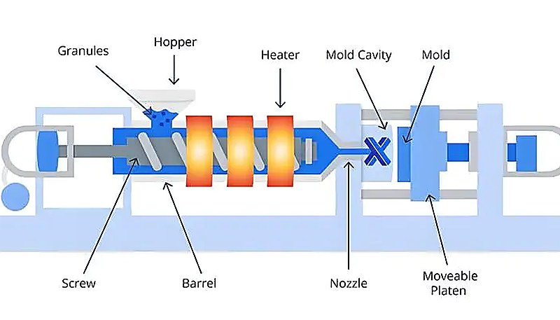
Every injection molding machine, regardless of brand or vintage, consists of two primary units bolted to a common base frame. The 주입 장치 handles everything related to melting and delivering the plastic: the hopper, barrel, reciprocating screw1, heater bands, and nozzle. The 클램핑 장치 handles everything related to the mold: the fixed and moving platens, toggle or hydraulic clamping mechanism, ejector system, and tie bars. Bridging the two are the machine controls — a PLC or dedicated controller that coordinates temperature zones, injection pressure, screw speed, holding pressure, and timing.
In practice, when something goes wrong on a production floor, the first question an experienced process engineer asks is which unit is causing the problem — and that comes down to knowing these components cold.
How Does the Injection Unit Work?
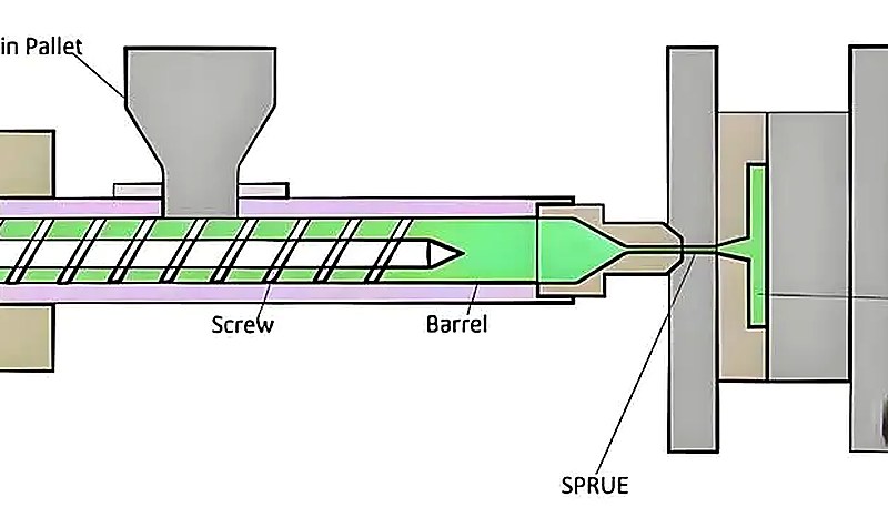
사출 유닛은 원료 변형이 발생하는 곳입니다. 플라스틱 펠릿이 호퍼에서 배럴로 떨어지며, 왕복 스크류가 회전하여 스크류 끝 앞에 용융 폴리머 쿠션을 형성합니다. 배럴은 일반적으로 3~5개의 온도 구역으로 구성된 히터 밴드로 둘러싸여 있으며, 재료를 목표 용융 온도로 가져옵니다. 동시에 스크류 회전은 마찰 열을 통해 실제 대부분의 열을 발생시키며, 나일론이나 POM 같은 부분 결정 재료의 경우 총 열 입력의 60–80%를 제공합니다.
Once enough melt has accumulated (the shot size), the screw stops rotating and acts as a plunger. It pushes forward under high pressure — often 1,000 to 2,000 bar — forcing the melt through the nozzle, into the sprue, runners, and finally the mold cavities. The 유지 압력 phase follows immediately, packing additional material into the cavity to compensate for volumetric shrinkage as the part cools. This packing phase is where a lot of part quality is determined: too little pressure and you get sink marks and voids; too much and you 플래시2 the mold or overpack, causing dimensional issues and high residual stress.

What Is the Clamping Unit and Why Does Tonnage Matter?
The clamping unit and why does tonnage matter is defined by the function, constraints, and tradeoffs explained in this section. The clamping unit keeps the mold halves locked together with enough force to resist the injection pressure trying to push them apart. If 클램핑 력3 is insufficient, the mold separates slightly and molten plastic escapes — that is 플래시, and it ruins parts. Clamping force is measured in tons or kilonewtons.
A rough rule of thumb: take the projected area of all cavities in cm², multiply by the injection pressure in kg/cm², then add a 10–20% safety margin. For example, a part with 200 cm² projected area at 600 kg/cm² needs at minimum a 120-ton machine — most engineers would spec a 150-ton to be safe.
There are three main clamping mechanisms. Toggle systems use a mechanical linkage that provides a self-locking advantage — fast open/close speeds and energy efficiency, but the clamping force varies slightly with mold height. Direct hydraulic clamps use a large-bore cylinder for consistent force regardless of mold thickness, making them popular for deep-draw or high-precision molds. Two-platen machines separate the clamping and locking functions, reducing the machine footprint significantly — you will see these on large-tonnage machines (1,000+ tons) where floor space is a real constraint. In our shop, we run machines from 90T all the way to 1,850T, and the choice between toggle and hydraulic depends on the part geometry and tolerance requirements.
“동일한 톤 범위에서 토글 클램프는 일반적으로 직접 유압 클램프보다 사이클 시간이 빠릅니다.”True
Toggle linkages achieve full clamping force through mechanical advantage, allowing rapid open/close strokes. Hydraulic clamps must build pressure in a large cylinder, which takes more time per stroke.
“100톤 사출 성형기는 플레이트 치수 내에 들어가는 모든 제품을 안전하게 성형할 수 있습니다.”False
Tonnage refers to clamping force, not platen size. A large-area thin-wall part can require far more clamping force than a small thick-wall part — you must calculate based on projected cavity area × peak cavity pressure.
How Does the Full Molding Cycle Work Step by Step?
이 섹션은 전체 성형 사이클이 단계별로 작동하는 방식과 비용, 품질, 시기 또는 조달 위험에 미치는 영향을 설명합니다. 사출 성형 단계 사출 성형은 네 가지 주요 단계를 포함하며, 각 단계는 제품 품질에 영향을 미칩니다. 실제로 기계 내부에서 순서대로 발생하는 과정은 다음과 같습니다:
1. Clamping and Mold Closing. The clamping unit drives the moving platen forward until the mold halves meet. The machine builds full clamping force — this can take 0.5 to 3 seconds depending on machine size and mechanism. The mold must be fully closed and locked before injection begins; safety interlocks prevent injection otherwise.
2. Injection and Filling. The screw pushes forward as a plunger, forcing molten plastic through the nozzle, sprue, runner system, and into the cavities. Fill speed is critical — too fast and you trap air (burns, jetting); too slow and the melt front freezes before the cavity is complete (short shots). Fill time for a typical consumer-electronics housing might be 0.3 to 1.5 seconds.
3. Packing and Holding. Once the cavity is volumetrically full, the machine transitions to holding pressure. The screw maintains forward pressure, pushing more material into the cavity as the plastic cools and shrinks. This phase typically lasts 2–15 seconds and directly controls part weight, dimensional accuracy, and sink-mark severity. The gate must remain open during this entire phase; once the gate freezes, additional pressure has no effect.
4. Cooling and Ejection. The part continues to cool inside the mold until it is rigid enough to eject without deformation. Cooling time dominates the overall cycle — often 50–70% of total cycle time for thick-wall parts. Meanwhile, the screw retracts and begins rotating to plasticize material for the next shot. Once the timer expires, the mold opens, the ejector pins push the part off the core, and the cycle restarts. A well-optimized cycle for a simple PP closure might run in 8–12 seconds; a large automotive interior panel could take 45–60 seconds.
What Types of Injection Molding Machines Exist?
Machines are classified by both drive type and orientation. 유압에서 올일렉트릭 및 하이브리드 드라이브로의 전환이 전 세계적으로 가속화되고 있습니다. 서보 모터는 폐쇄 루프 위치 제어를 제공하여 사출 스트로크의 매 밀리초마다 나사가 정확히 어디에 있는지 기계가 알 수 있게 합니다. 이로써 과학적 성형이 가능해집니다 — 속도 프로파일을 5~10개 세그먼트로 설정하고 샷마다 동일한 곡선을 정확히 구현할 수 있습니다. 대량 의료 및 전자 제품 생산에서 이러한 반복성은 단순히 바람직한 요소가 아니라 규제 요구사항입니다. machines have been the industry standard for decades — they use hydraulic oil to power the clamp, injection, and screw drives. They are robust, relatively inexpensive per ton, and handle high-tonnage applications well. Their downsides: higher energy consumption, oil temperature sensitivity, and less precise shot-to-shot repeatability compared to electric machines.
All-electric machines use servo motors for every axis — injection, clamping, screw rotation, and ejection. They consume 30–50% less energy (no hydraulic pump running continuously), offer superior positioning accuracy (±0.01 mm screw position repeatability is common), run cleaner (no oil), and are quieter. The trade-off is higher upfront cost and limited tonnage range — most top out around 800 tons, though some manufacturers now offer electric machines up to 1,500 tons.
하이브리드 machines combine the best of both: servo-electric drives for injection and screw plastification (where precision matters most) with hydraulic clamping (where brute force at lower cost matters). In our facility we run all three types — hydraulic for large structural parts up to 1,850T, all-electric for precision medical and electronics components, and hybrid for mid-range applications where the economics balance out.
“하이브리드 기계는 전동급 사출 정밀도를 달성하면서 유압 클램프 비용 이점을 유지할 수 있습니다.”True
By using servo motors for injection and plastification where shot-to-shot precision matters, and hydraulic systems for clamping where force per dollar is key, hybrids split the optimization effectively.
“전동 기계는 항상 유압 기계보다 더 좋은 품질의 제품을 생산합니다.”False
All-electric machines offer better repeatability and energy efficiency, but part quality is primarily determined by mold design, material selection, and process parameters. A well-tuned hydraulic machine can produce identical quality for many applications.
How Do You Select the Right Machine for a Project?
이 섹션은 프로젝트에 적합한 기계를 선택하는 방법과 비용, 품질, 시기 또는 조달 위험에 미치는 영향을 설명합니다. 적합한 사출 성형기를 선택하려면 제품 요구 사항에 대해 클램프력, 사출 크기, 플레이트 크기 및 티바 간격, 개방 스트로크, 사출 속도 등 다섯 가지 파라미터를 확인해야 합니다. 이 중 하나를 놓치면 선택된 프레스에서 금형을 사용할 수 없게 될 수 있습니다.
먼저, 투영 면적과 재료별 캐비티 압력을 기준으로 클램핑력을 계산합니다. 둘째, shot size: 기계의 지정 사출 용량은 제품 총 무게와 런너 시스템을 포함해야 하며, 이상적으로 지정 용량의 30-70%에서 운영되어야 합니다. 세 번째로, platen size and tie-bar spacing: the mold must physically fit between the tie bars and on the platen. Fourth, opening stroke: there must be enough daylight to eject the deepest part of the mold. Fifth, injection speed and pressure: 얇은 벽 제품은 높은 사출 속도(200-500 mm/s)가 필요하며, 두꺼운 벽 제품은 지속적인 홀딩 압력이 필요합니다.
공장 DFM 검토 경험에서 많은 sourcing 팀은 톤수만 고려하고 사출 크기와 티바 간격을 간과한 후 금형이 맞지 않거나 기계가 완전 사출을 제공할 수 없다는 것을 발견합니다. 따라서 금형 결정 전 성형사의 DFM 검토는 필수입니다. ZetarMold에서는 우리 팀이 금형 제작 전 모든 프로젝트를 다섯 가지 파라미터 모두로 검토합니다. 90톤부터 1,850톤까지 47대의 기계와 400+ 재료 경험을 통해 우리는 제품에 적합한 기계를 선택할 수 있습니다 — 반대 방향으로는 아닙니다.
What Are Common Machine Faults and How Do You Troubleshoot Them?
Common machine faults and how do you troubleshoot them are the main categories or options explained in this section. Even well-maintained machines develop issues. Here are the problems we see most often on the production floor, and what actually causes them.
| Fault | Likely Root Cause | Corrective Action |
|---|---|---|
| Temperature instability | Thermocouple degradation or loose heater band connection | Replace thermocouple; verify heater band resistance and tightness |
| Short shots (incomplete fill) | Insufficient injection pressure, blocked gate, or worn screw/check ring | Increase injection pressure; inspect gate and screw tip assembly |
| Flash on parting line | Clamping force too low, or mold faces worn/damaged | Verify tonnage; reseat mold; inspect parting-line condition |
| Screw slip (cannot build back pressure) | Worn barrel/screw, or material contamination at feed throat | Measure barrel/screw clearance; clean feed throat; check material |
| Inconsistent part weight | Worn check ring (non-return valve) allowing melt to leak back | Replace check ring — this is the #1 cause of shot-to-shot variation |
| Hopper bridging | Material pellets sticking together due to moisture or static | Install hopper agitator; ensure material is properly dried |
스크류 끝에 있는 역류 방지 밸브는 스크류 사출 성형기 는 마모 부품입니다 — 사출 시 역류를 방지합니다. 마모되면 사출량이 불규칙해지고 모든 제품의 무게가 달라집니다. 치수 변동을 추적하고 온도 및 재료 문제를 이미 배제한 경우, 스크류를 분리하여 체크 링 간극을 측정하십시오. 우리 공장에서는 예방적 유지보수 과정의 일부로 체크 링을 검사하며, 이는 생산에 영향을 미치기 전에 많은 품질 문제를 제거합니다.
How Are Injection Molding Machines Evolving?
The machine landscape is changing fast, driven by three forces: energy costs, Industry 4.0 connectivity, and multi-material capability demands.
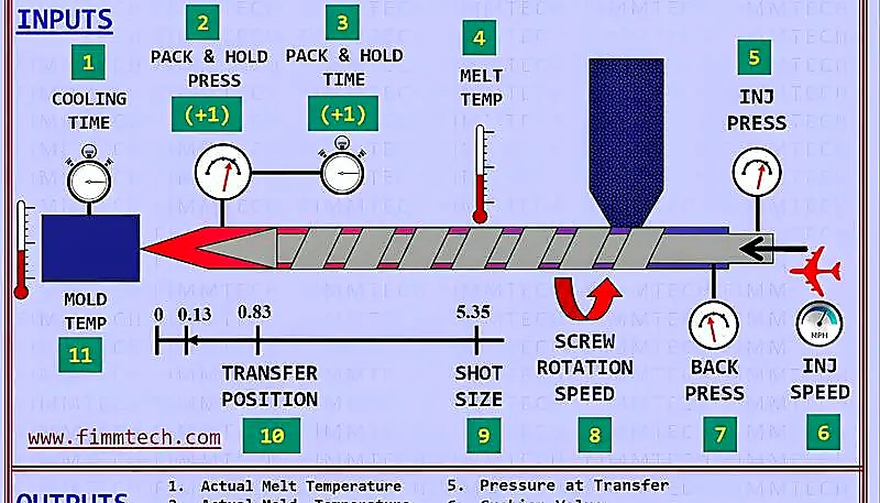
Servo-driven systems. The shift from hydraulic to all-electric and hybrid drives is accelerating globally. Servo motors provide closed-loop position control, meaning the machine knows exactly where the screw is at every millisecond of the injection stroke. This enables scientific molding — you can set a velocity profile in 5–10 segments and hit the same curve shot after shot. For high-volume medical and electronics production, this repeatability is not a nice-to-have; it is a regulatory requirement.
Industry 4.0 integration. Modern machines expose real-time data — cavity pressure curves, screw position, barrel temperatures, cycle counts — via OPC-UA or MQTT protocols. This data feeds into SPC dashboards and predictive maintenance systems. Instead of reacting to defects, you get alerts when a process parameter starts drifting before any bad parts are produced. We have started deploying inline quality monitoring on critical production runs, and the reduction in scrap rates has been significant.
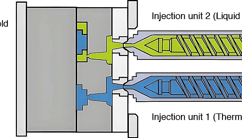
Multi-material and multi-component molding. Machines with two or more injection units (like our three new dual-shot machines added in 2024) can mold hard and soft materials together in a single cycle — think of a power tool handle with a rigid PP core and a TPE overmold grip. This eliminates secondary assembly operations and reduces total manufacturing cost. The machine coordination is complex (rotary tables, core-pull sequences, independent barrel temperatures), but the production efficiency gain is substantial.
ZetarMold에서는 유압, 전동 및 하이브리드 플랫폼의 90톤부터 1,850톤까지 총 47대의 사출 성형기를 운영합니다. 우리 엔지니어링 팀은 기계 성능 데이터를 정기적으로 평가하여 사이클 파라미터를 최적화합니다 — 2025년에는 우리 기계 군 전체의 공정 최적화로 대량 자동차 프로그램의 평균 사이클 시간을 12% 단축했습니다.
결론
Understanding how an injection molding machine works is not academic — it directly impacts part quality, tooling longevity, and production cost. The machine is a system of interconnected subsystems: the injection unit must deliver consistent melt temperature and shot volume, the clamp must hold the mold with sufficient force, and the controls must coordinate every parameter with sub-second precision. When any of these elements drift, defects follow.
새로운 성형 프로젝트를 지정하는 엔지니어와 조달 팀에게 실질적인 요점은 다음과 같습니다: 성형사의 엔지니어링 팀을 초기에 참여시키고, 선택된 기계가 모든 다섯 가지 핵심 파라미터(톤수, 사출 크기, 플레이트 크기, 개방 스트로크, 사출 성능)와 일치하는지 확인하며, 예방적 유지보수 — 특히 체크 링 검사 및 배럴/스크류 측정 — 에 투자하여 일관된 품질의 기초를 마련하십시오.
자주 묻는 질문
What is the typical cycle time for an injection molding machine?
Cycle time depends heavily on part thickness, material, and mold design. A thin-wall PP closure might run in 5–8 seconds on a high-speed machine optimized for packaging. A standard consumer-electronics housing typically runs in 15–25 seconds with adequate cooling. A large automotive interior panel with deep ribs can take 45–60 seconds or more. Cooling time is typically 50–70% of the total cycle, so reducing wall thickness and optimizing cooling channel layout are the most effective ways to shorten cycle time. Machine type also matters — all-electric machines often achieve faster cycle times due to quicker clamp strokes and more precise holding-pressure cutoff.
How much clamping force does my part need?
A practical formula for estimating clamping force: multiply the projected cavity area in cm² by the cavity pressure in kg/cm², add a 15% safety margin, and divide by 1,000 to get tons. Cavity pressure varies significantly by material — typically 200–400 kg/cm² for easy-flow materials like PP and PE, and 600–800 kg/cm² for engineering resins like PC, POM, or glass-filled nylon. Multi-cavity molds require summing the projected area across all cavities. Always round up to the nearest standard machine size, and remember that actual cavity pressure is influenced by gate size, fill speed, melt temperature, and part geometry.
What is the difference between hydraulic and all-electric injection molding machines?
Hydraulic machines use oil-driven pumps and cylinders to power the clamp, injection, and screw drives — they are cost-effective per ton and handle high-tonnage applications well, typically up to 4,000+ tons. All-electric machines use servo motors for every axis, offering 30–50% energy savings, superior shot-to-shot repeatability with ±0.01 mm screw positioning, cleaner operation with no hydraulic oil, and quieter running conditions. The trade-off is higher upfront purchase cost and limited availability above 800–1,000 tons. Hybrid machines combine servo injection with hydraulic clamping for a balanced solution.
What causes flash in injection molding?
Flash occurs when the clamping force is insufficient to keep the mold halves fully sealed against the injection pressure pushing them apart. Other contributing causes include worn or damaged parting-line surfaces on the mold, excessive injection pressure or speed that spikes cavity pressure beyond the clamp capacity, mold deflection under load (especially in large-area molds), and uneven mold seating on the platens. The corrective approach starts with verifying actual clamping force versus the calculated requirement, then inspecting the mold parting line for wear, and finally optimizing the injection pressure and speed profiles to reduce the peak cavity pressure.
How do you maintain an injection molding machine?
Critical maintenance items for injection molding machines include inspecting and replacing check rings and screw tips (these are wear items that directly affect shot consistency), verifying barrel-to-screw clearance annually to detect wear before it impacts melt quality, calibrating thermocouples and pressure transducers to ensure process data is accurate, changing hydraulic oil and filters on the manufacturer recommended schedule, lubricating toggle pins and tie bars to prevent galling and ensure smooth clamp operation, and inspecting heater bands for resistance drift or physical damage that could cause temperature zones to deviate.
What is a reciprocating screw in injection molding?
The reciprocating screw is the central component of the injection unit and serves a dual purpose within each molding cycle. During the plastification phase, it rotates inside the heated barrel to mix, compress, and melt the raw polymer pellets through a combination of external heater band input and internal shear friction — typically providing 60–80% of total heat for semi-crystalline materials. During the injection phase, the screw stops rotating and moves forward as a plunger, pushing the accumulated melt through the nozzle and into the mold. A non-return valve at the screw tip prevents backward melt flow during this forward stroke.
What is scientific molding?
Scientific molding is a systematic, data-driven methodology that relies on cavity pressure sensors, screw position monitoring, and decoupled process stages — separating fill, pack, and hold into independently controlled phases — to establish a robust and repeatable manufacturing process. Rather than adjusting machine settings by intuition, scientific molding uses pressure curves and statistical analysis to define optimal parameters that produce consistent parts regardless of machine, operator, or environmental variation. It requires machines with closed-loop servo control and is increasingly standard in medical, automotive, and electronics production where regulatory compliance demands documented process stability.
Can injection molding machines process all types of plastics?
Most thermoplastic materials can be processed on standard injection molding machines, ranging from commodity resins like PP, PE, and PS to engineering plastics including PA, PC, POM, and PBT, up to high-performance polymers such as PEEK, PPS, and LCP. However, each material category has specific requirements for barrel temperature range, screw design geometry including compression ratio and L/D ratio, and nozzle type. Thermosets and rubber elastomers require specialized machines with different barrel designs and temperature profiles. Materials that are highly moisture-sensitive may also require machines equipped with vented barrels or dedicated drying systems integrated with the feed throat.
-
reciprocating screw: A reciprocating screw is a component that alternates between rotational movement for plasticizing material and linear forward movement for injecting the melt into the mold cavity. ↩
-
flash: flash refers to is excess plastic that escapes from the mold parting line during injection, typically caused by insufficient clamping force or mold wear. ↩
-
clamping force: Clamping force is the pressure applied by the machine to keep the mold closed during injection, measured in tons or kilonewtons, and must exceed the total cavity pressure multiplied by the projected area of the part. ↩


