 콘텐츠로 건너뛰기

PP 및 PE 기판—기본 선택 secondary injection1 molding process where a soft thermoplastic elastomer (TPE) or TPU is molded over a rigid plastic substrate2 in a two-step sequence, creating a permanently bonded multi-material part in a single fixture. The additional mold cost comes from the precision needed to position and seal the first-shot substrate during the second shot—vacuum channels, shut-off surfaces, and tighter tolerances that prevent flash and delamination.
그러나 사용자 경험, 브랜드 차별화, 인체공학적 안전이 중요한 대량 생산의 경우, 오버몰딩은 패드 프린팅, 접착 필름, 후조립 코팅 등이 따라올 수 없는 이점을 제공합니다. 본 가이드는 ZetarMold의 상하이 시설에서 지난 20년 이상 오버몰드 생산을 운영하며 얻은 경험을 바탕으로 재료 선택, 금형 설계 규칙, 공정 매개변수, 일반적인 결함을 포함한 전체 오버몰딩 워크플로를 안내합니다.
- Overmold is a secondary injection molding process that bonds soft TPE/TPU over rigid plastic substrates.
- Mold costs are 25–40% higher than single-material molds due to substrate positioning and sealing requirements.
- Substrate and overmold materials must have matching chemical compatibility or require tie layers for reliable adhesion.
- Processing temperatures must differ by at least 20°C to avoid melting the substrate during the second shot.
- Overmolding eliminates secondary decoration operations and produces permanent, scratch-resistant graphics.
What Is Overmolding?
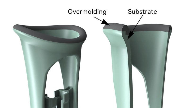
Overmolding is a specialized injection molding technique where two different materials are molded in sequence to create a single, integrated part. The process begins with a first shot that produces the rigid substrate—a structural component typically made from ABS, polycarbonate (PC), or polypropylene (PP). This substrate is then transferred, either by robot or manually, into a second cavity where the overmold material is injected. During the second injection, the molten overmold material chemically bonds to the substrate surface, creating a permanent interface that resists peeling and separation under normal use conditions.
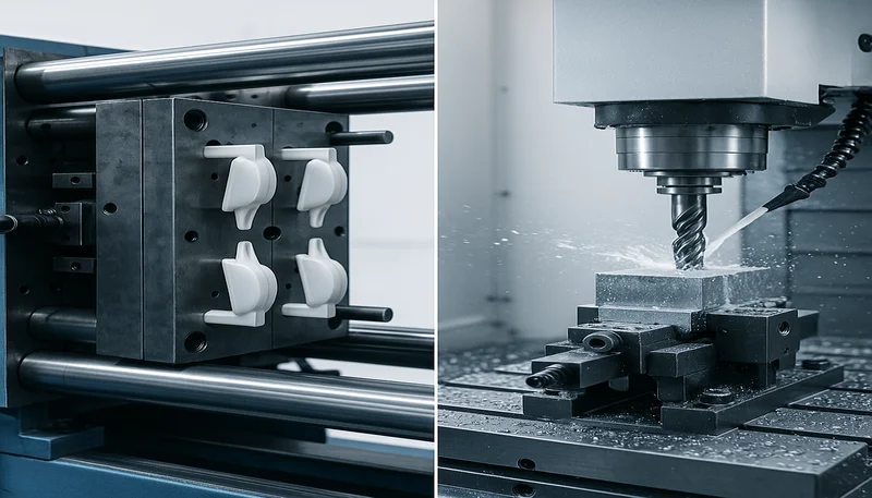
The technology originated in the consumer electronics industry for power tool handles and toothbrush grips, where ergonomics and slip resistance directly impact user satisfaction. Since then, overmolding has expanded into medical device housings, automotive interior components, and consumer product casings. If you have held a drill with a soft-touch grip or a smartphone case with a rubberized bumper that never peeled off, you have experienced overmolding in action.
Compared with standard 사출 성형 followed by secondary decoration methods like pad printing or adhesive labeling, overmolding produces a part where the functional surface is integral to the component structure. There is no adhesive layer that can degrade over time, no ink that can wear off from abrasion, and no post-mold assembly steps that add cycle time and cost. The trade-off is higher tooling investment and more complex process setup, but the resulting part quality and durability justify the investment for most volume-produced consumer and industrial products.
“오버몰드된 부품은 부품을 파괴하지 않고는 구성 재료로 분리할 수 없습니다.”True
The second injection creates a chemical bond between the substrate and overmold material that is as strong or stronger than the bulk material itself. Attempting to peel or separate the two materials will typically fracture one or both before the interface fails.
“기존 금형을 수정하지 않고 오버몰드 색상이나 재질을 변경할 수 있습니다.”False
The overmold cavity geometry is fixed once the mold is built. Changing overmold materials—especially switching between different durometers or material families like TPE versus TPU—often requires gate, vent, or temperature profile adjustments to maintain bond quality. A true overmold tool change requires engineering qualification, not just swapping material at the machine.
How Does the Overmolding Process Work?
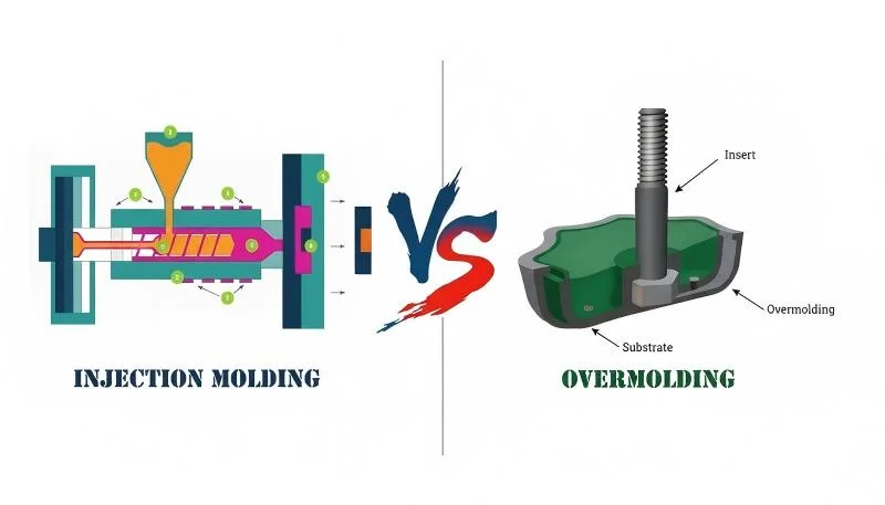
오버몰딩 공정은 이 섹션에서 설명하는 단계와 설정을 통해 작동하는 제어된 공정 순서입니다. 오버몰딩은 투컬러 사출 성형과 결정적인 차이점이 있는 별개의 순서를 따릅니다. 두 샷은 동일한 사이클에서 동시에 이루어지는 것이 아니라 별도의 금형이나 다른 캐비티에서 발생합니다. 이러한 분리는 재료 선택과 부품 형상에 있어 훨씬 더 많은 유연성을 허용하지만, 동시에 엄격하게 제어해야 하는 취급 및 위치 지정 문제를 야기합니다. 다음은 기판 생산부터 완성 부품 이젝션까지의 오버몰딩 워크플로우에 대한 완전한 분석입니다.
Step 1: First Shot—Substrate Molding
The process begins with molding the rigid substrate in a conventional single-material injection mold. This mold produces the core structural component—the hard plastic body that will receive the overmold in the second shot. At this stage, the substrate must meet critical quality criteria: dimensional accuracy within ±0.05 mm on surfaces that will interface with the overmold cavity, consistent cooling to avoid warpage that would prevent proper seating in the second mold, and surface preparation such as mold temperature control to ensure the overmold material can bond reliably during the secondary injection.
Step 2: Substrate Transfer
After the substrate is ejected from the first mold, it must be transferred to the second mold cavity. In manual operations, this is done by hand by operators using gloves or specialized grippers to avoid contaminating the bonding surface. In fully automated production, a robot arm equipped with vacuum grippers or mechanical clamps picks up the substrate and places it into precise positioning features in the overmold cavity. Positioning accuracy is critical—offsets greater than 0.1 mm can cause uneven overmold thickness, flash at the bond line, or complete failure of the substrate to seat correctly in the second cavity.
Step 3: Substrate Positioning and Sealing
The overmold cavity includes precision features that align and seal the substrate before the second injection begins. These features include locating pins or datum surfaces that match corresponding features on the substrate, shut-off surfaces that create a seal between the cavity and the exposed substrate surfaces, and vacuum channels in some advanced designs that pull the substrate flat against the cavity wall. Proper positioning ensures the overmold material fills evenly around the substrate without creating voids, thin spots, or areas where the substrate is not fully encapsulated. In our factory, we have found that inadequate substrate sealing accounts for over 60% of overmold scrap during production qualification, making it the single most critical design parameter.
Step 4: Secondary Injection
With the substrate positioned and sealed, the overmold material is injected into the cavity. The injection temperature and speed are controlled precisely to achieve two goals simultaneously: melting the surface of the substrate to create a chemical bond while avoiding excessive heat that would distort or melt through the substrate completely. The tie layer3 on the substrate surface activates within seconds of contact with the molten overmold material, creating a molecular bond. Injection parameters vary significantly between material pairs—for example, TPE over PP requires 190–210°C at moderate speed, while TPU over PC may need 230–250°C with a slower fill to prevent thermal degradation of the PC substrate.
Step 5: Packing, Cooling, and Ejection
After cavity fill, holding pressure is applied to compensate for shrinkage and ensure the overmold material fully conforms to the cavity geometry. The cooling phase solidifies both the overmold material and the bond interface. Cooling times for overmolded parts are typically 15–25% longer than single-material parts of equivalent size because the overmold material acts as a thermal insulator on the substrate side, slowing heat extraction. Once cooled, the mold opens and the finished part is ejected. The entire substrate transfer-to-ejection sequence typically adds 2–4 seconds to cycle time compared to a standard molding operation.
| 매개변수 | Standard Injection Molding | 오버몰딩 |
|---|---|---|
| Cycle time (typical part) | 20–30 s | 25–35 s |
| Mold cost vs baseline | Baseline | +25–40% |
| Secondary operations | Often required (printing, coating) | Eliminated |
| Material options | Single material per part | Multiple materials integrated |
| Tool complexity | 표준 | High (positioning, sealing) |
What Materials Work for Overmolding?
Material compatibility is the single most critical factor in overmolding success. The substrate and overmold materials must bond chemically during the secondary injection, which means their surface energies, chemical structures, and processing temperatures must be carefully matched. Selecting incompatible materials leads to delamination—the most frustrating overmold defect because it may not appear until weeks after production during thermal cycling or mechanical stress testing.
PP and PE Substrates—The Default Choice
오버몰드 그립 표면을 통과하는 핀
ABS and PC Substrates—Engineering Grade
ABS and polycarbonate (PC) substrates require more careful material pairing because of their higher processing temperatures and different surface chemistries. ABS typically bonds well to TPE overmolds when the melt temperature is controlled between 220–240°C, while PC may require specialty TPU formulations with higher thermal stability. The bonding window is narrower than with PP-based systems, and the risk of substrate distortion during the secondary injection increases significantly. We run ABS and PC overmold projects regularly for electronics and medical device clients, but every one required material compatibility testing before tooling commitment—often adding 2–3 weeks to the qualification timeline.
TPE, TPU, and Silicone Overmold Materials
열가소성 엘라스토머(TPE)와 열가소성 폴리우레탄(TPU)은 유연성, 내구성, 가공성의 균형 덕분에 오버몰드 재료 시장을 지배하고 있습니다. TPE는 소프트 터치 감촉과 적당한 내마모성이 충분한 소비재 제품의 기본 선택입니다—더 낮은 온도에서 가공되며 대부분의 경질 플라스틱에 안정적으로 접합됩니다. TPU는 우수한 내마모성과 내화학성을 제공하여 공구 손잡이, 의료 기기 그립, 오버몰드 표면이 반복적인 마모를 겪는 응용 분야에서 선호되는 재료입니다. 액상 실리콘 고무(LSR) 오버몰딩은 가능하지만 일반적이지 않은데, 이는 전용 LSR 가공 장비와 상당히 다른 금형 설계가 필요하기 때문입니다—일반적으로 실리콘의 생체 적합성과 열적 안정성이 필수인 의료 또는 식품 접촉 응용 분야에서만 정당화됩니다.
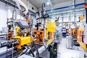
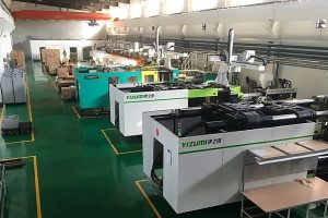
ZetarMold에서는 90톤에서 1850톤에 이르는 47대의 사출 성형기를 통해 사출 금형 역량을 유지하고 있으며, 재료 라이브러리는 오버몰딩을 위한 특수 TPE 및 TPU 배합을 포함한 400종 이상의 수지를 포괄합니다. 20년 이상의 경험과 8명의 수석 엔지니어가 모든 오버몰드 검증을 감독함으로써, 우리는 사실상 모든 일반적인 기재-오버몰드 조합을 테스트하고 신뢰성 있게 작동하는 공정 창을 문서화했습니다. 120명 이상의 생산 작업자와 30명 이상의 영어를 구사하는 프로젝트 관리자는 오버몰드 금형에 대한 기술 사양이 번역 과정에서 손실되지 않도록 보장합니다—이는 팀이 injection molding supplier sourcing guide 전담 국제 엔지니어링 팀 없이.
In our Shanghai factory, we run 47 injection molding machines from 90T to 1850T and use an in-house mold manufacturing facility that supports 100+ mold sets per month. For overmolding, that matters because substrate shut-off, sealing steel, and second-shot trials can be checked by tooling and production teams before a design reaches mass production.
What Design Rules Govern Overmold Tooling?
이 섹션은 오버몰드 금형 설계 규칙과 이로 인한 비용, 품질, 시기 또는 조달 리스크에 대한 영향에 관한 것입니다. 오버몰드 금형은 표준 사출 금형 설계 in several critical ways. These differences are not optional enhancements—they are mandatory features that determine whether an overmold project runs reliably at low scrap rates or becomes a continuous production nightmare. Here are the design rules that separate a functional overmold tool from an expensive paperweight.
Substrate Sealing and Shut-Off Surfaces
The overmold cavity must seal completely around the substrate to prevent flash—the unwanted thin film of plastic that escapes the cavity at gaps. Shut-off surfaces are designed with 0.05–0.10 mm clearance from the substrate surface, tight enough to prevent flash but wide enough to avoid rubbing or marring the substrate during seating. The most critical sealing surfaces are those that contact edges and corners of the substrate, as these are the points where flash is most likely to form. In our experience, insufficient shut-off design is the leading cause of overmold scrap rates exceeding 10% during initial production runs.
Positioning Features and Tolerances
The overmold cavity includes locating pins, datum surfaces, and sometimes mechanical clamps that hold the substrate in precise position during the secondary injection. These features must maintain ±0.05 mm positioning accuracy to ensure the overmold material flows evenly around the substrate. If the substrate shifts even slightly during injection, the overmold thickness will vary, creating weak points in the part where the overmold is too thin or flash where the cavity opens up too much. Positioning tolerance is cumulative with substrate dimensional variation, which means the first-shot mold must produce parts to tighter specifications than a conventional single-material mold—typically ±0.025 mm on surfaces that interface with the overmold cavity.
Gate Location and Flow Design
The overmold gate must be positioned to direct flow such that the molten material sweeps across the substrate without creating weld lines that cross critical bond surfaces. In standard molding, gate placement optimizes for fill pattern and cosmetic appearance. In overmolding, gate placement must also avoid jetting melt directly onto the substrate surface, which can cause local melting or distortion. The gate vestige should land on a non-critical overmold surface whenever possible, or on the substrate only if the material pair can withstand the thermal shock without degradation. We have seen projects where improper gate design caused visible burn marks on the substrate surface—requiring a complete mold redesign after the first trial.
배출 시스템 설계
Ejector pins cannot pass through the overmold material in ways that would leave visible marks or compromise the bond. This constraint often forces the mold designer to route all ejection through the core side (substrate side) or use stripper plates and air-blast ejection systems that apply even force across the entire part surface. The design is solvable but requires deliberate planning—we have encountered legacy overmold molds where ejector pins left visible impressions in the overmold grip surface, rendering the parts cosmetically unacceptable despite being functionally sound.
“오버몰드 금형은 표준 사출 금형에 비해 더 엄격한 공차와 추가적인 밀봉 기능이 필요합니다.”True
The need to position and seal the substrate during the secondary injection adds ±0.05 mm positioning requirements, shut-off surfaces with 0.05–0.10 mm clearance, and vacuum or mechanical clamping features. These additions typically increase mold cost by 25–40% over a comparable single-material mold.
“두 번째 캐비티를 추가하기만 하면 모든 표준 사출 금형을 오버몰딩용으로 전환할 수 있습니다.”False
A standard mold lacks the substrate positioning, sealing, and ejection design features required for reliable overmolding. Conversion would require machining new cavities, adding shut-off surfaces, and potentially redesigning the ejection system—costs that often exceed building a new overmold mold from scratch.
These design rules are not optional. If a mold maker proposes skipping shut-off surfaces to reduce tooling cost, or suggests using manual substrate positioning on a high-volume project, push back. We have seen too many projects where initial tooling savings were erased by scrap rates exceeding 15% during full production, plus the cost of re-tooling after the first batch of parts failed qualification testing.
What Process Parameters Control Overmold Quality?
Running overmolding is not just about having the right mold—the machine parameters need tighter control than standard molding. Here are the four variables that cause the most scrap when they drift outside their process window.
Temperature Differential Between Shots
오버몰드 재료는 기판 표면의 접착층을 활성화할 만큼 충분히 높은 온도로 사출되어야 하지만, 기판을 변형시키거나 녹일 정도로 높지 않아야 합니다. 일반적인 규칙은 오버몰드 용융 온도가 기판의 유리 전이 온도나 연화점보다 20–40°C 높아야 한다는 것입니다. TPE 오버몰드를 적용한 PP 기판의 경우, 이는 일반적으로 기판이 200–220°C에서 성형된 반면 오버몰드는 190–210°C에서 수행됨을 의미합니다. TPU 오버몰드를 적용한 PC 기판의 경우, PC의 가공 온도가 이미 많은 TPU 배합이 분해 없이 견딜 수 있는 상한선 근처이기 때문에 온도 차이가 15–20°C로 좁혀집니다.
Injection Speed and Profile
Injection speed directly affects how the overmold material flows around the substrate. Too fast and the melt front can push the substrate off its seating, creating flash or misalignment. Too slow and the tie layer may not fully activate before the material cools, resulting in weak bonding. Most overmold processes use a multi-stage fill profile: slower at the start to establish flow around the substrate, then ramping up once the melt front has stabilized. We typically target 50–70% of standard injection speed for the first 40% of the shot, then increase to full speed for the remainder of the cavity fill.
Holding Pressure and Time
Holding pressure ensures the overmold material fully conforms to the cavity geometry and maintains intimate contact with the substrate surface during cooling. Too little pressure and the overmold may not fully encapsulate substrate features, leaving voids or thin spots. Too much pressure and the cavity may force the overmold material into micro-gaps at the substrate interface, creating flash or compromising the bond line. We generally run 60–80% of standard holding pressure for overmolding, with a hold time extended by 10–20% to ensure the bond interface has fully solidified before ejection.
Mold Temperature Differential
The cavity side (overmold side) typically runs 5–10°C cooler than the core side (substrate side) to protect the substrate from excessive heat during the secondary injection. This temperature split helps the overmold material flow and bond without causing thermal distortion of the substrate. On multi-cavity molds, maintaining this temperature differential consistently across all cavities is one of the most impactful process controls for reducing scrap—variations of more than 3°C between cavities often correlate with inconsistent bond quality across the part family.
What Are the Most Common Overmold Defects?
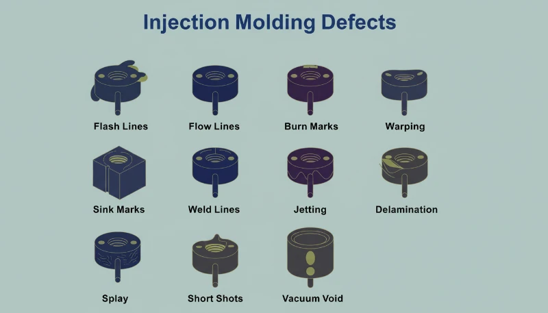
Every overmold defect traces back to one of four root causes: substrate positioning, melt flow, thermal management, or material compatibility. Here is what we see most often on the production floor and how we address each one.
| 결함 | Root Cause | Fix |
|---|---|---|
| Flash at bond line | Insufficient shut-off clearance or excessive holding pressure | Tighten shut-off to 0.05–0.10 mm; reduce hold pressure 10–20% |
| Delamination / peeling | Incompatible materials or insufficient melt temperature | Verify material compatibility testing; raise overmold temp 5–10°C |
| Thin spots / incomplete fill | Substrate not seated or trapped air | Check substrate positioning; add vents near thin areas |
| Substrate distortion | Overmold temperature too high or long cycle time | Reduce overmold temp; shorten cycle or add cooling |
| Visible ejector marks | Pins passing through overmold grip surface | 사출 대 오버몰딩 다이어그램으로 재료 접합 표시 |
| Weld line on bond surface | Gate placement causing flow fronts to meet at critical interface | Relocate gate; modify flow geometry |
The defects above account for roughly 85% of overmold scrap in our experience. The remaining 15% are edge cases—static discharge affecting material flow, batch-to-batch material variation, and mold wear affecting seal quality over long production runs. The important pattern is that most defects are preventable with proper mold design upfront and disciplined process control during production. When the mold is designed correctly and the material pair is validated through testing, the process window is wide enough that standard operators can maintain quality without constant engineering intervention.
When Should You Choose Overmolding?
Overmolding is not the answer for every multi-material product. For short runs or parts with rapidly changing graphics, the tooling premium and material minimum order quantities may not make economic sense. Here is a decision framework based on what we recommend to clients at ZetarMold.
Choose Overmolding When:
Annual production volume exceeds 50,000 units. The fixed cost of overmold tooling amortizes quickly at scale, and the elimination of secondary operations like pad printing or adhesive coating becomes economically significant. The part requires permanent, durable surface properties—soft-touch grip, abrasion resistance, or chemical resistance—that cannot be achieved with coatings or films that may degrade over time. Brand differentiation and visual quality are competitive requirements, and you want integrated graphics, logos, or color blocking that cannot peel, fade, or scratch off under normal use. The product geometry allows for clean substrate seating in the overmold cavity—deep undercuts, extreme draft angles, or complex 3D contours that prevent reliable positioning are warning signs.
Stick With Secondary Decoration When:
Volume is below 20,000 units per year. Graphics or surface treatments change frequently across small batches—promotional runs, regional variants, limited editions, or seasonal packaging. The part geometry is too complex for reliable substrate seating—extreme undercuts, living hinges, or draw ratios exceeding 2:1 make overmolding impractical. Material compatibility is questionable and the qualification timeline would exceed project schedules. In those cases, pad printing, screen printing, or adhesive films may deliver acceptable results at lower upfront cost and risk.
중간 지점도 있습니다: 전용 2색 성형기에서의 투 샷 성형은 형상이 동시 성형을 허용하는 대량 생산 제품의 경우 더 짧은 사이클 타임으로 오버몰드와 유사한 결과를 제공할 수 있습니다. 핵심은 더 진보된 기술처럼 들린다는 이유로 오버몰딩을 기본값으로 설정하기보다는 부품의 형상, 생산량, 내구성 요구사항에 맞는 표면 장식 기술을 선택하는 것입니다. 우리는 고객의 생산량이 이를 정당화하지 못하거나 형상이 기판의 안정적인 고정을 불가능하게 할 때 오버몰딩을 권하지 않았습니다—생산 현장에서 작동하지 않는 기술을 과대 판매하는 것보다 정직한 조언이 더 오래가는 관계를 구축합니다.
자주 묻는 질문
What does overmold mean?
오버몰드는 경질 플라스틱 기판 위에 일반적으로 TPE 또는 TPU와 같은 연질 플라스틱 재료를 주입하여 영구적으로 결합된 다중 재료 부품을 만드는 이차 사출 성형 공정을 의미합니다. 이 용어는 특히 동일한 사이클에서 두 재료를 동시에 주입할 수 있는 투컬러 성형과 구별되는 순차적 투샷 공정을 설명합니다. 오버몰드 부품은 파워 툴, 칫솔, 전자 제품 케이스와 같은 소비재에서 흔히 볼 수 있으며, 그립감, 편안함 또는 내구성이 제품 구매 결정과 브랜드 충성도에 직접 영향을 미치는 중요한 사용자 경험 요소인 경우에 사용됩니다.
What is the difference between mold and overmold?
몰드는 일반적으로 플라스틱 부품을 성형하는 사출 성형에 사용되는 금형 또는 다이, 즉 부품 형상을 만드는 캐비티와 코어를 의미합니다. 오버몰드는 기존 부품이나 기판 위에 두 번째 재료를 적용하는 공정을 구체적으로 설명합니다. 몰드는 도구인 반면, 오버몰드는 다중 재료 부품을 만드는 기술입니다. 오버몰드 프로젝트는 여러 개의 금형 또는 캐비티가 필요합니다. 첫 번째 사출 기판용 하나와 두 번째 사출용 하나 이상이 필요하며, 표준 성형 프로젝트는 단일 금형 캐비티만 필요할 수 있습니다. 이러한 차이를 이해하면 차기 제품의 오버몰드 제조를 조달할 때 금형 요구 사항을 정확히 명시하는 데 도움이 됩니다.
What is the difference between substrate and overmold?
기재는 오버몰드 부품에서 구조적 지지를 제공하는 경질 베이스 재료로, 일반적으로 코어 구성 요소를 형성하는 ABS, PC 또는 PP와 같은 엔지니어링 플라스틱입니다. 오버몰드는 2차 사출에서 기재 위에 적용되는 연질 재료로, 일반적으로 그립, 완충 또는 표면 보호를 제공하는 TPE 또는 TPU입니다. 기재는 구조적 하중을 지지하고 부품 형상을 정의하는 반면, 오버몰드는 기능적 표면 특성을 제공합니다. 두 재료는 오버몰딩 공정 중 화학적으로 결합하여, 파괴 없이는 오버몰드를 기재에서 분리할 수 없는 단일 통합 부품을 생성합니다.
What does it mean to mold over something?
무언가를 오버몰딩한다는 것은 기존 부품이나 기판 위 또는 주변에 녹은 플라스틱 재료를 주입하는 오버몰딩 공정을 의미합니다. 기판을 금형 캐비티에 배치한 후 오버몰드 재료를 주입하여 기판 형상 주위를 흐르고 적응시킵니다. 주입 과정에서 오버몰드 재료의 열이 기판 표면을 활성화하여 화학적 결합을 생성합니다. 그 결과 두 재료가 성형 후 조립되거나 접착되는 것이 아니라 영구적으로 통합된 단일 부품이 됩니다. 이 때문에 오버몰딩은 접착제 기반 조립 방식에서 발생하는 박리 위험을 제거합니다.
How much does overmold tooling cost compared to standard molds?
오버몰드 금형은 일반적으로 동일한 크기와 캐비티 수를 가진 표준 금형보다 25~40% 더 비쌉니다. 이 프리미엄은 기판 위치 지정 기능, 씰링을 위한 셧-오프 표면, 캐비티 형상에 대한 더 엄격한 공차, 그리고 종종 오버몰드 표면에 흠집을 남기지 않기 위한 더 복잡한 이젝션 시스템에서 비롯됩니다. 소비재 하우징용 일반적인 4캐비티 오버몰드 금형의 경우, 이는 비교 가능한 단일 재료 금형 대비 8,000~15,000달러의 추가 비용을 의미할 수 있습니다. 그러나 패드 프린팅이나 접착제 코팅과 같은 이차 장식 공정을 제거함으로써 생산된 처음 10만~20만 개 단위 내에 이 프리미엄 비용을 회수하는 경우가 많습니다.
What cycle time penalty does overmolding add?
오버몰딩은 일반적으로 동등한 부품에 대한 표준 사출 성형 대비 사이클 시간을 15~25% 증가시킵니다. 추가 시간은 기판 전송 단계(수동이든 로봇이든)와 오버몰드 재료가 기판 측에서 단열재 역할을 하기 때문에 필요한 약간 더 긴 냉각 시간에서 비롯됩니다. 20초 표준 사이클을 가진 부품의 경우, 오버몰딩 시 23~25초를 예상할 수 있습니다. 이 손실은 전송 시간이 전체 사이클 시간에서 차지하는 비중이 더 작은 대형 부품에서는 감소하며, 이차 장식 단계를 완전히 제거함으로써 종종 정당화됩니다.
Can overmolded parts be recycled?
오버몰드 부품은 분자 수준에서 결합된 두 가지 이상의 서로 다른 플라스틱을 포함하기 때문에 재활용이 어렵습니다. PP, ABS, TPE, TPU와 같은 개별 재료들은 각각 자체 재활용 흐름에서 재활용이 가능하지만, 결합된 부품은 품질을 저하시키는 기계적 또는 화학적 처리 없이는 구성 재료로 쉽게 분리될 수 없습니다. 수명 종료를 고려한 대량 생산의 경우, 재활용 가능성을 극대화하기 위해 PP 기판에 PP 기반 TPE 오버몰드와 같은 호환 가능한 재료 계열을 우선적으로 선택해야 합니다. 환경 영향은 금형이 완성된 후보다 제품 설계 단계에서 평가하는 것이 가장 좋습니다.
-
secondary injection: secondary injection refers to the second molding cycle in overmolding where the overmold material is injected around or onto the pre-formed substrate to create the final multi-material part. ↩
-
substrate: substrate refers to the base material or core of an overmolded part, typically a rigid plastic that provides structural support, onto which the overmold material is applied. ↩
-
tie layer: tie layer refers to an adhesive layer or surface treatment applied between the substrate and overmold material to enhance chemical bonding and improve adhesion strength between dissimilar plastics. ↩



 EN
EN  ES
ES  FR
FR  DE
DE  PT
PT  AR
AR  RU
RU  JA
JA  KO
KO  IT
IT  NL
NL  TR
TR  PL
PL 