 コンテンツへスキップ

肉厚[1] is arguably the single most important design parameter in injection molding. Get it right, and your part molds cleanly, functions reliably, and costs less. Get it wrong, and you’re dealing with sink marks, warpage, voids, and cycle times that eat your margin.
Key Takeaways:
- Keep nominal wall thickness between 1.5–3.0 mm for most engineering thermoplastics.
- Maintain wall variation within ±25% of the nominal value throughout the part.
- Use 3:1 taper ratio for transitions between different wall thicknesses.
- Keep rib base thickness at 50–60% of nominal wall to avoid sink marks.
- Cooling time scales with the square of wall thickness — thin-wall design has high ROI.
This guide covers everything engineers need to know about 射出成形 wall thickness: how to choose the right value, what happens when walls aren’t uniform, material-specific guidelines, and the most common mistakes from thousands of DFM reviews.
What Is Wall Thickness in Injection Molding?
Wall thickness is the distance between the outer and inner surface of a molded part at any cross-section. It determines how plastic flows through the injection mold cavity, how quickly the part cools, and whether final dimensions hold to specification.
“Wall thickness variation should stay within ±25% of the nominal value.”真
The industry guideline is ±25% variation. Exceeding this without gradual transitions causes differential shrinkage, warpage, and dimensional instability.
“A rib with base thickness equal to 80% of the nominal wall will not cause sink marks.”偽
Ribs thicker than 50–60% of nominal wall almost always produce visible sink marks because the rib creates a localized hot spot that cools much slower than the surrounding wall.
Thinner walls save material and reduce cycle time, but increase injection pressure requirements and risk short shots. Thicker walls flow more easily but cool slowly, extending cycle time and increasing the risk of voids and sink marks. The sweet spot for most engineering thermoplastics is 1.5–3.0 mm. Always verify your chosen thickness against the material supplier’s data sheet and flow simulation results before finalizing the design.
Why Is Uniform Wall Thickness So Important?
Non-uniform wall thickness is the root cause of more molding defects than any other single design error. When walls vary significantly, thick sections cool and shrink at a different rate than thin sections. This differential shrinkage射出成形[2] creates internal stresses that manifest as warpage, sink marks, and dimensional instability.
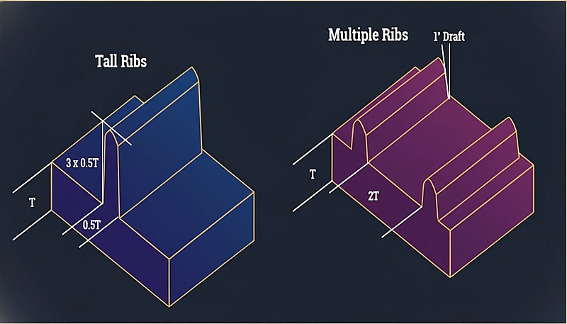
“Multiple thin ribs are generally better than one tall, thick rib for stiffness.”真
Multiple thin ribs distribute stress evenly, cool faster, and produce minimal sink marks compared to a single thick rib creating a localized thermal mass.
“A sharp 90° transition from 3 mm to 1.5 mm wall is acceptable if the thinner section is short.”偽
Abrupt transitions create stress concentrations regardless of length. They cause flow hesitation, increased residual stress, and visible surface defects. Always use the 3:1 taper ratio.
The guideline is straightforward: maintain wall thickness within ±25% of the nominal value throughout the entire part. If your nominal wall is 2.5 mm, every section should fall between 1.9 mm and 3.1 mm.
What Is the Recommended Wall Thickness by Material?
Different materials have different flow characteristics and shrinkage rates. Here’s a practical reference table based on extensive production data.
| 素材 | Min Wall (mm) | Ideal Range (mm) | Max Practical (mm) |
|---|---|---|---|
| ABS | 0.8 | 1.5–3.0 | 4.5 |
| PC(ポリカーボネート) | 0.8 | 1.5–3.0 | 4.5 |
| PP(ポリプロピレン) | 0.6 | 1.2–2.5 | 5.0 |
| PA (Nylon 6/66) | 0.6 | 1.0–3.0 | 4.0 |
| POM (Acetal) | 0.8 | 1.0–3.0 | 4.0 |
| PMMA (Acrylic) | 0.8 | 1.5–3.5 | 5.0 |
| PBT | 0.8 | 1.0–3.0 | 4.0 |
| PE(ポリエチレン) | 0.6 | 1.0–2.5 | 5.0 |
| PS(ポリスチレン) | 0.8 | 1.0–3.0 | 4.5 |
| TPE/TPU | 0.5 | 1.0–3.0 | 5.0 |
The minimum wall values represent what’s technically possible with optimized processing, not what’s recommended for production. For reliable manufacturing, stay within the ideal range.
How Do You Transition Between Different Wall Thicknesses?
Sometimes wall thickness variation is unavoidable. When it happens, the transition between thick and thin sections is critical. The standard guideline is a 3:1 taper ratio: for every 1 mm of thickness change, provide at least 3 mm of gradual transition.
Abrupt thickness changes cause flow hesitation, stress concentrations, and visible sink marks on the opposite surface. In severe cases, parts crack at thickness transitions during assembly because residual stress exceeds the material’s yield strength.
What Happens When Walls Are Too Thick?
Thick walls create three problems: excessive cycle time, internal voids, and sink marks.
Cycle Time Penalty
Cooling time scales approximately with the square of wall thickness. A part with 2 mm walls might cool in 15 seconds; the same geometry with 4 mm walls could take 50–60 seconds. Across a production run of 100,000 parts, that’s thousands of additional machine hours.
“Cooling time scales with the square of wall thickness — doubling wall quadruples cooling time.”真
This non-linear relationship is why thin-wall design has such high ROI. Reducing wall from 4mm to 2mm can cut cooling time by 75%.
“Reducing wall thickness always improves part quality and production efficiency.”偽
While thin walls reduce material usage and cycle time, walls that are too thin cause short shots, increase injection pressure requirements, and compromise structural integrity. The optimal thickness balances flow, strength, and cost.
Internal Voids
When thick sections cool, the outer skin solidifies first while the interior is still molten. As the interior shrinks, it pulls away from the solidified skin, creating internal voids that reduce structural integrity — particularly problematic in load-bearing applications.
シンクマーク
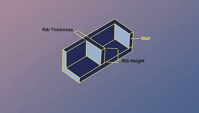
Sink marks are the surface manifestation of the same phenomenon. When material at a thick section shrinks, it pulls the surface inward, creating a visible depression especially noticeable on glossy surfaces. Rib-to-wall ratios directly control sink severity: ribs thicker than 50–60% of nominal wall almost always produce visible sink marks.
What Happens When Walls Are Too Thin?
Thin walls carry their own risks. The most immediate is short shots — the plastic melt freezes before completely filling the cavity. This is especially problematic with high-viscosity materials like polycarbonate and long flow paths, where the melt viscosity is already high.
Thin walls also increase injection pressure requirements. If required pressure exceeds machine capability, you get incomplete fills and high residual stress.
構造的完全性も懸念事項です — 落下試験が行われる民生品の薄肉部品には、常に安全マージンを含めてください。静的荷重には耐える部品でも、肉厚が薄すぎると衝撃で破損する可能性があります。
リブとボスは肉厚にどのように影響しますか?
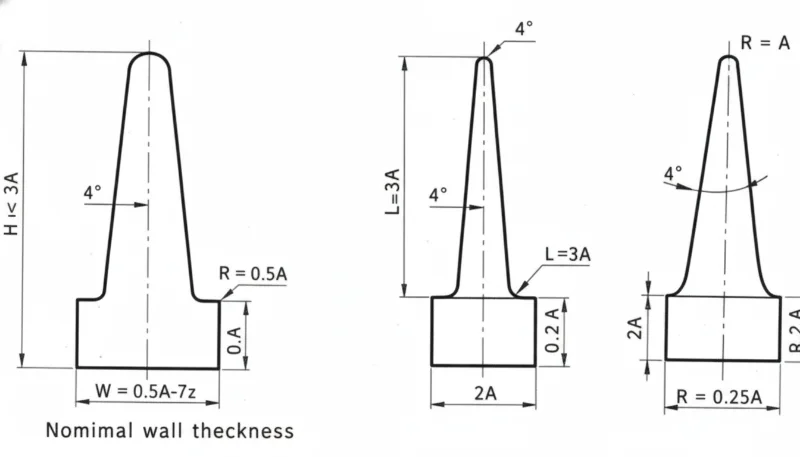
リブとボスは肉厚と関係する最も一般的な形状です。リブの場合:基部の厚さは基本肉厚の50~60%、高さは基本肉厚の3倍を超えず、複数の細いリブが1本の高く厚いリブよりも優れています。
ボスの場合、コア抜きが解決策です — コアピンで中心をくり抜き、均一な肉厚を維持します。ボスの外径は穴径の2~3倍以内に収めるべきです。これらの比例関係を守った部品は射出成形に適しています。 射出成形金型[3] きれいに成形されます;それから外れると、継続的な品質問題を生み出します。
肉厚はサイクル時間にどのように影響しますか?
で 射出成形, 冷却時間[4] 通常は総サイクル時間の50~70%を占め、最も厚い断面によって決定されます。
| 基本肉厚 | 典型的な冷却時間 | 相対サイクルコスト |
|---|---|---|
| 1.5 mm | 8–12 秒 | 1.0× (baseline) |
| 2.0 mm | 12–18 秒 | 1.3× |
| 2.5 mm | 18~25秒 | 1.6× |
| 3.0 mm | 25–35 秒 | 2.0× |
| 4.0 mm | 40–60 秒 | 3.0× |
肉厚を2.0 mmから3.0 mmにすると、サイクルタイムだけでも部品あたりの製造コストが約2倍になります。構造的に可能な場合の薄肉設計は、射出成形における最も投資対効果の高い最適化の一つです。
最も一般的な肉厚の間違いは何ですか?
- 均一肉厚を無視。 肉厚解析なしで設計された部品は、公称肉厚の半分の箇所と、公称肉厚の3倍の箇所が混在し、シンクマーク、反り、サイクルタイムの延長を引き起こします。
- 強度のための過剰な肉厚増加。 リブの方が軽量で生産が速く、寸法安定性に優れる場合、エンジニアは材料を追加する。
- リブのプロポーションを無視。 基本肉厚の80~100%のリブは深いシンクマークを引き起こします。50~60%のルールは全ての材料に適用されます。
- 急激な肉厚変化。 テーパーのない急激な肉厚変化は、応力集中部と外観不良を生み出します。
- フローシミュレーションを実行しない。 最新のツールは充填パターン、圧力、冷却を高精度で予測します。複雑な部品でシミュレーションを省略すると、通常は損失が生じます。
デザイン提出前に確認すべき事項は何ですか?
設計を金型製作に提出する前に、このチェックリストを確認してください。各項目の確認には数秒しかかからず、高額な金型修正を防ぐことができます。
| Check Item | 合格基準 |
|---|---|
| 材料の理想範囲内の公称肉厚 | ✓ |
| 肉厚変動は公称値の ±25% 以内 | ✓ または注記 |
| すべてのリブは基本肉厚の60%以下 | ✓ |
| 肉厚遷移は 3:1 のテーパーを使用 | ✓ |
| ボス外径 ≤3× 穴径 | ✓ |
| 最厚部を特定し確認済み | ✓ |
| 流動シミュレーション完了 | ✓ |
金型が製作される前に肉厚を最適化することが不可欠です — 肉厚の問題を修正する最も安価な場所は、CAD上であって、鋼材の中ではありません。
肉厚に関するよくある質問
射出成形における最小肉厚は何ですか?
ほとんどのエンジニアリング熱可塑性樹脂(ABS、PC、ナイロン)では、短い流動経路の場合、実用的な最小肉厚は 0.8 mm です。PP や PE などの高流動材料では、0.5 mm まで薄くできます。これらの最小値は高い射出圧力を必要とし、ショートショットのリスクを伴います。
部品全体で肉厚は変化しますか?
はい、ただし変動は公称壁厚の±25%以内に収め、異なる厚さ間の遷移は3:1のテーパー比を用いて段階的に行う必要があります。
壁厚は収縮とどのように関連していますか?
厚い部分はより多くの材料が冷却収縮するため、より大きく収縮します。この不均一な収縮が射出成形部品の反りの主な原因となります。
壁厚は部品の強度に影響しますか?
はい、しかし線形ではありません。肉厚を2倍にすると曲げ剛性は2倍以上になります(肉厚の3乗に比例します)。ただし、肉厚を増すと残留応力やボイドリスクも増加します。適切に設計されたリブは、しばしばより優れた強度対重量比を実現します。
肉厚はどのように測定しますか?
CADソフトウェア(SolidWorks、Creo、およびほとんどのMCADパッケージに組み込まれています)の肉厚分析ツールを使用します。物理部品では、超音波肉厚計による非破壊測定、または切断した断面をノギスで直接測定します。生産中は、超音波測定が継続的な品質監視の標準方法です。
薄肉成形とは何ですか?
薄肉成形とは、肉厚が1.0 mm未満(電子機器筐体では0.3 mm程度まで)の部品を指します。非常に高い圧力(200 MPa以上)に対応できる高速成形機と専用の金型設計が必要です。
Bottom line: 肉厚は1.5~3.0 mmに保ち、±25%の均一性を維持し、3:1のテーパ遷移を使用し、リブは基準肉厚の50~60%にします。これら4つの規則により、肉厚関連の欠陥の90%を防止できます。
設計初期段階での肉厚決定は、部品が効率的に成形されるか、生産全体で問題が発生するかを左右します。400以上の材料で数千の肉厚設計を最適化したエンジニアによるDFMレビューをご希望の場合、 ZetarMoldのチームにご連絡ください上海拠点では45台の射出成形機(90T~1850T)を稼働し、30名以上の英語対応プロジェクトマネージャーがサポートを提供します。


